2011 INFINITI QX56 length
[x] Cancel search: lengthPage 4285 of 5598
SB-10
< REMOVAL AND INSTALLATION >
SECOND SEAT BELT
SECOND SEAT BELT
SEAT BELT RETRACTOR
SEAT BELT RETRACTOR : InspectionINFOID:0000000006217621
AFTER A COLLISION
WARNING:
Inspect all seat belt assemblies including retractors and attached hardware after any collision.
NISSAN/INFINITI recommends that all seat belt assemblies in use during a collision be replaced
unless the collision was minor and th e belts show no damage and continue to operate properly. Fail-
ure to do so could result in seri ous personal injury in an accident. Seat belt assemblies not in use dur-
ing a collision should also be re placed if either damage or improper operation was noted. Seat belt
pre-tensioners should be replaced even if the seat be lts were not in use during a frontal collision in
which the air bags were deployed.
Replace any seat belt assembly (including anchor bolts) if:
The seat belt is in use at the time of a collision (e xcept for minor collisions and the belts, retractors and buck-
les show no damage and continue to operate properly).
The seat belt is damaged in an accident (i.e. to rn webbing, bent retractor or guide, etc.).
The seat belt attaching point is damaged in an accident . Inspect the seat belt attaching area for damage or
distortion and repair if necessary before installing a new seat belt assembly.
Anchor bolts are deformed or worn out.
The seat belt pre-tensioners must be replaced even if t he seat belts were not in use during the collision in
which the air bags were deployed.
PRELIMINARY CHECKS
1. Check that the seat belt retractor, s eat belt anchor and buckle bolts are tightened firmly.
2. Check retractor operation:
a. Fully extend the seat belt webbing and c heck for twists, tears or other damage.
b. Allow the seat belt to retract. Check that webbing retu rns smoothly and completely into the retractor. If the
seat belt does not return smoothly, wipe the inside of the loops with a clean paper cloth. Dirt build-up in the
loops of that upper anchors can cause the seat belts to retract slowly.
c. Fasten the seat belt. Check that seat belt returns sm oothly and completely to the retractor. If the webbing
does not return smoothly, the cause may be an accumulation of dust or dirt. Use the “SEAT BELT TAPE
SET” and perform the following steps.
3. Repeat steps above if necessary to check the other seat belts.
SEAT BELT RETRACTOR ON-VEHICLE CHECK
Emergency Locking Retractors (ELR) and Automatic Locking Retractors (ALR)
NOTE:
All seat belt retractors are Emergency Locking Retr actors (ELR) type. In an emergency (sudden stop) the
retractor will lock and prevent the webbing from extendi ng any further. All 3-point type seat belt retractors
except the driver seat belt also have an Automati c Locking Retractors (ALR) mode. The ALR mode (also
called child restraint mode) is used when installing child seats. The ALR mode is activated when the seat belt
is fully extended. When the webbing is then retracted part ially, the ALR mode automatically locks the seat belt
in a specific position so the webbing cannot be extended any further. To cancel the ALR mode, allow the seat
belt to fully wind back into the retractor.
Check the seat belt retractors with the following test(s ) to determine if a retractor assembly is operating prop-
erly.
ELR Function Stationary Check
Grasp the shoulder webbing and pull forward quickly. T he retractor should lock and prevent the belt from
extending further.
ALR Function Stationary Check
1. Pull out the entire length of seat belt from retractor until a click is heard.
2. Retract the webbing partially. A clicking noise should be heard as the webbing retracts indicating that the retractor is in the Automatic Locking Retractors (ALR) mode.
Revision: 2010 May2011 QX56
Page 4286 of 5598
SECOND SEAT BELTSB-11
< REMOVAL AND INSTALLATION >
C
DE
F
G
I
J
K L
M A
B
SB
N
O P
3. Grasp the seat belt and try to pull out the retractor. The webbing must lock and not extend any further. If it
does not operate normally, replace the retractor assembly.
4. Allow the entire length of the webbing to retract to cancel the automatic locking mode.
ELR Function Moving Check
WARNING:
Perform the following test in a safe, open area clear of other vehicles and obstructions (for example, a
large, empty parking lot). Road surface must be p aved and dry. Never perform the following test on
wet or gravel roads or on public streets and highways. This could result in an accident and serious
personal injury. The driver and passenger must be prepared to brace themselves in the event that the
retractor does not lock.
1. Fasten driver seat belt. Buckle a passenger into the seat for the belt that is to be tested.
2. Proceed to the designated safe area.
3. Drive the vehicle at approximately 16 km/h ( 10 MPH). Notify any passengers of a pending sudden stop
and the driver and passenger must be prepared to brac e themselves in the event that the retractor does
not lock. Apply brakes firmly and make a very hard stop.
During stopping, seat belts should lock and not be extended. If the seat belt retractor assembly does not lock,
perform the retractor off-vehicle check.
SEAT BELT RETRACTOR OFF-VEHICLE CHECK
1. Remove the second seat belt retractor. Refer to SB-13, "SEAT BELT RETRACTOR : Removal and Instal-
lation".
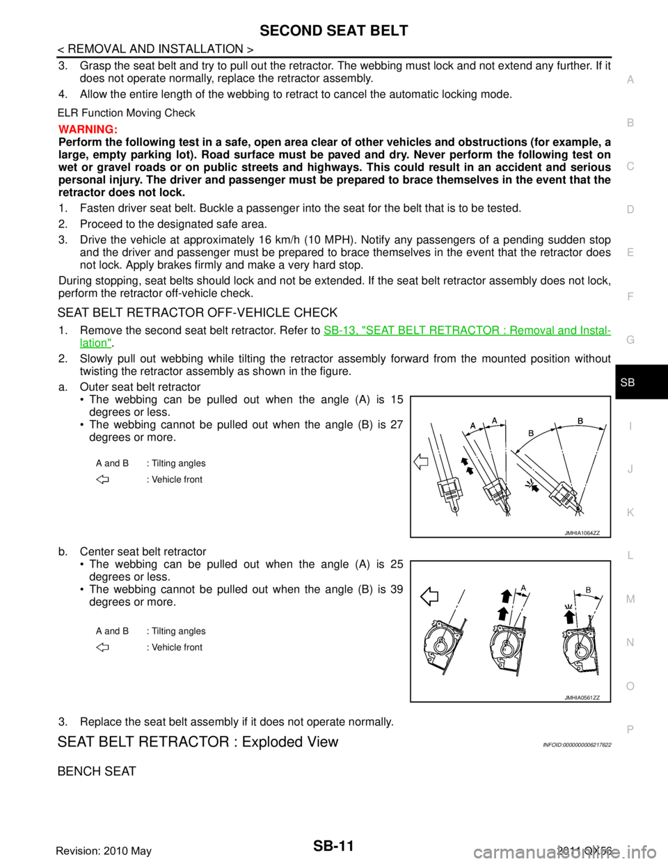
2. Slowly pull out webbing while tilting the retracto r assembly forward from the mounted position without
twisting the retractor assembly as shown in the figure.
a. Outer seat belt retractor The webbing can be pulled out when the angle (A) is 15degrees or less.
The webbing cannot be pulled out when the angle (B) is 27
degrees or more.
b. Center seat belt retractor The webbing can be pulled out when the angle (A) is 25
degrees or less.
The webbing cannot be pulled out when the angle (B) is 39
degrees or more.
3. Replace the seat belt assembly if it does not operate normally.
SEAT BELT RETRACTOR : Exploded ViewINFOID:0000000006217622
BENCH SEAT
A and B : Tilting angles : Vehicle front
JMHIA1064ZZ
A and B : Tilting angles
: Vehicle front
JMHIA0561ZZ
Revision: 2010 May2011 QX56
Page 4292 of 5598
THIRD SEAT BELTSB-17
< REMOVAL AND INSTALLATION >
C
DE
F
G
I
J
K L
M A
B
SB
N
O P
THIRD SEAT BELT
SEAT BELT RETRACTOR
SEAT BELT RETRACTOR : InspectionINFOID:0000000006217627
AFTER A COLLISION
WARNING:
Inspect all seat belt assemblies in cluding retractors and attached hardware after any collision.
NISSAN/INFINITI recommends that all seat belt assemblies in use during a collision be replaced
unless the collision was minor and th e belts show no damage and continue to operate properly. Fail-
ure to do so could result in serious personal inju ry in an accident. Seat belt assemblies not in use dur-
ing a collision should also be replaced if either da mage or improper operation was noted. Seat belt
pre-tensioners should be replaced even if the seat be lts were not in use during a frontal collision in
which the air bags were deployed.
Replace any seat belt assembly (including anchor bolts) if:
The seat belt is in use at the time of a collision (exc ept for minor collisions and the belts, retractors and buck-
les show no damage and continue to operate properly).
The seat belt is damaged in an accident (i.e. to rn webbing, bent retractor or guide, etc.).
The seat belt attaching point is damaged in an accident . Inspect the seat belt attaching area for damage or
distortion and repair if necessary before installing a new seat belt assembly.
Anchor bolts are deformed or worn out.
The seat belt pre-tensioners must be replaced even if t he seat belts were not in use during the collision in
which the air bags were deployed.
PRELIMINARY CHECKS
1. Check that the seat belt retractor, seat belt anchor and buckle bolts are tightened firmly.
2. Check retractor operation:
a. Fully extend the seat belt webbing and check for twists, tears or other damage.
b. Allow the seat belt to retract. Check that webbing retu rns smoothly and completely into the retractor. If the
seat belt does not return smoothly, wipe the inside of t he loops with a clean paper cloth. Dirt build-up in the
loops of that upper anchors can cause the seat belts to retract slowly.
c. Fasten the seat belt. Check that seat belt returns sm oothly and completely to the retractor. If the webbing
does not return smoothly, the cause may be an accu mulation of dust or dirt. Use the “SEAT BELT TAPE
SET” and perform the following steps.
3. Repeat steps above if necessary to check the other seat belts.
SEAT BELT RETRACTOR ON-VEHICLE CHECK
Emergency Locking Retractors (ELR) and Automatic Locking Retractors (ALR)
NOTE:
All seat belt retractors are Emergency Locking Retr actors (ELR) type. In an emergency (sudden stop) the
retractor will lock and prevent the webbing from extendi ng any further. All 3-point type seat belt retractors
except the driver seat belt also have an Automati c Locking Retractors (ALR) mode. The ALR mode (also
called child restraint mode) is used when installing child seats. The ALR mode is activated when the seat belt
is fully extended. When the webbing is then retracted part ially, the ALR mode automatically locks the seat belt
in a specific position so the webbi ng cannot be extended any further. To c ancel the ALR mode, allow the seat
belt to fully wind back into the retractor.
Check the seat belt retractors with the following test(s ) to determine if a retractor assembly is operating prop-
erly.
ELR Function Stationary Check
Grasp the shoulder webbing and pull forward quickly. The retractor should lock and prevent the belt from
extending further.
ALR Function Stationary Check
1. Pull out the entire length of seat bel t from retractor until a click is heard.
2. Retract the webbing partially. A clicking noise should be heard as the webbing retracts indicating that the
retractor is in the Automatic Locking Retractors (ALR) mode.
Revision: 2010 May2011 QX56
Page 4293 of 5598
SB-18
< REMOVAL AND INSTALLATION >
THIRD SEAT BELT
3. Grasp the seat belt and try to pull out the retractor. The webbing must lock and not extend any further. If it
does not operate normally, replace the retractor assembly.
4. Allow the entire length of the webbing to re tract to cancel the automatic locking mode.
ELR Function Moving Check
WARNING:
Perform the following test in a safe, open area clear of other vehicles and obstructions (for example, a
large, empty parking lot). Road surface must be p aved and dry. Never perform the following test on
wet or gravel roads or on public streets and highw ays. This could result in an accident and serious
personal injury. The driver and passenger must be prepared to brace themselves in the event that the
retractor does not lock.
1. Fasten driver seat belt. Buckle a passenger in to the seat for the belt that is to be tested.
2. Proceed to the designated safe area.
3. Drive the vehicle at approximately 16 km/h ( 10 MPH). Notify any passengers of a pending sudden stop
and the driver and passenger must be prepared to brace themselves in the event that the retractor does
not lock. Apply brakes firmly and make a very hard stop.
During stopping, seat belts should lock and not be extended. If the seat belt retractor assembly does not lock,
perform the retractor off-vehicle check.
SEAT BELT RETRACTOR OFF-VEHICLE CHECK
1. Remove the third seat belt retractor. Refer to SB-19, "SEAT BELT RETRACTOR : Removal and Installa-
tion".
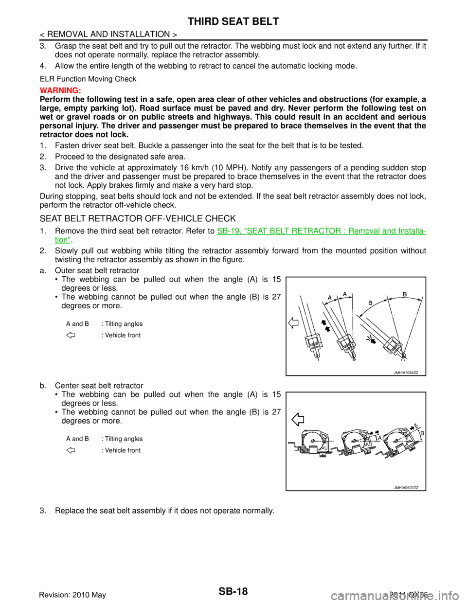
2. Slowly pull out webbing while tilting the retracto r assembly forward from the mounted position without
twisting the retractor assembly as shown in the figure.
a. Outer seat belt retractor The webbing can be pulled out when the angle (A) is 15degrees or less.
The webbing cannot be pulled out when the angle (B) is 27
degrees or more.
b. Center seat belt retractor The webbing can be pulled out when the angle (A) is 15
degrees or less.
The webbing cannot be pulled out when the angle (B) is 27
degrees or more.
3. Replace the seat belt assembly if it does not operate normally.
A and B : Tilting angles : Vehicle front
JMHIA1064ZZ
A and B : Tilting angles: Vehicle front
JMHIA0522ZZ
Revision: 2010 May2011 QX56
Page 4989 of 5598

ST-2
STEERING WHEEL ...........................................33
Exploded View ..................................................... ...33
Removal and Installation ........................................33
STEERING COLUMN ........................................34
Exploded View ..................................................... ...34
Removal and Installation ........................................34
Inspection ...............................................................35
STEERING SHAFT ............................................37
Exploded View ..................................................... ...37
Removal and Installation ........................................37
Inspection ...............................................................39
STEERING GEAR AND LINKAGE ....................41
Exploded View ..................................................... ...41
Removal and Installation ........................................42
Disassembly and Assembly ....................................43
Inspection ...............................................................46
POWER STEERING OIL PUMP ........................48
Exploded View ..................................................... ...48
Removal and Installation ........................................49
Disassembly and Assembly ....................................50
Inspection ...............................................................52
HYDRAULIC LINE .......................................... ...54
Exploded View ..................................................... ...54
HEATED STEERING WHEEL SWITCH ............56
Exploded View ..................................................... ...56
Removal and Installation .........................................56
SERVICE DATA AND SPECIFICATIONS
(SDS) .......... ................................................
57
SERVICE DATA AND SPECIFICATIONS
(SDS) .............................................................. ...
57
General Specifications ......................................... ...57
Steering Wheel Axial End Play and Play ................57
Steering Wheel Turning Force ................................57
Steering Angle ........................................................57
Steering Column Length .........................................57
Steering Column Mounting Dimensions ..................57
Steering Column Operating Range .........................57
Steering Shaft Sliding Range ..................................58
Rack Sliding Force ..................................................58
Rack Stroke ............................................................58
Socket Swing Force and Rotating Torque ..............58
Socket Axial End Play .............................................58
Inner Socket Length ................................................58
Relief Oil Pressure ..................................................58
Revision: 2010 May2011 QX56
Page 5022 of 5598
STEERING COLUMNST-35
< REMOVAL AND INSTALLATION >
C
DE
F
H I
J
K L
M A
B
ST
N
O P
If necessary, remove telescopic motor, tilt motor, and brackets.
12. Perform inspection after removal. Refer to ST-35, "
Inspection".
INSTALLATION
Note the following, and install in the reverse order of removal.
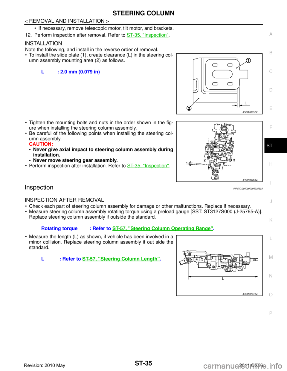
To install the slide plate (1), create clearance (L) in the steering col-
umn assembly mounting area (2) as follows.
Tighten the mounting bolts and nuts in the order shown in the fig- ure when installing the steering column assembly.
Be careful of the following points when installing the steering col- umn assembly.
CAUTION:
Never give axial impact to steering column assembly during installation.
Never move steering gear assembly.
Perform inspection after installation. Refer to ST-35, "
Inspection".
InspectionINFOID:0000000006225603
INSPECTION AFTER REMOVAL
Check each part of steering column assembly for damage or other malfunctions. Replace if necessary.
Measure steering column assembly rotating torque using a preload gauge [SST: ST3127S000 (J-25765-A)]. Replace steering column assembly if outside the standard.
Measure the length (L) as shown, if vehicle has been involved in a minor collision. Replace steering column assembly if out side the
standard. L : 2.0 mm (0.079 in)
JSGIA0315ZZ
JPGIA0026ZZ
Rotating torque : Refer to
ST-57, "Steering Column Operating Range".
L : Refer to ST-57, "
Steering Column Length".
JSGIA0797ZZ
Revision: 2010 May2011 QX56
Page 5025 of 5598
ST-38
< REMOVAL AND INSTALLATION >
STEERING SHAFT
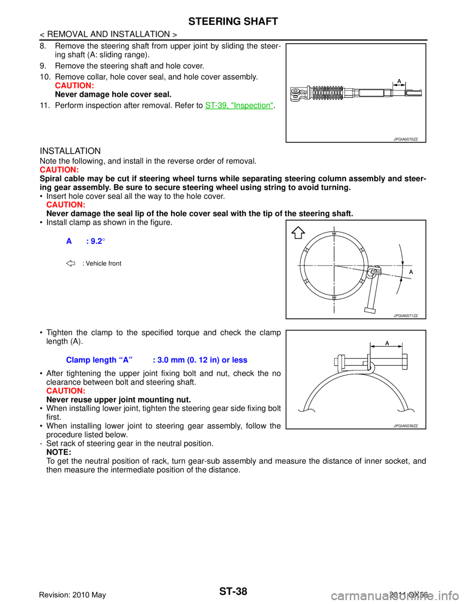
8. Remove the steering shaft from upper joint by sliding the steer-ing shaft (A: sliding range).
9. Remove the steering shaft and hole cover.
10. Remove collar, hole cover seal, and hole cover assembly. CAUTION:
Never damage hole cover seal.
11. Perform inspection after removal. Refer to ST-39, "
Inspection".
INSTALLATION
Note the following, and install in the reverse order of removal.
CAUTION:
Spiral cable may be cut if steering wheel turns while separating steering column assembly and steer-
ing gear assembly. Be sure to secure steer ing wheel using string to avoid turning.
Insert hole cover seal all the way to the hole cover. CAUTION:
Never damage the seal lip of the hole cover seal with the tip of the steering shaft.
Install clamp as shown in the figure.
Tighten the clamp to the spec ified torque and check the clamp
length (A).
After tightening the upper joint fixing bolt and nut, check the no clearance between bolt and steering shaft.
CAUTION:
Never reuse upper joint mounting nut.
When installing lower joint, tighten the steering gear side fixing bolt
first.
When installing lower joint to steering gear assembly, follow the procedure listed below.
- Set rack of steering gear in the neutral position. NOTE:
To get the neutral position of rack, turn gear-sub as sembly and measure the distance of inner socket, and
then measure the intermediate position of the distance.
JPGIA0070ZZ
A: 9.2 °
: Vehicle front
JPGIA0071ZZ
Clamp length “A” : 3.0 mm (0. 12 in) or less
JPGIA0039ZZ
Revision: 2010 May2011 QX56
Page 5026 of 5598
STEERING SHAFTST-39
< REMOVAL AND INSTALLATION >
C
DE
F
H I
J
K L
M A
B
ST
N
O P
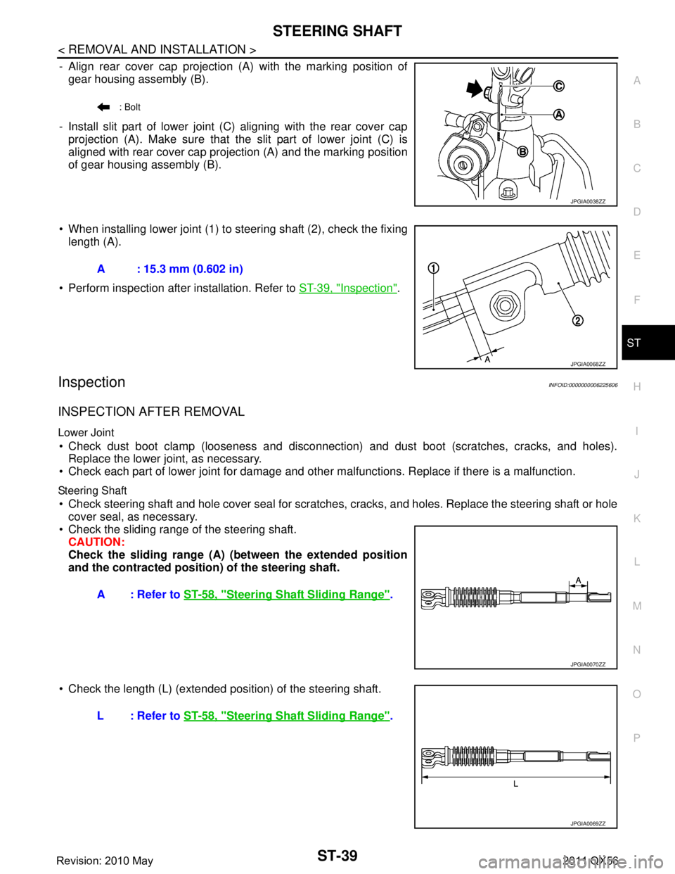
- Align rear cover cap projection (A) with the marking position of gear housing assembly (B).
- Install slit part of lower joint (C) aligning with the rear cover cap projection (A). Make sure that the slit part of lower joint (C) is
aligned with rear cover cap projection (A) and the marking position
of gear housing assembly (B).
When installing lower joint (1) to steering shaft (2), check the fixing length (A).
Perform inspection after installation. Refer to ST-39, "
Inspection".
InspectionINFOID:0000000006225606
INSPECTION AFTER REMOVAL
Lower Joint
Check dust boot clamp (looseness and disconnection) and dust boot (scratches, cracks, and holes).
Replace the lower joint, as necessary.
Check each part of lower joint for damage and other malfunctions. Replace if there is a malfunction.
Steering Shaft
Check steering shaft and hole cover seal for scratches, cracks, and holes. Replace the stee\
ring shaft or hole
cover seal, as necessary.
Check the sliding range of the steering shaft.
CAUTION:
Check the sliding range (A) (b etween the extended position
and the contracted position) of the steering shaft.
Check the length (L) (extended posit ion) of the steering shaft.
: Bolt
JPGIA0038ZZ
A : 15.3 mm (0.602 in)
JPGIA0068ZZ
A : Refer to ST-58, "Steering Shaft Sliding Range".
JPGIA0070ZZ
L : Refer to ST-58, "Steering Shaft Sliding Range".
JPGIA0069ZZ
Revision: 2010 May2011 QX56