2011 INFINITI QX56 fuse diagram
[x] Cancel search: fuse diagramPage 2333 of 5598
![INFINITI QX56 2011 Factory Service Manual
P0420, P0430 THREE WAY CATALYST FUNCTIONEC-309
< DTC/CIRCUIT DIAGNOSIS > [VK56VD]
C
D
E
F
G H
I
J
K L
M A
EC
NP
O
Diagnosis ProcedureINFOID:0000000006217853
1.CHECK EXHAUST SYSTEM
Visually check exha INFINITI QX56 2011 Factory Service Manual
P0420, P0430 THREE WAY CATALYST FUNCTIONEC-309
< DTC/CIRCUIT DIAGNOSIS > [VK56VD]
C
D
E
F
G H
I
J
K L
M A
EC
NP
O
Diagnosis ProcedureINFOID:0000000006217853
1.CHECK EXHAUST SYSTEM
Visually check exha](/manual-img/42/57033/w960_57033-2332.png)
P0420, P0430 THREE WAY CATALYST FUNCTIONEC-309
< DTC/CIRCUIT DIAGNOSIS > [VK56VD]
C
D
E
F
G H
I
J
K L
M A
EC
NP
O
Diagnosis ProcedureINFOID:0000000006217853
1.CHECK EXHAUST SYSTEM
Visually check exhaust tubes and muffler for dents.
Is the inspection result normal?
YES >> GO TO 2.
NO >> Repair or replace malfunctioning part.
2.CHECK EXHAUST GAS LEAKAGE
1. Start engine and run it at idle.
2. Listen for an exhaust gas leakage before the three way catalyst (manifold).
Is exhaust gas leakage detected?
YES >> Repair or replace malfunctioning part.
NO >> GO TO 3.
3.CHECK INTAKE AIR LEAKAGE
Listen for an intake air leakage after the mass air flow sensor.
Is intake air leakage detected?
YES >> Repair or replace malfunctioning part.
NO >> GO TO 4.
4.CHECK IDLE SPEED AND IGNITION TIMING
Check idle speed and ignition timing.
For procedure, refer to EC-530, "
Inspection" and EC-531, "Inspection".
For specification, refer to EC-538, "
Idle Speed" and EC-538, "Ignition Timing".
Is the inspection result normal?
YES >> GO TO 5.
NO >> Follow the EC-139, "
Work Procedure".
5.CHECK FUEL INJECTORS
Refer to EC-498, "
Component Function Check".
Is the inspection result normal?
YES >> GO TO 6.
NO >> Perform EC-498, "
Diagnosis Procedure".
6.CHECK FUNCTION OF IGNITION COIL-I
CAUTION:
Perform the following procedure in a place with no combustible objects and good ventilation.
1. Turn ignition switch OFF.
2. Remove fuel pump fuse in IPDM E/R to release fuel pressure.
NOTE:
For the fuse number, refer to EC-114, "
Wiring Diagram".
For the fuse arrangement, refer to PG-140, "
Fuse, Connector and Terminal Arrangement".
Do not use CONSULT-III to release fuel pressure, or fuel pressure applies again during the following
procedure.
3. Start engine.
4. After engine stalls, crank it 2 or 3 times to release all fuel pressure.
5. Turn ignition switch OFF.
PBIB1216E
Revision: 2010 May2011 QX56
Page 2534 of 5598
![INFINITI QX56 2011 Factory Service Manual
EC-510
< DTC/CIRCUIT DIAGNOSIS >[VK56VD]
IGNITION SIGNAL
3. Remove fuel pump fuse in IPDM E/R to release fuel pressure.
NOTE:
For the fuse number, refer to EC-114, "
Wiring Diagram".
For the fus INFINITI QX56 2011 Factory Service Manual
EC-510
< DTC/CIRCUIT DIAGNOSIS >[VK56VD]
IGNITION SIGNAL
3. Remove fuel pump fuse in IPDM E/R to release fuel pressure.
NOTE:
For the fuse number, refer to EC-114, "
Wiring Diagram".
For the fus](/manual-img/42/57033/w960_57033-2533.png)
EC-510
< DTC/CIRCUIT DIAGNOSIS >[VK56VD]
IGNITION SIGNAL
3. Remove fuel pump fuse in IPDM E/R to release fuel pressure.
NOTE:
For the fuse number, refer to EC-114, "
Wiring Diagram".
For the fuse arrangement, refer to PG-143, "
Fuse, Connector and Terminal Arrangement".
Do not use CONSULT-III to release fuel pressure , or fuel pressure applies again during the following
procedure.
4. Start engine.
5. After engine stalls, crank it 2 or 3 times to release all fuel pressure.
6. Turn ignition switch OFF.
7. Remove all ignition coil harness connectors to avoi d the electrical discharge from the ignition coils.
8. Remove ignition coil and spark plug of the cylinder to be checked.
9. Crank engine for 5 seconds or more to remove combustion gas in the cylinder.
10. Connect spark plug and harness connector to ignition coil.
11. Fix ignition coil using a rope etc. with gap of 13 - 17 mm (0.52 - 0.66 in) between the edge of the spark plug and grounded metal
portion as shown in the figure.
12. Crank engine for approximately 3 seconds, and check whether
spark is generated between the spark plug and the grounded
metal portion.
CAUTION:
Never place the spark plug and the ignition coil within 50
cm (19.7 in) each other. Be careful not to get an electrical
shock while checking, becau se the electrical discharge
voltage becomes 20 kV or more.
It might damage the ignition coil if the gap of more than 17 mm (0.66 in) is made.
NOTE:
When the gap is less than 13 mm (0.52 in), a spark might be generated even if the coil is malfunc-
tioning.
Is the inspection result normal?
YES >> INSPECTION END
NO >> Replace malfunctioning ignition coil with power transistor.
Component Inspection (Condenser)INFOID:0000000006218014
1.CHECK CONDENSER
1. Turn ignition switch OFF.
2. Disconnect condenser harness connector.
3. Check resistance between condenser terminals as per the following.
Is the inspection result normal?
YES >> INSPECTION END
NO >> Replace condenser. Spark should be generated.
JMBIA0066GB
Terminals Resistance
1 and 2 Above 1 M Ω [at 25 °C (77 °F)]
Revision: 2010 May2011 QX56
Page 2578 of 5598
EM-16
< BASIC INSPECTION >
COMPRESSION PRESSURE
COMPRESSION PRESSURE
InspectionINFOID:0000000006289521
1. Warm up engine thoroughly. Then, stop it.
2. Release fuel pressure. Refer to EC-153, "
Work Procedure".
CAUTION:
If CONSULT-III is not used to release fuel pr essure leave the fuel pump fuse disconnected until
step 7.
3. Remove fuel pump fuse in IPDM E/R. NOTE:
For the fuse number, refer to EC-114, "
Wiring Diagram".
For the fuse arrangement, refer to PG-143, "
Fuse, Connector and Terminal Arrangement".
4. Remove engine cover. Refer to EM-25, "
Exploded View".
5. Remove ignition coil and spark plug from each cylinder. Refer to EM-29, "
Exploded View".
6. Connect engine tachometer (not required in use of CONSULT-III).
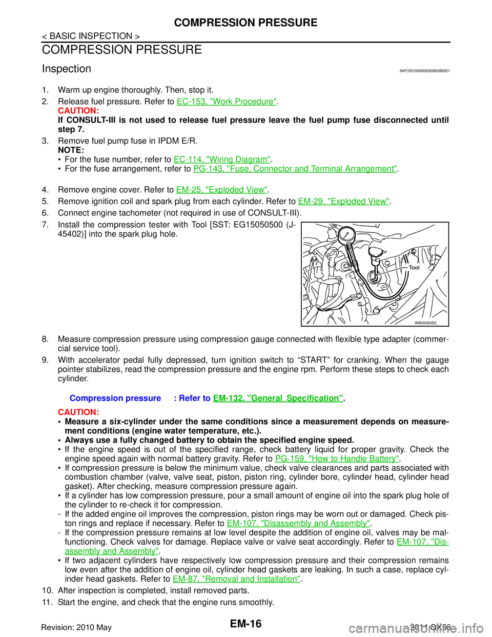
7. Install the compression tester with Tool [SST: EG15050500 (J- 45402)] into the spark plug hole.
8. Measure compression pressure using compressi on gauge connected with flexible type adapter (commer-
cial service tool).
9. With accelerator pedal fully depressed, turn ignition switch to “START” for cranking. When the gauge pointer stabilizes, read the compression pressure and the engine rpm. Perform these steps to check each
cylinder.
CAUTION:
Measure a six-cylinder under the same conditio ns since a measurement depends on measure-
ment conditions (engine water temperature, etc.).
Always use a fully changed battery to obtain the specified engine speed.
If the engine speed is out of the specified range, c heck battery liquid for proper gravity. Check the
engine speed again with normal battery gravity. Refer to PG-159, "
How to Handle Battery".
If compression pressure is below the minimum value, check valve clearances and parts associated with combustion chamber (valve, valve seat, piston, pi ston ring, cylinder bore, cylinder head, cylinder head
gasket). After checking, measure compression pressure again.
If a cylinder has low compression pressure, pour a small amount of engine oil into the spark plug hole of the cylinder to re-check it for compression.
- If the added engine oil improves the compression, pi ston rings may be worn out or damaged. Check pis-
ton rings and replace if necessary. Refer to EM-107, "
Disassembly and Assembly".
- If the compression pressure remains at low level despite the addition of engine oil, valves may be mal- functioning. Check valves for damage. Replace valve or valve seat accordingly. Refer to EM-107, "
Dis-
assembly and Assembly".
If two adjacent cylinders have respectively low co mpression pressure and their compression remains
low even after the addition of engine oil, cylinder head gaskets are leaking. In such a case, replace cyl-
inder head gaskets. Refer to EM-87, "
Removal and Installation".
10. After inspection is completed, install removed parts.
11. Start the engine, and check that the engine runs smoothly.
WBIA0605E
Compression pressure : Refer to EM-132, "GeneralSpecification".
Revision: 2010 May2011 QX56
Page 2974 of 5598
GI-10
< HOW TO USE THIS MANUAL >
HOW TO READ WIRING DIAGRAMS
Sample/Wiring Diagram -Example-
INFOID:0000000006282194
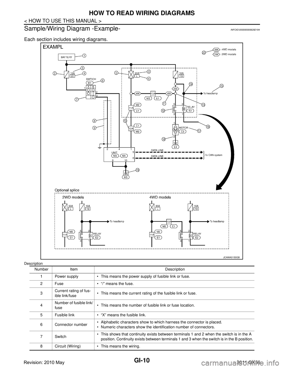
Each section includes wiring diagrams.
Description
JCAWA0150GB
Number Item Description 1 Power supply This means the power supply of fusible link or fuse.
2 Fuse “/” means the fuse.
3 Current rating of fus-
ible link/fuse This means the current rating of the fusible link or fuse.
4 Number of fusible link/
fuse
This means the number of fusible link or fuse location.
5 Fusible link “X” means the fusible link.
6 Connector number Alphabetic characters show to which harness the connector is placed.
Numeric characters show the identification number of connectors.
7Switch This shows that continuity exists between terminals 1 and 2 when the switch is in the A
position. Continuity exists between terminals 1 and 3 when the switch is in the B position.
8 Circuit (Wiring) This means the wiring.
Revision: 2010 May2011 QX56
Page 3920 of 5598

PG
PG-1
ELECTRICAL & POWER CONTROL
C
DE
F
G H
I
J
K L
B
SECTION PG
A
O P
N
CONTENTS
POWER SUPPLY, GROUND & CIRCUIT ELEMENTS
PRECAUTION ................
...............................3
PRECAUTIONS .............................................. .....3
Precaution for Supplemental Restraint System
(SRS) "AIR BAG" and "SEAT BELT PRE-TEN-
SIONER" ............................................................. ......
3
PREPARATION ............................................4
PREPARATION .............................................. .....4
Special Service Tools .......................................... ......4
SYSTEM DESCRIPTION ..............................5
COMPONENT PARTS ................................... .....5
Circuit Breaker .................................................... ......5
Battery .......................................................................5
Harness Connector ...................................................5
Standardized Relay ...................................................8
WIRING DIAGRAM ......................................11
POWER SUPPLY ROUTING CIRCUIT .......... ....11
Wiring Diagram - BATTERY POWER SUPPLY - ....11
Wiring Diagram - BATTERY POWER SUPPLY
FUSIBLE LINK No. K - ........................................ ....
29
Wiring Diagram - BATTERY POWER SUPPLY
FUSIBLE LINK No. S - ............................................
33
Wiring Diagram - BATTERY POWER SUPPLY
FUSE No. 6 - ...........................................................
37
Wiring Diagram - BATTERY POWER SUPPLY
FUSE No. 7 - ...........................................................
43
Wiring Diagram - BATTERY POWER SUPPLY
FUSE No. 9 - ...........................................................
46
Wiring Diagram - BATTERY POWER SUPPLY
FUSE No. 10 - .........................................................
51
Wiring Diagram - BATTERY POWER SUPPLY
FUSE No. 35 - .........................................................
54
Wiring Diagram - BATTERY POWER SUPPLY
FUSE No. 43 - .........................................................
60
Wiring Diagram - BATTERY POWER SUPPLY
FUSE No. 46 - .........................................................
64
Wiring Diagram - BATTERY POWER SUPPLY
FUSE No. 47 - ..................................................... ....
67
Wiring Diagram - ACCESSORY POWER SUP-
PLY - ........................................................................
80
Wiring Diagram - ACCESSORY POWER SUP-
PLY FUSE No. 19 - .................................................
83
Wiring Diagram - ACCESSORY POWER SUP-
PLY FUSE No. 20 - .................................................
86
Wiring Diagram - IGNITION POWER SUPPLY - . ....89
Wiring Diagram - IGNITION POWER SUPPLY
FUSE No. 3 - ....................................................... ..
105
Wiring Diagram - IGNITION POWER SUPPLY
FUSE No. 4 - ....................................................... ..
109
Wiring Diagram - IGNITION POWER SUPPLY
FUSE No. 37 - ..................................................... ..
115
Wiring Diagram - IGNITION POWER SUPPLY
FUSE No. 55 - ..................................................... ..
121
Wiring Diagram - IGNITION POWER SUPPLY
FUSE No. 57 - ..................................................... ..
123
Wiring Diagram - IGNITION POWER SUPPLY
FUSE No. 61 - ..................................................... ..
126
Wiring Diagram - IGNITION POWER SUPPLY
FUSE No. 80 - ..................................................... ..
129
OPTION HARNESS ........................................133
Wiring Diagram .................................................... ..133
FUSE BLOCK - JUNCTION BOX (J/B) ..........140
Fuse, Connector and Terminal Arrangement ........140
FUSE, FUSIBLE LINK AND RELAY BOX ......141
Fuse and Fusible Link Arrangement ......................141
IPDM E/R (INTELLIGENT POWER DISTRI-
BUTION MODULE ENGINE ROOM) ..............
143
Fuse, Connector and Terminal Arrangement ........143
HARNESS LAYOUT .......................................144
How To Read Harness Layout ............................ ..144
Outline ...................................................................145
Engine Room Harness ..........................................146
Engine Control Harness ........................................148
Revision: 2010 May2011 QX56
Page 3956 of 5598
PG
POWER SUPPLY ROUTING CIRCUITPG-37
< WIRING DIAGRAM >
C
DE
F
G H
I
J
K L
B A
O P
N
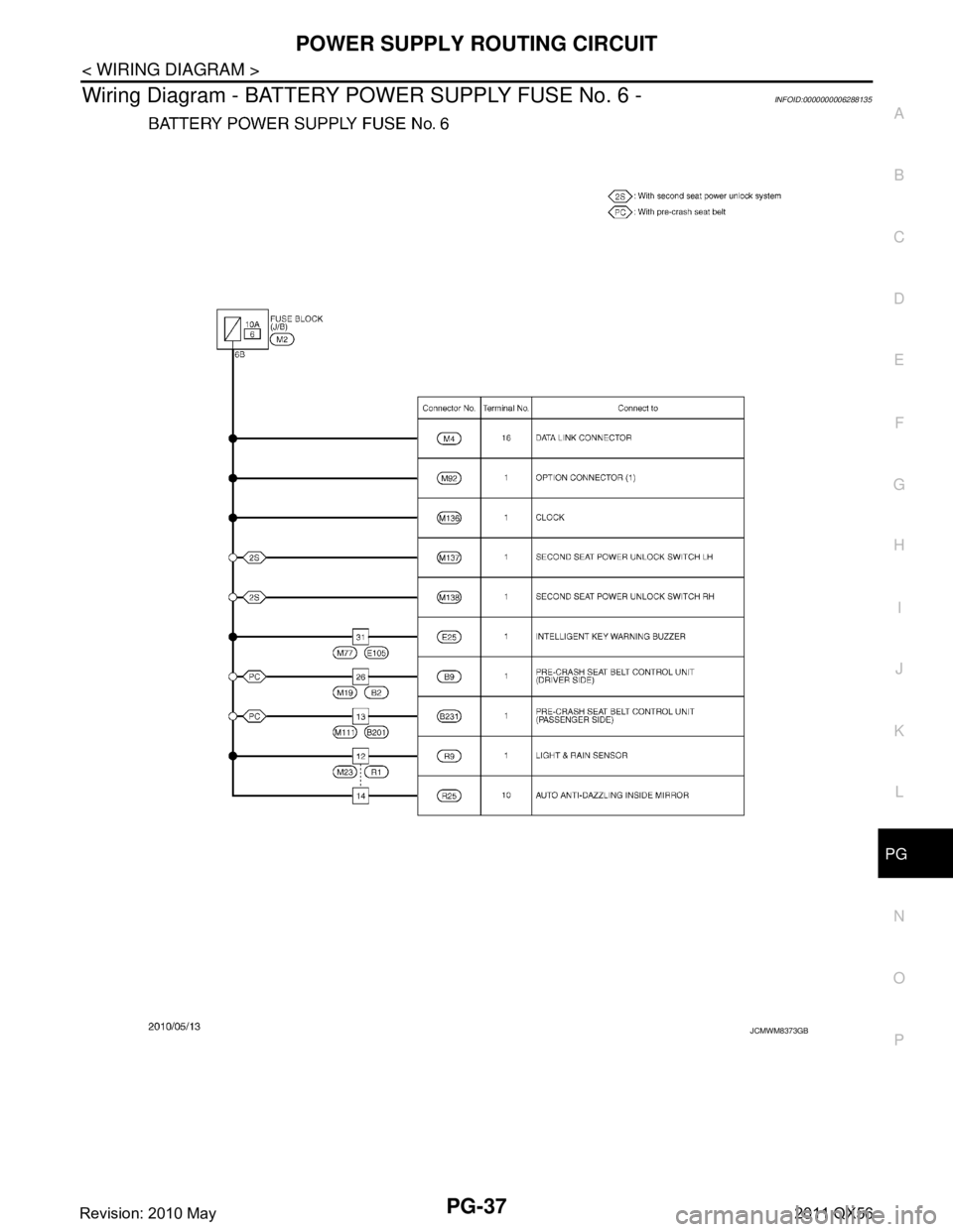
Wiring Diagram - BATTERY POWER SUPPLY FUSE No. 6 -INFOID:0000000006288135
JCMWM8373GB
Revision: 2010 May2011 QX56
Page 3962 of 5598
PG
POWER SUPPLY ROUTING CIRCUITPG-43
< WIRING DIAGRAM >
C
DE
F
G H
I
J
K L
B A
O P
N
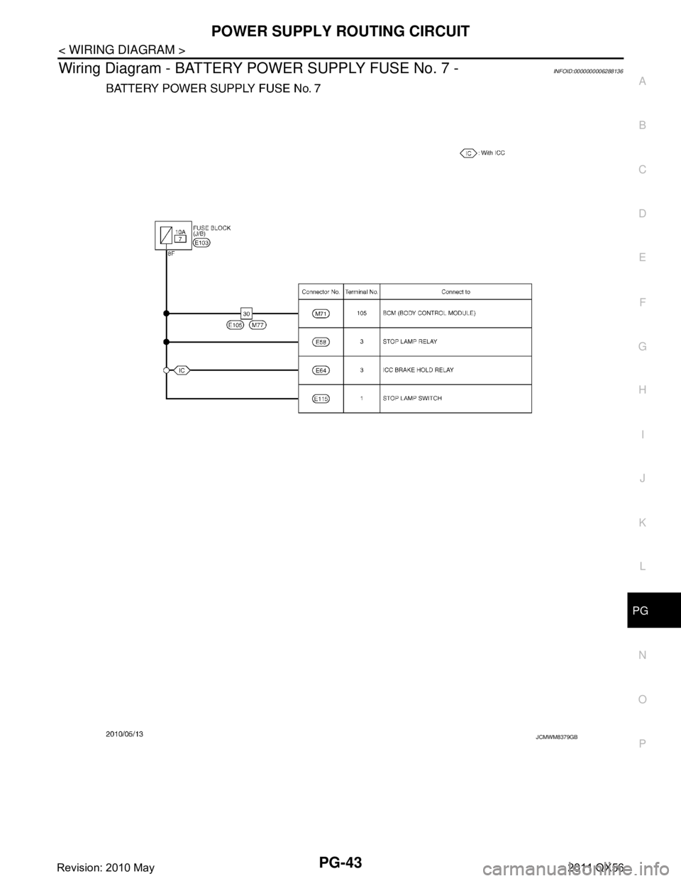
Wiring Diagram - BATTERY POWER SUPPLY FUSE No. 7 -INFOID:0000000006288136
JCMWM8379GB
Revision: 2010 May2011 QX56
Page 3965 of 5598
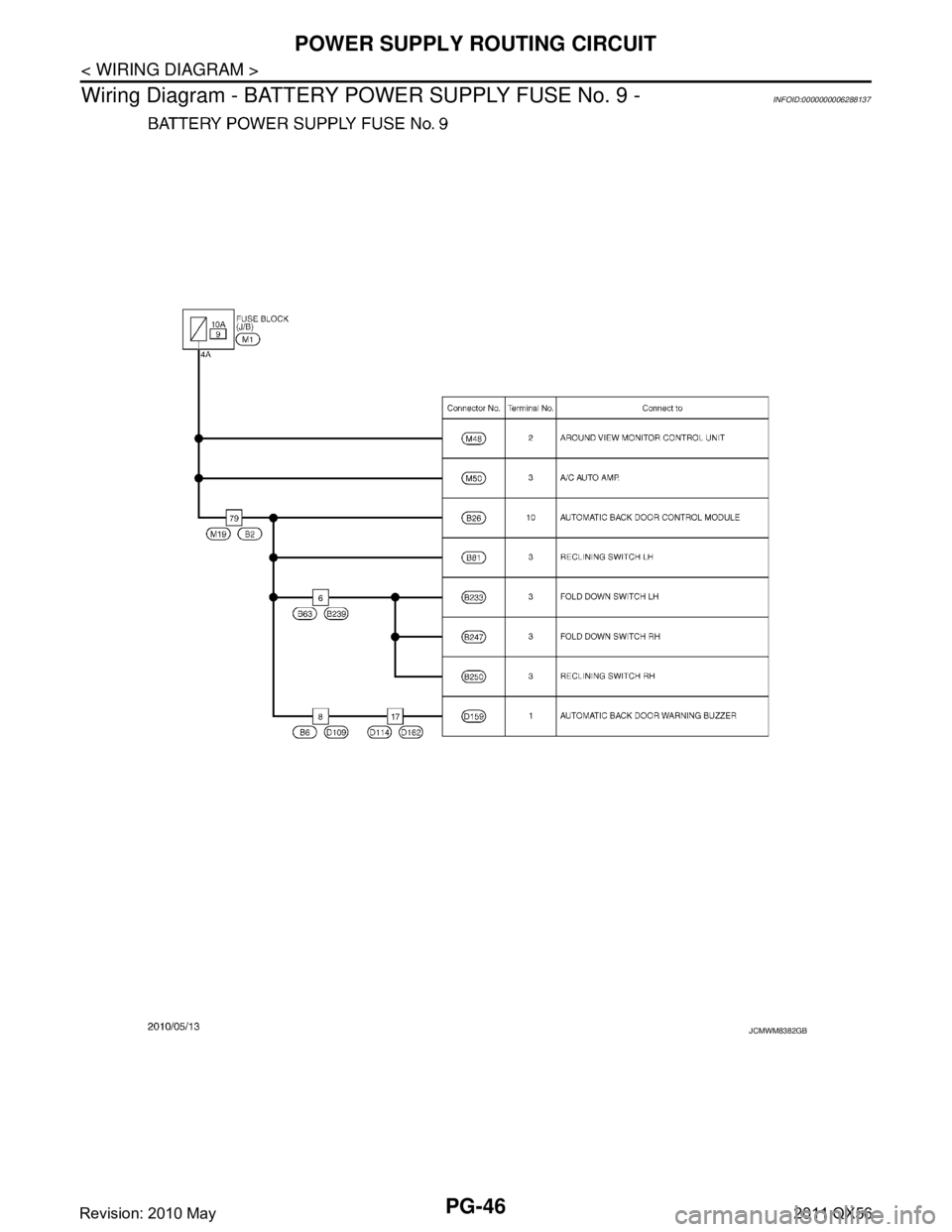
PG-46
< WIRING DIAGRAM >
POWER SUPPLY ROUTING CIRCUIT
Wiring Diagram - BATTERY PO WER SUPPLY FUSE No. 9 -
INFOID:0000000006288137
JCMWM8382GB
Revision: 2010 May2011 QX56