Page 1935 of 5598
SERVICE DATA AND SPECIFICATIONS (SDS)
DLN-133
< SERVICE DATA AND SPECIFICATIONS (SDS) [FRONT PROPELLER SHAFT: 2F P15]
C
EF
G H
I
J
K L
M A
B
DLN
N
O P
SERVICE DATA AND SPECIFICATIONS (SDS)
SERVICE DATA AND SPECIFICATIONS (SDS)
General SpecificationINFOID:0000000006222360
Propeller Shaft RunoutINFOID:0000000006222361
Unit: mm (in)
Journal Axial PlayINFOID:0000000006222362
Unit: mm (in)
Applied model 4WD
VK56VD A/T
Propeller shaft model 2F P15
Number of joints 2
Type of journal bearings 1st joint Shell type
2rd joint Shell type
Coupling method with transfer Flange type
Coupling method with rear final drive Flange type
Shaft length (Spider to spider) 729 mm (28.70 in)
Shaft outer diameter 68.9 mm (2.713 in)
Item Limit
Propeller shaft runout 1.0 (0.04)
Item Standard
Journal axial play 0.06 (0.0024)
Revision: 2010 May2011 QX56
Page 1942 of 5598
DLN-140
< SERVICE DATA AND SPECIFICATIONS (SDS) [REAR PROPELLER SHAFT: 2F P26]
SERVICE DATA AND SPECIFICATIONS (SDS)
SERVICE DATA AND SPECIFICATIONS (SDS)
SERVICE DATA AND SPECIFICATIONS (SDS)
General SpecificationINFOID:0000000006222369
Propeller Shaft RunoutINFOID:0000000006222370
Unit: mm (in)
Journal Axial PlayINFOID:0000000006222371
Unit: mm (in)
Applied model 4WD
VK56VD A/T
Propeller shaft model 2F P26
Number of joints 2
Type of journal bearings 1st joint Shell type
2rd joint Shell type
Coupling method with transfer Flange type
Coupling method with rear final drive Flange type
Shaft length (Spider to spider) 1168mm (45.98 in)
Shaft outer diameter 101.6 mm (4.00 in)
Item Limit
Propeller shaft runout 1.0 (0.04)
Item Standard
Journal axial play 0 (0)
Revision: 2010 May2011 QX56
Page 1987 of 5598
![INFINITI QX56 2011 Factory Service Manual
SERVICE DATA AND SPECIFICATIONS (SDS)
DLN-185
< SERVICE DATA AND SPECIFICATIONS (SDS) [FRONT FINAL DRIVE: R180A]
C
EF
G H
I
J
K L
M A
B
DLN
N
O P
SERVICE DATA AND SPECIFICATIONS (SDS)
SERVICE DATA A INFINITI QX56 2011 Factory Service Manual
SERVICE DATA AND SPECIFICATIONS (SDS)
DLN-185
< SERVICE DATA AND SPECIFICATIONS (SDS) [FRONT FINAL DRIVE: R180A]
C
EF
G H
I
J
K L
M A
B
DLN
N
O P
SERVICE DATA AND SPECIFICATIONS (SDS)
SERVICE DATA A](/manual-img/42/57033/w960_57033-1986.png)
SERVICE DATA AND SPECIFICATIONS (SDS)
DLN-185
< SERVICE DATA AND SPECIFICATIONS (SDS) [FRONT FINAL DRIVE: R180A]
C
EF
G H
I
J
K L
M A
B
DLN
N
O P
SERVICE DATA AND SPECIFICATIONS (SDS)
SERVICE DATA AND SPECIFICATIONS (SDS)
General SpecificationsINFOID:0000000006222401
Drive Gear RunoutINFOID:0000000006222402
Unit: mm (in)
Preload TorqueINFOID:0000000006222403
Unit: N·m (kg-m, in-lb)
BacklashINFOID:0000000006222404
Unit: mm (in)
Companion Flange RunoutINFOID:0000000006222405
Unit: mm (in)
Applied model 4WD
VK56VD A/T
Final drive model R180A
Gear ratio 2.937
Number of teeth (Drive gear/Drive pinion) 47/16
Oil capacity (Approx.) (US pt, lmp pt)0.75 (1-5/8, 1-3/8)
Number of pinion gears 4
Drive pinion adjustment spacer type Collapsible
Item Limit
Drive gear back face runout 0.05 (0.0020)
Item Standard
Pinion bearing (P
1) 1.08 – 1.66 (0.11 – 0.16, 10 – 14)
Side bearing (P
2) 0.59 – 1.08 (0.06 – 0.11, 6 – 9)
Side bearing to pinion bearing (Total preload)
(Total preload = P
1 + P2) 1.67 – 2.74 (0.17 – 0.27, 15 – 24)
Item Standard
Drive gear to drive pinion gear 0.10 – 0.15 (0.0039 – 0.0059)
Item Limit
Companion flange face 0.10 (0.004)
Inner side of the companion flange 0.10 (0.004)
Revision: 2010 May2011 QX56
Page 2024 of 5598
![INFINITI QX56 2011 Factory Service Manual
DLN-222
< SERVICE DATA AND SPECIFICATIONS (SDS) [REAR FINAL DRIVE: R230]
SERVICE DATA AND SPECIFICATIONS (SDS)
SERVICE DATA AND SPECIFICATIONS (SDS)
SERVICE DATA AND SPECIFICATIONS (SDS)
General Spec INFINITI QX56 2011 Factory Service Manual
DLN-222
< SERVICE DATA AND SPECIFICATIONS (SDS) [REAR FINAL DRIVE: R230]
SERVICE DATA AND SPECIFICATIONS (SDS)
SERVICE DATA AND SPECIFICATIONS (SDS)
SERVICE DATA AND SPECIFICATIONS (SDS)
General Spec](/manual-img/42/57033/w960_57033-2023.png)
DLN-222
< SERVICE DATA AND SPECIFICATIONS (SDS) [REAR FINAL DRIVE: R230]
SERVICE DATA AND SPECIFICATIONS (SDS)
SERVICE DATA AND SPECIFICATIONS (SDS)
SERVICE DATA AND SPECIFICATIONS (SDS)
General SpecificationINFOID:0000000006222430
Drive Gear RunoutINFOID:0000000006222431
Unit: mm (in)
Side Gear ClearanceINFOID:0000000006222432
Unit: mm (in)
Preload TorqueINFOID:0000000006222433
BacklashINFOID:0000000006222434
Unit: mm (in)
Companion Flange RunoutINFOID:0000000006222435
Unit: mm (in)
Applied model 2WD 4WD
VK56VDA/T
Final drive model R230
Gear ratio 2.937
Number of teeth (Drive gear/Drive pinion) 47/16
Oil capacity (Approx.) (US pt, lmp pt)1.75 (3-3/4, 3-1/8)
Number of pinion gears 2
Drive pinion adjustment spacer type Collapsible
Item Runout limit
Drive gear back face 0.05 (0.0020) or less
Item Specification
Side gear back clearance
(Clearance limit between side gear and differential case for adjusting
side gear backlash) 0.20 (0.0079) or less
(Each gear should rotate smoothly without excessive resis-
tance during differential motion.)
Item Specification
Drive pinion bearing preload torque 1.76 − 2.65 N·m (0.18 − 0.27 kg −m, 16 − 23 in-lb)
Side bearing preload torque (reference value determined by drive
gear bolt pulling force) 0.29
− 1.47 N·m (0.03 − 0.14 kg −m, 3 − 13 in-lb)
Total preload torque
(Total preload torque = drive pinion bearing preload torque + Side
bearing preload torque) 2.06
− 4.12 N·m (0.21 − 0.42 kg −m, 19 − 36 in-lb)
Item Specification
Drive gear to drive pinion gear 0.13 − 0.18 (0.0051 − 0.0070)
Item Runout limit
Inner side of the companion flange 0.08 (0.0031) or less
Revision: 2010 May2011 QX56
Page 2617 of 5598

OIL PAN (LOWER) AND OIL STRAINEREM-55
< REMOVAL AND INSTALLATION >
C
DE
F
G H
I
J
K L
M A
EM
NP
O
Removal and InstallationINFOID:0000000006289560
REMOVAL
WARNING:
To avoid the danger of being scalded, never
drain engine oil when engine is hot.
1. Drain engine oil. Refer to LU-8, "
Draining".
2. Remove protector A and protector B. Refer to SCS-32, "
FRONT TUBE ASSEMBLY : Exploded View".
3. Remove front suspension rear cross member. Refer to TM-205, "
2WD : Exploded View" (2WD models) or
TM-208, "
4WD : Exploded View" (4WD models).
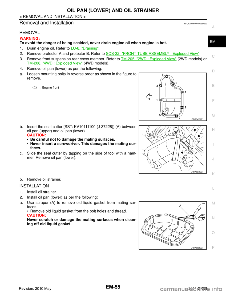
4. Remove oil pan (lower) as per the following:
a. Loosen mounting bolts in reverse order as shown in the figure to remove.
b. Insert the seal cutter [SST: KV10111100 (J-37228)] (A) between oil pan (upper) and oil pan (lower).
CAUTION:
Be careful not to damage the mating surfaces.
Never insert a screwdriver. This damages the mating sur-faces.
c. Slide the seal cutter by tapping on the side of tool with a ham- mer. Remove oil pan (lower).
5. Remove oil strainer.
INSTALLATION
1. Install oil strainer.
2. Install oil pan (lower) as per the following:
a. Use scraper (A) to remove old liquid gasket from mating sur- faces.
Remove old liquid gasket from the bolt holes and thread.
CAUTION:
Never scratch or damage th e mating surfaces when clean-
ing off old liquid gasket.
: Engine front
JPBIA3495ZZ
JPBIA0276ZZ
JPBIA0025ZZ
Revision: 2010 May2011 QX56
Page 2620 of 5598

EM-58
< REMOVAL AND INSTALLATION >
OIL PAN (UPPER)
Removal and Installation
INFOID:0000000006289563
REMOVAL
WARNING:
To avoid the danger of being scalded, never drain engine oil when engine is hot.
1. Remove oil filter. Refer to LU-9, "
Removal and Installation".
2. Remove oil cooler. Refer to LU-11, "
Exploded View".
3. Move A/C compressor to the position without the hindrance for work. Refer to HA-30, "
Exploded View".
4. Remove oil level gauge and oil level gauge guide.
5. Remove oil pressure switch and oil temperature sensor if necessary.
6. Remove rear plate cover.
7. Remove protector A and protector B. Refer to SCS-32, "
FRONT TUBE ASSEMBLY : Exploded View".
8. Remove front suspension rear cross member. Refer to TM-205, "
2WD : Exploded View" (2WD models) or
TM-208, "
4WD : Exploded View" (4WD models).
9. Remove steering gear assembly. Refer to ST-41, "
Exploded View".
10. Remove front final drive assembly. Refer to DLN-162, "
Exploded View".
11. Remove oil pan (lower). Refer to EM-54, "
Exploded View".
12. Remove oil strainer. Refer to EM-54, "
Exploded View".
13. Remove bolts fixing oil pan (upper) to transmission assembly.
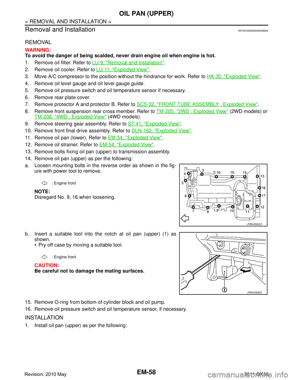
14. Remove oil pan (upper) as per the following:
a. Loosen mounting bolts in the reverse order as shown in the fig- ure with power tool to remove.
NOTE:
Disregard No. 9, 16 when loosening.
b. Insert a suitable tool into the notch at oil pan (upper) (1) as shown.
Pry off case by moving a suitable tool.
CAUTION:
Be careful not to damage the mating surfaces.
15. Remove O-ring from bottom of cylinder block and oil pump.
16. Remove oil pressure switch and oil temperature sensor, if necessary.
INSTALLATION
1. Install oil pan (upper) as per the following:
: Engine front
JPBIA3502ZZ
: Engine front
JPBIA2299ZZ
Revision: 2010 May2011 QX56
Page 2659 of 5598

OIL SEALEM-97
< REMOVAL AND INSTALLATION >
C
DE
F
G H
I
J
K L
M A
EM
NP
O
REAR OIL SEAL : Removal and InstallationINFOID:0000000006289575
REMOVAL
1. Remove transmission assembly. Refer to
TM-205, "2WD : Exploded View" (2WD models) or TM-208,
"4WD : Exploded View" (4WD models).
2. Remove drive plate. Refer to EM-106, "
Exploded View".
3. Remove rear oil seal with a suitable tool. CAUTION:
Be careful not to damage crankshaft and cylinder block.
INSTALLATION
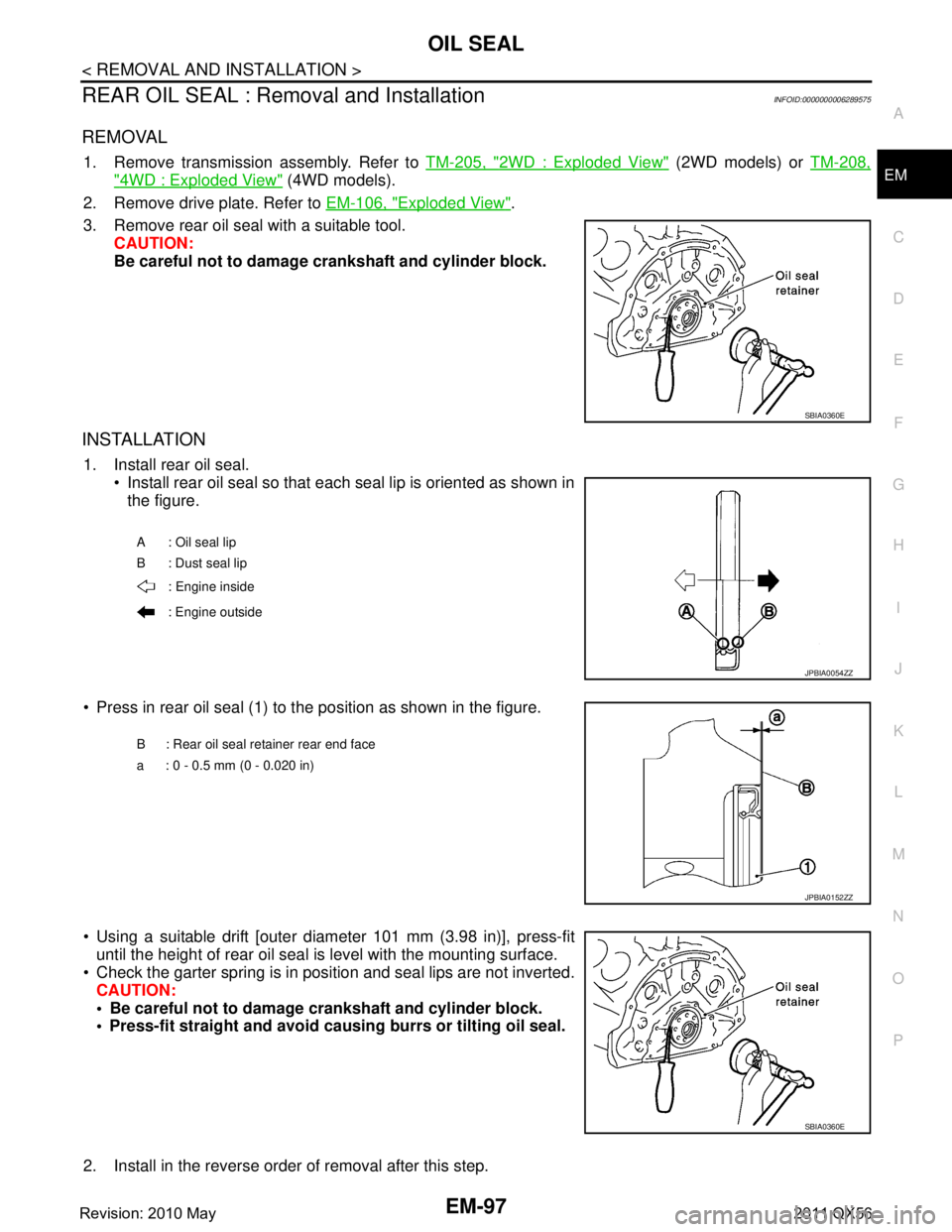
1. Install rear oil seal. Install rear oil seal so that each seal lip is oriented as shown in
the figure.
Press in rear oil seal (1) to the position as shown in the figure.
Using a suitable drift [outer diameter 101 mm (3.98 in)], press-fit until the height of rear oil seal is level with the mounting surface.
Check the garter spring is in position and seal lips are not inverted. CAUTION:
Be careful not to damage crankshaft and cylinder block.
Press-fit straight and avoid cau sing burrs or tilting oil seal.
2. Install in the reverse order of removal after this step.
SBIA0360E
A : Oil seal lip
B : Dust seal lip : Engine inside
: Engine outside
JPBIA0054ZZ
B : Rear oil seal retainer rear end face
a : 0 - 0.5 mm (0 - 0.020 in)
JPBIA0152ZZ
SBIA0360E
Revision: 2010 May2011 QX56
Page 2661 of 5598

ENGINE ASSEMBLYEM-99
< UNIT REMOVAL AND INSTALLATION >
C
DE
F
G H
I
J
K L
M A
EM
NP
O
4WD models
Removal and InstallationINFOID:0000000006289577
WARNING:
Situate the vehicle on a flat and solid surface.
Place chocks at the front
and back of rear wheels.
For engines not equipped with engi ne slingers, attach proper slingers and bolts described in PARTS
CATALOG.
CAUTION:
Always be careful to work safely, and avo id forceful or uninstructed operations.
Never start working until exhaust system and engine coolant are cool enough.
If items or work required are not covered by th e engine section, refer to the applicable sections.
Always use the support poin t specified for lifting.
Use either 2-pole lift type or separate type lift as much as possible. If board-on type is used for
unavoidable reasons, support at r ear axle jacking point with transmi ssion jack or similar tool before
starting work, in preparat ion for the backward shift of the center of gravity.
For supporting points fo r lifting and jacking point at rear axle, refer to GI-32, "
Garage Jack and
Safety Stand".
NOTE:
When removing/installing only the engine mounting, the hold engine assembly as instructed bellow:
1. Remove hood assembly. Refer to DLK-215, "
Exploded View".
2. Remove the following components and related parts: Battery. Refer to PG-164, "
Exploded View".
Battery tray.
Power steering reservoir tank bracket. Refer to ST-54, "
Exploded View".
Air cleaner case assembly and air duct. Refer to EM-27, "
Exploded View".
JPBIA4256GB
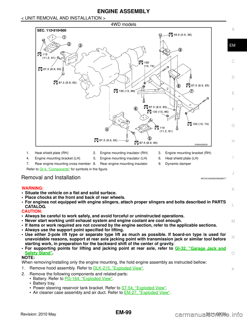
1. Heat shield plate (RH) 2. Engine mounting insulator (RH) 3. Engine mounting bracket (RH)
4. Engine mounting bracket (LH) 5. Engine mounting insulator (LH) 6. Heat shield plate (LH)
7. Rear engine mounting cross member 8. Rear engine mounting insulator 9. Dynamic damper
Refer to GI-4, "
Components" for symbols in the figure.
Revision: 2010 May2011 QX56