2011 INFINITI QX56 4WD
[x] Cancel search: 4WDPage 2662 of 5598

EM-100
< UNIT REMOVAL AND INSTALLATION >
ENGINE ASSEMBLY
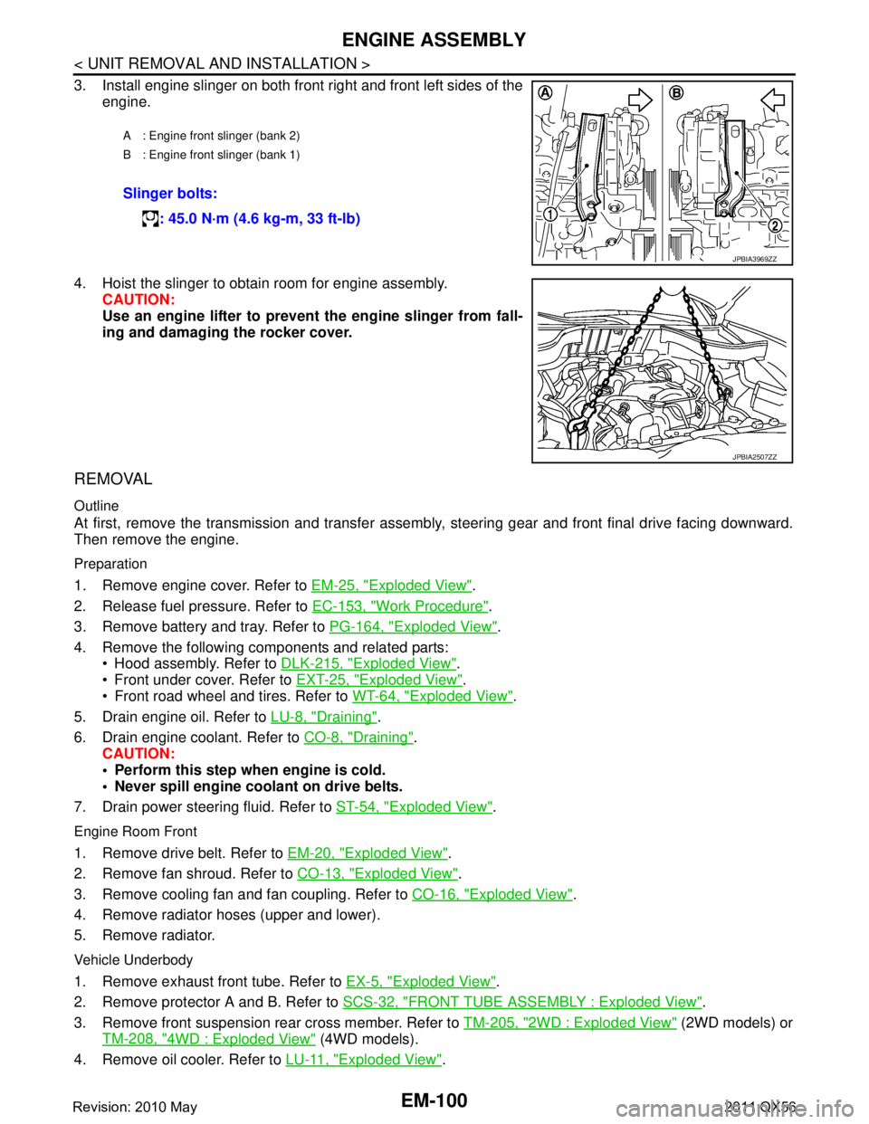
3. Install engine slinger on both front right and front left sides of theengine.
4. Hoist the slinger to obtain room for engine assembly. CAUTION:
Use an engine lifter to prevent the engine slinger from fall-
ing and damaging the rocker cover.
REMOVAL
Outline
At first, remove the transmission and transfer assemb ly, steering gear and front final drive facing downward.
Then remove the engine.
Preparation
1. Remove engine cover. Refer to EM-25, "Exploded View".
2. Release fuel pressure. Refer to EC-153, "
Work Procedure".
3. Remove battery and tray. Refer to PG-164, "
Exploded View".
4. Remove the following components and related parts: Hood assembly. Refer to DLK-215, "
Exploded View".
Front under cover. Refer to EXT-25, "
Exploded View".
Front road wheel and tires. Refer to WT-64, "
Exploded View".
5. Drain engine oil. Refer to LU-8, "
Draining".
6. Drain engine coolant. Refer to CO-8, "
Draining".
CAUTION:
Perform this step when engine is cold.
Never spill engine coolant on drive belts.
7. Drain power steering fluid. Refer to ST-54, "
Exploded View".
Engine Room Front
1. Remove drive belt. Refer to EM-20, "Exploded View".
2. Remove fan shroud. Refer to CO-13, "
Exploded View".
3. Remove cooling fan and fan coupling. Refer to CO-16, "
Exploded View".
4. Remove radiator hoses (upper and lower).
5. Remove radiator.
Vehicle Underbody
1. Remove exhaust front tube. Refer to EX-5, "Exploded View".
2. Remove protector A and B. Refer to SCS-32, "
FRONT TUBE ASSEMBLY : Exploded View".
3. Remove front suspension rear cross member. Refer to TM-205, "
2WD : Exploded View" (2WD models) or
TM-208, "
4WD : Exploded View" (4WD models).
4. Remove oil cooler. Refer to LU-11, "
Exploded View".
A : Engine front slinger (bank 2)
B : Engine front slinger (bank 1)
Slinger bolts:
: 45.0 N·m (4.6 kg-m, 33 ft-lb)
JPBIA3969ZZ
JPBIA2507ZZ
Revision: 2010 May2011 QX56
Page 2663 of 5598

ENGINE ASSEMBLYEM-101
< UNIT REMOVAL AND INSTALLATION >
C
DE
F
G H
I
J
K L
M A
EM
NP
O
5. Remove A/T assembly. Refer to
TM-205, "2WD : Exploded View" (2WD models) or TM-208, "4WD :
Exploded View" (4WD models).
6. Remove steering gear assembly. Refer to ST-41, "
Exploded View".
7. Remove front final drive assembly. Refer to DLN-162, "
Exploded View".
8. Remove exhaust manifold. Refer to EM-40, "
Exploded View".
9. Remove alternator. Refer to CHG-25, "
Exploded View".
Engine Room LH
1. Remove air cleaner and air duct. Refer to EM-27, "Exploded View".
2. Remove A/C compressor. Refer to HA-30, "
Exploded View".
3. Disconnect fuel feed hose and EVAP hose. Refer to EM-43, "
Exploded View".
CAUTION:
Fit plugs onto disconnected hoses to prevent fuel leakage.
Engine Room RH
1. Remove power steering oil pump and reservoir tank. Refer to ST-48, "Exploded View".
2. Disconnect heater hose at heater core side, and fit a plug onto hose end to prevent engine coolant leak-
age.
3. Disconnect ground cable.
4. Disconnect all clips and connectors of the engine harness from vehicle side.
Removal Work
1. Install alternator bracket. Refer to CHG-25, "Exploded View".
Temporarily tighten mounting bolts.
2. Remove intake manifold. Refer to EM-30, "
Exploded View".
3. Remove starter motor. Refer to STR-17, "
Exploded View".
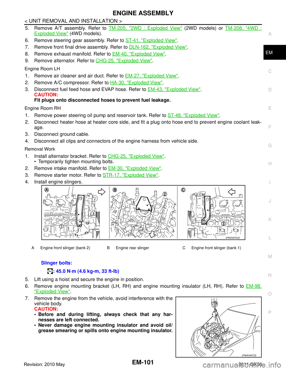
4. Install engine slingers.
5. Lift using a hoist and secure the engine in position.
6. Remove engine mounting bracket (LH, RH) and engine mounting insulator (LH, RH). Refer to EM-98,
"Exploded View".
7. Remove the engine from the vehi cle, avoid interference with the
vehicle body.
CAUTION:
Before and during lifting, always check that any har-
nesses are left connected.
Never damage engine mounti ng insulator and avoid oil/
grease smearing or spills onto engine mounting insulator.
A Engine front slinger (bank 2) B Engine rear slinger C Engine front slinger (bank 1)
Slinger bolts:
: 45.0 N·m (4.6 kg-m, 33 ft-lb)
JPBIA3970ZZ
JPBIA3497ZZ
Revision: 2010 May2011 QX56
Page 2901 of 5598

FAX-1
TRANSMISSION & DRIVELINE
CEF
G H
I
J
K L
M
SECTION FA X
A
B
FA X
N
O P
CONTENTS
FRONT AXLE
2WD
PRECAUTION ................ ...............................
3
PRECAUTIONS .............................................. .....3
Precaution for Supplemental Restraint System
(SRS) "AIR BAG" and "SEAT BELT PRE-TEN-
SIONER" ............................................................. ......
3
Precaution Necessary for Steering Wheel Rota-
tion after Battery Disconnect .....................................
3
PREPARATION ............................................5
PREPARATION .............................................. .....5
Commercial Service Tools .................................. ......5
SYMPTOM DIAGNOSIS ...............................6
NOISE, VIBRATION AND HARSHNESS
(NVH) TROUBLESHOOTING ........................ .....
6
NVH Troubleshooting Chart ................................ ......6
PERIODIC MAINTENANCE ..........................7
FRONT WHEEL HUB AND KNUCKLE ......... .....7
Inspection ............................................................ ......7
REMOVAL AND INSTALLATION ................8
FRONT WHEEL HUB AND KNUCKLE ......... .....8
Exploded View .................................................... ......8
Removal and Installation ...........................................8
Inspection ..................................................................9
SERVICE DATA AND SPECIFICATIONS
(SDS) ......... ................................. ..................
10
SERVICE DATA AND SPECIFICATIONS
(SDS) .............................................................. ....
10
Wheel Hub and Bearing Assembly ..................... ....10
4WDPRECAUTION ...............
...............................
11
PRECAUTIONS .................................................11
Precaution for Supplemental Restraint System
(SRS) "AIR BAG" and "SEAT BELT PRE-TEN-
SIONER" ............................................................. ....
11
Precaution Necessary for Steering Wheel Rota-
tion after Battery Disconnect ...................................
11
Precautions for Drive Shaft ......................................12
PREPARATION ...........................................13
PREPARATION .................................................13
Special Service Tools .......................................... ....13
Commercial Service Tools .......................................13
SYMPTOM DIAGNOSIS ..............................15
NOISE, VIBRATION AND HARSHNESS
(NVH) TROUBLESHOOTING ...........................
15
NVH Troubleshooting Chart ................................ ....15
PERIODIC MAINTENANCE ........................16
FRONT WHEEL HUB AND KNUCKLE ............16
Inspection ............................................................ ....16
FRONT DRIVE SHAFT .....................................17
Inspection ................................................................17
REMOVAL AND INSTALLATION ...............18
FRONT WHEEL HUB AND KNUCKLE ............18
Exploded View ..................................................... ....18
Removal and Installation .........................................18
Inspection ................................................................20
FRONT DRIVE SHAFT BOOT ..........................21
Exploded View .........................................................21
Removal and Installation .........................................21
Inspection ................................................................21
FRONT DRIVE SHAFT .....................................22
Revision: 2010 May2011 QX56
Page 2911 of 5598
![INFINITI QX56 2011 Factory Service Manual
PRECAUTIONSFAX-11
< PRECAUTION > [4WD]
C
EF
G H
I
J
K L
M A
B
FA X
N
O P
PRECAUTION
PRECAUTIONS
Precaution for Supplemental Restraint System (SRS) "AIR BAG" and "SEAT BELT
PRE-TENSIONER"
INFOID:000 INFINITI QX56 2011 Factory Service Manual
PRECAUTIONSFAX-11
< PRECAUTION > [4WD]
C
EF
G H
I
J
K L
M A
B
FA X
N
O P
PRECAUTION
PRECAUTIONS
Precaution for Supplemental Restraint System (SRS) "AIR BAG" and "SEAT BELT
PRE-TENSIONER"
INFOID:000](/manual-img/42/57033/w960_57033-2910.png)
PRECAUTIONSFAX-11
< PRECAUTION > [4WD]
C
EF
G H
I
J
K L
M A
B
FA X
N
O P
PRECAUTION
PRECAUTIONS
Precaution for Supplemental Restraint System (SRS) "AIR BAG" and "SEAT BELT
PRE-TENSIONER"
INFOID:0000000006271941
The Supplemental Restraint System such as “A IR BAG” and “SEAT BELT PRE-TENSIONER”, used along
with a front seat belt, helps to reduce the risk or severi ty of injury to the driver and front passenger for certain
types of collision. This system includes seat belt switch inputs and dual stage front air bag modules. The SRS
system uses the seat belt switches to determine the front air bag deployment, and may only deploy one front
air bag, depending on the severity of a collision and whether the front occupants are belted or unbelted.
Information necessary to service the system safely is included in the “SRS AIR BAG” and “SEAT BELT” of this
Service Manual.
WARNING:
To avoid rendering the SRS inoper ative, which could increase the risk of personal injury or death in
the event of a collision that would result in air ba g inflation, all maintenance must be performed by
an authorized NISSAN/INFINITI dealer.
Improper maintenance, including in correct removal and installation of the SRS, can lead to personal
injury caused by unintentional act ivation of the system. For removal of Spiral Cable and Air Bag
Module, see the “SRS AIR BAG”.
Do not use electrical test equipm ent on any circuit related to the SRS unless instructed to in this
Service Manual. SRS wiring harnesses can be identi fied by yellow and/or orange harnesses or har-
ness connectors.
PRECAUTIONS WHEN USING POWER TOOLS (AIR OR ELECTRIC) AND HAMMERS
WARNING:
When working near the Air Bag Diagnosis Sensor Unit or other Air Bag System sensors with the
ignition ON or engine running, DO NOT use air or electric power tools or strike near the sensor(s)
with a hammer. Heavy vibration could activate the sensor(s) and deploy the air bag(s), possibly
causing serious injury.
When using air or electric power tools or hammers , always switch the ignition OFF, disconnect the
battery, and wait at least 3 minutes before performing any service.
Precaution Necessary for Steering Wh eel Rotation after Battery Disconnect
INFOID:0000000006271943
NOTE:
Before removing and installing any control units, first tu rn the push-button ignition switch to the LOCK posi-
tion, then disconnect both battery cables.
After finishing work, confirm that all control unit connectors are connected properly, then re-connect both
battery cables.
Always use CONSULT-III to perform self-diagnosis as a part of each function inspection after finishing work.
If a DTC is detected, perform trouble diagnos is according to self-diagnosis results.
For vehicle with steering lock unit, if the battery is disconnected or discharged, the steering wheel will lock and
cannot be turned.
If turning the steering wheel is required with the batte ry disconnected or discharged, follow the operation pro-
cedure below before starting the repair operation.
OPERATION PROCEDURE
1. Connect both battery cables. NOTE:
Supply power using jumper cables if battery is discharged.
2. Turn the push-button ignition switch to ACC position. (At this time, the steering lock will be released.)
3. Disconnect both battery cables. The steering lock wil l remain released with both battery cables discon-
nected and the steering wheel can be turned.
4. Perform the necessary repair operation.
Revision: 2010 May2011 QX56
Page 2912 of 5598
![INFINITI QX56 2011 Factory Service Manual
FAX-12
< PRECAUTION >[4WD]
PRECAUTIONS
5. When the repair work is completed, re-connect bot
h battery cables. With the brake pedal released, turn
the push-button ignition switch from ACC position to INFINITI QX56 2011 Factory Service Manual
FAX-12
< PRECAUTION >[4WD]
PRECAUTIONS
5. When the repair work is completed, re-connect bot
h battery cables. With the brake pedal released, turn
the push-button ignition switch from ACC position to](/manual-img/42/57033/w960_57033-2911.png)
FAX-12
< PRECAUTION >[4WD]
PRECAUTIONS
5. When the repair work is completed, re-connect bot
h battery cables. With the brake pedal released, turn
the push-button ignition switch from ACC position to ON position, then to LOCK position. (The steering
wheel will lock when the push-button igniti on switch is turned to LOCK position.)
6. Perform self-diagnosis check of all control units using CONSULT-III.
Precautions for Drive ShaftINFOID:0000000006225390
Observe the following precautions when disassembling and assembling drive shaft.
- Never disassemble joint sub-assembly because it is non-overhaul parts.
- Perform work in a location which is as dust-free as possible.
- Clean the parts, before disassembling and assembling.
- Prevent the entry of foreign objects dur ing disassembly of the service location.
- Reassemble disassembled parts carefully in the correct order. If work is interrupted, a clean cover must be placed over parts.
- Use paper waste. Fabric shop cloths must not be used because of the danger of lint adhering to parts.
- Clean disassembled parts (except for rubber parts) with kerosene which shall be removed by blowing with
air or wiping with paper waste.
Revision: 2010 May2011 QX56
Page 2913 of 5598
![INFINITI QX56 2011 Factory Service Manual
PREPARATIONFAX-13
< PREPARATION > [4WD]
C
EF
G H
I
J
K L
M A
B
FA X
N
O P
PREPARATION
PREPARATION
Special Service ToolsINFOID:0000000006225391
The actual shapes of Kent-Moore t ools may differ from t INFINITI QX56 2011 Factory Service Manual
PREPARATIONFAX-13
< PREPARATION > [4WD]
C
EF
G H
I
J
K L
M A
B
FA X
N
O P
PREPARATION
PREPARATION
Special Service ToolsINFOID:0000000006225391
The actual shapes of Kent-Moore t ools may differ from t](/manual-img/42/57033/w960_57033-2912.png)
PREPARATIONFAX-13
< PREPARATION > [4WD]
C
EF
G H
I
J
K L
M A
B
FA X
N
O P
PREPARATION
PREPARATION
Special Service ToolsINFOID:0000000006225391
The actual shapes of Kent-Moore t ools may differ from those of special service tools illustrated here.
Commercial Service ToolsINFOID:0000000006225392
Tool number
(Kent-Moore No.)
Tool name Description
KV40107300
( − )
Boot band crimping tool Installing boot band
KV40107500
( − )
Drive shaft attachment Removing drive shaft
KV38106300
( − )
Protector
a: 35 mm (1.38 in) dia. Installing drive shaft
ZZA1229D
ZZA1230D
PDIA1183J
Tool name
Description
Power tool Loosening bolts and nuts
Ball joint remover Removing ball joint for steering knuckle Removing hub bolt
PBIC0190E
NT146
Revision: 2010 May2011 QX56
Page 2914 of 5598
![INFINITI QX56 2011 Factory Service Manual
FAX-14
< PREPARATION >[4WD]
PREPARATION
Drive shaft puller Removing drive shaft joint sub assembly
Sliding hummer Removing drive shaft Tool name
Description
JPDIG0152ZZ
ZZA0023D
Revision: 2010 May2 INFINITI QX56 2011 Factory Service Manual
FAX-14
< PREPARATION >[4WD]
PREPARATION
Drive shaft puller Removing drive shaft joint sub assembly
Sliding hummer Removing drive shaft Tool name
Description
JPDIG0152ZZ
ZZA0023D
Revision: 2010 May2](/manual-img/42/57033/w960_57033-2913.png)
FAX-14
< PREPARATION >[4WD]
PREPARATION
Drive shaft puller Removing drive shaft joint sub assembly
Sliding hummer Removing drive shaft Tool name
Description
JPDIG0152ZZ
ZZA0023D
Revision: 2010 May2011 QX56
Page 2915 of 5598
![INFINITI QX56 2011 Factory Service Manual
NOISE, VIBRATION AND HARSHNESS (NVH) TROUBLESHOOTINGFAX-15
< SYMPTOM DIAGNOSIS > [4WD]
C
EF
G H
I
J
K L
M A
B
FA X
N
O P
SYMPTOM DIAGNOSIS
NOISE, VIBRATION AND HARSHN ESS (NVH) TROUBLESHOOTING
NVH Tr INFINITI QX56 2011 Factory Service Manual
NOISE, VIBRATION AND HARSHNESS (NVH) TROUBLESHOOTINGFAX-15
< SYMPTOM DIAGNOSIS > [4WD]
C
EF
G H
I
J
K L
M A
B
FA X
N
O P
SYMPTOM DIAGNOSIS
NOISE, VIBRATION AND HARSHN ESS (NVH) TROUBLESHOOTING
NVH Tr](/manual-img/42/57033/w960_57033-2914.png)
NOISE, VIBRATION AND HARSHNESS (NVH) TROUBLESHOOTINGFAX-15
< SYMPTOM DIAGNOSIS > [4WD]
C
EF
G H
I
J
K L
M A
B
FA X
N
O P
SYMPTOM DIAGNOSIS
NOISE, VIBRATION AND HARSHN ESS (NVH) TROUBLESHOOTING
NVH Troubleshooting ChartINFOID:0000000006225393
Use chart below to find the cause of the symptom. If necessary, repair or replace these parts.
×: ApplicableReference
—
FAX-28—
FAX-18—
FAX-16
NVH in FAX and FSU sections
Refer to FRONT AXLE in this chart.
NVH in WT section
NVH in WT section
Refer to DRIVE SHAFT in this chart.
NVH in BR section
NVH in ST section
Possible cause and SUSPECTED PARTS
Excessive joint angle
Joint sliding resistance
Imbalance
Improper installation, looseness
Parts interference
Wheel bearing damage
FRONT AXLE AND FRONT SUSPENSION
FRONT AXLE
TIRE
ROAD WHEEL
DRIVE SHAFT
BRAKE
STEERING
Symptom DRIVE
SHAFT
Noise
×× ××××× ××
Shake × × ××××× ××
FRONT
AXLE Noise
×××× ×××××
Shake ×××× ×××××
Vibration ×××× × × ×
Shimmy ×× × ×× ××
Judder × × ×× ××
Poor quality ride or handling ×× × ××
Revision: 2010 May2011 QX56