2011 INFINITI QX56 4WD
[x] Cancel search: 4WDPage 3012 of 5598
GI-48
< BASIC INSPECTION >
CONSULT-III/GST CHECKING SYSTEM
CONSULT-III/GST CHECKING SYSTEM
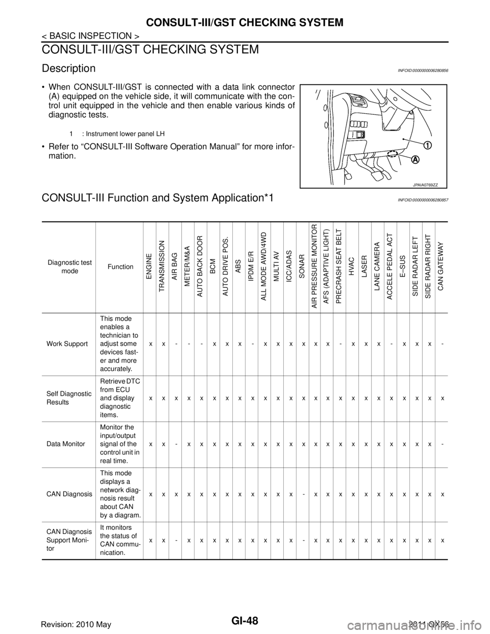
DescriptionINFOID:0000000006280856
When CONSULT-III/GST is connected with a data link connector
(A) equipped on the vehicle side, it will communicate with the con-
trol unit equipped in the vehicle and then enable various kinds of
diagnostic tests.
Refer to “CONSULT-III Software Operation Manual” for more infor- mation.
CONSULT-III Function a nd System Application*1INFOID:0000000006280857
1 : Instrument lower panel LH
JPAIA0769ZZ
Diagnostic test
mode Function
ENGINE
TRANSMISSION AIR BAG
METER/M&A
AUTO BACK DOOR BCM
AUTO DRIVE POS. ABS
IPDM E/R
ALL MODE AWD/4WD MULTI AV
ICC/ADAS SONAR
AIR PRESSURE MONITOR AFS (ADAPTIVE LIGHT)
PRECRASH SEAT BELT HVAC
LASER
LANE CAMERA
ACCELE PEDAL ACT
E–SUS
SIDE RADAR LEFT
SIDE RADAR RIGHT CAN GATEWAY
Work Support This mode
enables a
technician to
adjust some
devices fast-
er and more
accurately.xx - - - xxx - xxxxxx - xxx - xxx -
Self Diagnostic
Results Retrieve DTC
from ECU
and display
diagnostic
items.
xxxxxxxxxxxxxxxxxxxxxxxx
Data Monitor Monitor the
input/output
signal of the
control unit in
real time.xx - xxxxxxxxxxxxxxxxxxxx -
CAN Diagnosis This mode
displays a
network diag-
nosis result
about CAN
by a diagram.xxxxxxxxxxxx -xxxxxxxxxxx
CAN Diagnosis
Support Moni-
tor It monitors
the status of
CAN commu-
nication.
xx - xxxxxxxxx -xxxxxxxxxxx
Revision: 2010 May2011 QX56
Page 3013 of 5598
CONSULT-III/GST CHECKING SYSTEMGI-49
< BASIC INSPECTION >
C
DE
F
G H
I
J
K L
M B
GI
N
O P
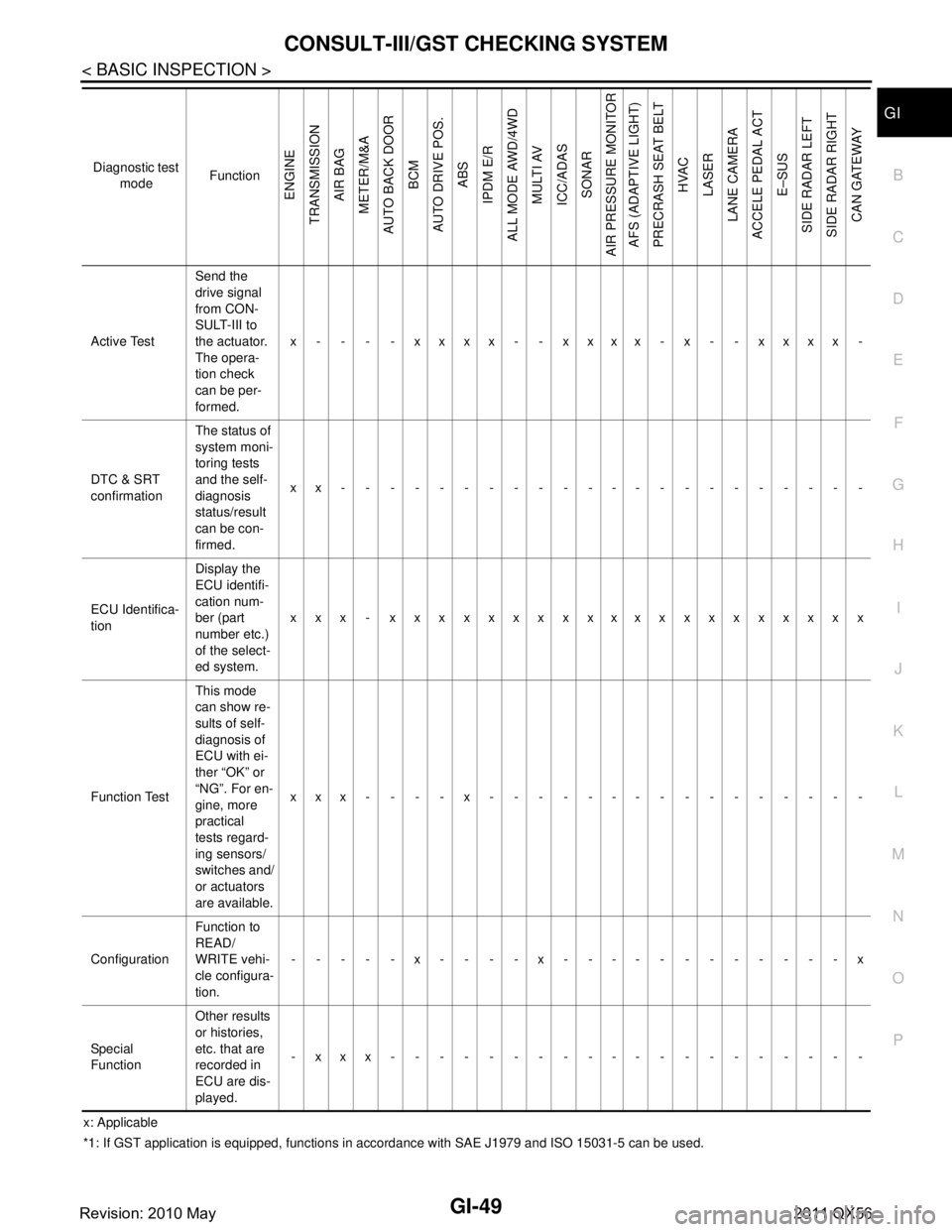
x: Applicable
*1: If GST application is equipped , functions in accordance with SAE J1 979 and ISO 15031-5 can be used.
Active Test
Send the
drive signal
from CON-
SULT-III to
the actuator.
The opera-
tion check
can be per-
formed.x - - - - xxxx - - xxxx - x - - xxxx -
DTC & SRT
confirmation The status of
system moni-
toring tests
and the self-
diagnosis
status/result
can be con-
firmed.
xx----------------------
ECU Identifica-
tion Display the
ECU identifi-
cation num-
ber (part
number etc.)
of the select-
ed system.
xxx - xxxxxxxxxxxxxxxxxxxx
Function Test This mode
can show re-
sults of self-
diagnosis of
ECU with ei-
ther “OK” or
“NG”. For en-
gine, more
practical
tests regard-
ing sensors/
switches and/
or actuators
are available.xxx----x----------------
Configuration Function to
READ/
WRITE vehi-
cle configura-
tion.-----x----x------------x
Special
Function Other results
or histories,
etc. that are
recorded in
ECU are dis-
played.
-xxx--------------------
Diagnostic test
mode Function
ENGINE
TRANSMISSION AIR BAG
METER/M&A
AUTO BACK DOOR
BCM
AUTO DRIVE POS. ABS
IPDM E/R
ALL MODE AWD/4WD
MULTI AV
ICC/ADAS SONAR
AIR PRESSURE MONITOR AFS (ADAPTIVE LIGHT)
PRECRASH SEAT BELT HVAC
LASER
LANE CAMERA
ACCELE PEDAL ACT E–SUS
SIDE RADAR LEFT
SIDE RADAR RIGHT CAN GATEWAY
Revision: 2010 May2011 QX56
Page 3414 of 5598
IP-24
< REMOVAL AND INSTALLATION >
CENTER CONSOLE ASSEMBLY
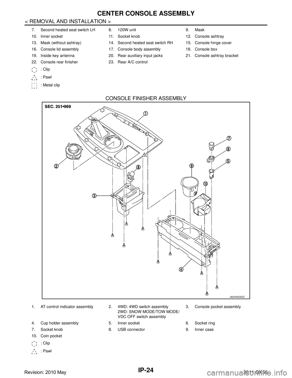
CONSOLE FINISHER ASSEMBLY
7. Second heated seat switch LH 8. 120W unit 9. Mask
10. Inner socket 11. Socket knob 12. Console ashtray
13. Mask (without ashtray) 14. Second heated seat switch RH 15. Console hinge cover
16. Console lid assembly 17. Console body assembly 18. Console box
19. Inside key antenna 20. Rear auxiliary input jacks 21. Console ashtray bracket
22. Console rear finisher 23. Rear A/C control: Clip
: Pawl
: Metal clip
JMJIA4230ZZ
1. AT control indicator assembly 2. 4WD: 4WD switch assembly 2WD: SNOW MODE/TOW MODE/
VDC OFF switch assembly3. Console pocket assembly
4. Cup holder assembly 5. Inner socket 6. Socket ring
7. Socket knob 8. USB connector 9. Inner case
10. Coin pocket : Clip
: Pawl
Revision: 2010 May2011 QX56
Page 3418 of 5598
IP-28
< REMOVAL AND INSTALLATION >
CENTER CONSOLE ASSEMBLY
4. Remove console power socket. Refer to PWO-11, "CONSOLE POWER SOCKET (REAR) : Removal and
Installation".
5. Remove 4WD switch assembly (2WD: SNOW MODE/TOW MODE/VDC OFF switch assembly). Refer to DLN-108, "
Removal and Installation".
ASSEMBLY
Assemble in the reverse order of disassembly.
Revision: 2010 May2011 QX56
Page 3422 of 5598

LAN-2
ITS Communication Circuit .....................................58
MAIN LINE BETWEEN ABS AND DLC CIR-
CUIT ...................................................................
60
Diagnosis Procedure ........................................... ...60
MAIN LINE BETWEEN DLC AND E-SUS CIR-
CUIT ...................................................................
61
Diagnosis Procedure ........................................... ...61
MAIN LINE BETWEEN E-SUS AND ADP CIR-
CUIT ...................................................................
62
Diagnosis Procedure ........................................... ...62
MAIN LINE BETWEEN ADP AND PWBD CIR-
CUIT ...................................................................
63
Diagnosis Procedure ........................................... ...63
MAIN LINE BETWEEN RDR-R AND RDR-L
CIRCUIT .............................................................
64
Diagnosis Procedure ........................................... ...64
MAIN LINE BETWEEN RDR-L AND LANE
CIRCUIT .............................................................
65
Diagnosis Procedure ........................................... ...65
MAIN LINE BETWEEN LANE AND APA CIR-
CUIT ...................................................................
67
Diagnosis Procedure ........................................... ...67
ECM BRANCH LINE CIRCUIT ..........................68
Diagnosis Procedure ........................................... ...68
4WD BRANCH LINE CIRCUIT ..........................69
Diagnosis Procedure ........................................... ...69
ABS BRANCH LINE CIRCUIT ..........................70
Diagnosis Procedure ........................................... ...70
TCM BRANCH LINE CIRCUIT ..........................71
Diagnosis Procedure ........................................... ...71
A-BAG BRANCH LINE CIRCUIT ......................72
Diagnosis Procedure ........................................... ...72
AFS BRANCH LINE CIRCUIT ...........................73
Diagnosis Procedure ........................................... ...73
AV BRANCH LINE CIRCUIT .............................74
Diagnosis Procedure ........................................... ...74
BCM BRANCH LINE CIRCUIT ..........................75
Diagnosis Procedure ........................................... ...75
CGW BRANCH LINE CIRCUIT (CAN COM-
MUNICATION CIRCUIT 1) .................................
76
Diagnosis Procedure ........................................... ...76
CGW BRANCH LINE CIRCUIT (CAN COM-
MUNICATION CIRCUIT 2) .................................
77
Diagnosis Procedure ........................................... ...77
DLC BRANCH LINE CIRCUIT ..........................78
Diagnosis Procedure ............................................ ...78
HVAC BRANCH LINE CIRCUIT ........................79
Diagnosis Procedure ............................................ ...79
M&A BRANCH LINE CIRCUIT ..........................80
Diagnosis Procedure ............................................ ...80
STRG BRANCH LINE CIRCUIT ........................81
Diagnosis Procedure ............................................ ...81
TPMS BRANCH LINE CIRCUIT ........................82
Diagnosis Procedure ............................................ ...82
IPDM-E BRANCH LINE CIRCUIT .....................83
Diagnosis Procedure ............................................ ...83
ADP BRANCH LINE CIRCUIT ..........................84
Diagnosis Procedure ............................................ ...84
PSB BRANCH LINE CIRCUIT ..........................85
Diagnosis Procedure ............................................ ...85
E-SUS BRANCH LINE CIRCUIT .......................86
Diagnosis Procedure ............................................ ...86
ICC BRANCH LINE CIRCUIT ............................87
Diagnosis Procedure ............................................ ...87
PWBD BRANCH LINE CIRCUIT .......................88
Diagnosis Procedure ............................................ ...88
RDR-R BRANCH LINE CIRCUIT ......................89
Diagnosis Procedure ............................................ ...89
RDR-L BRANCH LINE CIRCUIT .......................90
Diagnosis Procedure ............................................ ...90
LANE BRANCH LINE CIRCUIT ........................91
Diagnosis Procedure ............................................ ...91
APA BRANCH LINE CIRCUIT ..........................92
Diagnosis Procedure ............................................ ...92
LASER BRANCH LINE CIRCUIT ......................93
Diagnosis Procedure ............................................ ...93
CAN COMMUNICATION CIRCUIT ...................94
Diagnosis Procedure ............................................ ...94
CAN COMMUNICATION CIRCUIT 1 ................96
Diagnosis Procedure ............................................ ...96
CAN COMMUNICATION CIRCUIT 2 ................98
Diagnosis Procedure ............................................ ...98
ITS COMMUNICATION CIRCUIT .....................100
Diagnosis Procedure ............................................ .100
CAN GATEWAY
PRECAUTION ............... ............................
102
PRECAUTIONS .............................................. ..102
Revision: 2010 May2011 QX56
Page 3425 of 5598
LAN
LAN-5
C
DE
F
G H
I
J
K L
B
A
O P
N
Diagnosis Procedure ...........................................
..
178
4WD BRANCH LINE CIRCUIT .........................179
Diagnosis Procedure ........................................... ..179
ABS BRANCH LINE CIRCUIT .........................180
Diagnosis Procedure ........................................... ..180
TCM BRANCH LINE CIRCUIT .........................181
Diagnosis Procedure ........................................... ..181
A-BAG BRANCH LINE CIRCUIT .....................182
Diagnosis Procedure ........................................... ..182
AV BRANCH LINE CIRCUIT ............................183
Diagnosis Procedure ........................................... ..183
BCM BRANCH LINE CIRCUIT ........................184
Diagnosis Procedure ........................................... ..184
DLC BRANCH LINE CIRCUIT .........................185
Diagnosis Procedure ........................................... ..185
HVAC BRANCH LINE CIRCUIT ......................186
Diagnosis Procedure ........................................... ..186
M&A BRANCH LINE CIRCUIT ........................187
Diagnosis Procedure ........................................... ..187
STRG BRANCH LINE CIRCUIT .......................188
Diagnosis Procedure ........................................... ..188
TPMS BRANCH LINE CIRCUIT .......................189
Diagnosis Procedure ........................................... ..189
IPDM-E BRANCH LINE CIRCUIT ....................190
Diagnosis Procedure ........................................... ..190
ADP BRANCH LINE CIRCUIT .........................191
Diagnosis Procedure ........................................... ..191
E-SUS BRANCH LINE CIRCUIT ......................192
Diagnosis Procedure ........................................... ..192
PWBD BRANCH LINE CIRCUIT ......................193
Diagnosis Procedure ........................................... ..193
CAN COMMUNICATION CIRCUIT ..................194
Diagnosis Procedure ........................................... ..194
CAN SYSTEM (TYPE 4)
DTC/CIRCUIT DIAGNOSIS .......................
196
MAIN LINE BETWEEN ABS AND DLC CIR-
CUIT ................................................................ ..
196
Diagnosis Procedure ........................................... ..196
MAIN LINE BETWEEN ADP AND PWBD CIR-
CUIT ..................................................................
197
Diagnosis Procedure ........................................... ..197
MAIN LINE BETWEEN RDR-R AND RDR-L
CIRCUIT ......................................................... ..
198
Diagnosis Procedure ........................................... ..198
MAIN LINE BETWEEN RDR-L AND LANE
CIRCUIT ..........................................................
199
Diagnosis Procedure ........................................... ..199
MAIN LINE BETWEEN LANE AND APA CIR-
CUIT ................................................................
201
Diagnosis Procedure .............................................201
ECM BRANCH LINE CIRCUIT .......................202
Diagnosis Procedure .............................................202
4WD BRANCH LINE CIRCUIT .......................203
Diagnosis Procedure ........................................... ..203
ABS BRANCH LINE CIRCUIT ........................204
Diagnosis Procedure .............................................204
TCM BRANCH LINE CIRCUIT ........................205
Diagnosis Procedure .............................................205
A-BAG BRANCH LINE CIRCUIT ....................206
Diagnosis Procedure .............................................206
AFS BRANCH LINE CIRCUIT ........................207
Diagnosis Procedure .............................................207
AV BRANCH LINE CIRCUIT ..........................208
Diagnosis Procedure .............................................208
BCM BRANCH LINE CIRCUIT .......................209
Diagnosis Procedure .............................................209
CGW BRANCH LINE CIRCUIT (CAN COM-
MUNICATION CIRCUIT 1) ..............................
210
Diagnosis Procedure .............................................210
CGW BRANCH LINE CIRCUIT (CAN COM-
MUNICATION CIRCUIT 2) ..............................
211
Diagnosis Procedure .............................................211
DLC BRANCH LINE CIRCUIT ........................212
Diagnosis Procedure .............................................212
HVAC BRANCH LINE CIRCUIT .....................213
Diagnosis Procedure .............................................213
M&A BRANCH LINE CIRCUIT .......................214
Diagnosis Procedure .............................................214
STRG BRANCH LINE CIRCUIT .....................215
Diagnosis Procedure .............................................215
TPMS BRANCH LINE CIRCUIT .....................216
Diagnosis Procedure .............................................216
IPDM-E BRANCH LINE CIRCUIT ...................217
Diagnosis Procedure .............................................217
ADP BRANCH LINE CIRCUIT ........................218
Diagnosis Procedure .............................................218
Revision: 2010 May2011 QX56
Page 3443 of 5598
![INFINITI QX56 2011 Factory Service Manual
LAN
HOW TO USE THIS SECTIONLAN-23
< HOW TO USE THIS MANUAL > [CAN]
C
D
E
F
G H
I
J
K L
B A
O P
N
HOW TO USE THIS MANUAL
HOW TO USE THIS SECTION
CautionINFOID:0000000006220525
This section describes INFINITI QX56 2011 Factory Service Manual
LAN
HOW TO USE THIS SECTIONLAN-23
< HOW TO USE THIS MANUAL > [CAN]
C
D
E
F
G H
I
J
K L
B A
O P
N
HOW TO USE THIS MANUAL
HOW TO USE THIS SECTION
CautionINFOID:0000000006220525
This section describes](/manual-img/42/57033/w960_57033-3442.png)
LAN
HOW TO USE THIS SECTIONLAN-23
< HOW TO USE THIS MANUAL > [CAN]
C
D
E
F
G H
I
J
K L
B A
O P
N
HOW TO USE THIS MANUAL
HOW TO USE THIS SECTION
CautionINFOID:0000000006220525
This section describes information peculiar to a vehicle and inspection procedures.
For trouble diagnosis procedure, refer to
LAN-18, "
Trouble Diagnosis Procedure".
Abbreviation ListINFOID:0000000006220526
Unit name abbreviations in CONSULT-III CAN diagnosis and in this section are as per the following list.
Abbreviation Unit name
4WD Transfer control unit
A-BAG Air bag diagnosis sensor unit ABS ABS actuator and electric unit (control unit)
ADP Driver seat control unit AFS AFS control unitAPA Accelerator pedal actuator AV AV control unit
BCM BCM
CGW CAN gateway DLC Data link connector
E-SUS Air levelizer control module ECM ECM
HVAC A/C auto amp. ICC ADAS control unit
IPDM-E IPDM E/R LANE Lane camera unit
LASER ICC sensor M&A Combination meter
PSB Pre-crash seat belt control unit (driver side)
PWBD Automatic back door control module
RDR-L Side radar LH
RDR-R Side radar RH STRG Steering angle sensor TCM TCM
TPMS Low tire pressure warning control unit
Revision: 2010 May2011 QX56
Page 3447 of 5598
![INFINITI QX56 2011 Factory Service Manual
LAN
SYSTEMLAN-27
< SYSTEM DESCRIPTION > [CAN]
C
D
E
F
G H
I
J
K L
B A
O P
N
SYSTEM
CAN COMMUNICATION SYSTEM
CAN COMMUNICATION SYSTEM : CAN
System Specification ChartINFOID:0000000006220532
Determine INFINITI QX56 2011 Factory Service Manual
LAN
SYSTEMLAN-27
< SYSTEM DESCRIPTION > [CAN]
C
D
E
F
G H
I
J
K L
B A
O P
N
SYSTEM
CAN COMMUNICATION SYSTEM
CAN COMMUNICATION SYSTEM : CAN
System Specification ChartINFOID:0000000006220532
Determine](/manual-img/42/57033/w960_57033-3446.png)
LAN
SYSTEMLAN-27
< SYSTEM DESCRIPTION > [CAN]
C
D
E
F
G H
I
J
K L
B A
O P
N
SYSTEM
CAN COMMUNICATION SYSTEM
CAN COMMUNICATION SYSTEM : CAN
System Specification ChartINFOID:0000000006220532
Determine CAN system type from the following specification chart.
NOTE:
Refer to LAN-18, "
Trouble Diagnosis Procedure" for how to use CAN system specification chart.
×: Applicable
VEHICLE EQUIPMENT IDENTIFICATION INFORMATION
NOTE:
Body type Wagon
Axle 2WD 4WD
Engine VK56VD
Transmission A/T
Brake control VDC
ICC system ××
CAN system type 1 2 3 4 CAN communication unit
ECM ××××
Transfer control unit ××
ABS actuator and electric unit (control unit) ××××
TCM ××××
Air bag diagnosis sensor unit ××××
AFS control unit ××
AV control unit ××××
BCM ××××
CAN gateway ××
Data link connector ××××
A/C auto amp. ××××
Combination meter ××××
Steering angle sensor ××××
Low tire pressure warning control unit ××××
IPDM E/R ××××
Driver seat control unit ××××
Pre-crash seat belt control unit (driver side) ××
Air levelizer control module ××××
ADAS control unit ××
Automatic back door control module ××××
ITS communication unit
ADAS control unit ××
Side radar RH ××
Side radar LH ××
Lane camera unit ××
Accelerator pedal actuator ××
ICC sensor ××
Revision: 2010 May2011 QX56