2011 INFINITI QX56 check oil
[x] Cancel search: check oilPage 2665 of 5598

ENGINE STAND SETTINGEM-103
< UNIT DISASSEMBLY AND ASSEMBLY >
C
DE
F
G H
I
J
K L
M A
EM
NP
O
UNIT DISASSEMBLY AND ASSEMBLY
ENGINE STAND SETTING
SettingINFOID:0000000006289579
NOTE:
Explained here is how to disassemble with engine stand s
upporting transmission surface. When using a differ-
ent type of engine stand, note the difference in the steps, etc.
1. Remove the engine assembly from the vehicle. Refer to EM-98, "
Exploded View".
2. Remove crankshaft pulley. Refer to EM-96, "
FRONT OIL SEAL : Removal and Installation".
NOTE:
The drive plate is fixed with a ring gear stopper [SST: KV10119200 (J-49277)]. Loosen the crankshaft pul-
ley mounting bolts before installing the engine stand.
3. Remove the parts that may restrict installation of engine to a widely used engine stand. Fix crankshaft with a ring gear stopper [SST: KV10119200 (J-49277)]. Loosen drive plate mounting bolt
with power tool.
Check for deformation or damage of drive plate. Refer to EM-115, "
Inspection".
NOTE:
The procedure is described assuming that you us e a widely used engine stand holding the surface, to
which transmission is installed.
4. Remove pilot converter using the pilot bushing puller (commercial service tool), if necessary.
5. Lift the engine with hoist to inst all it onto the widely used engine stand.
CAUTION:
Use an engine stand that has a load capacity [240 kg (529 lb) or more] large enough for supporting
the engine weight.
If the load capacity of the stand is not adequate, remove the following parts beforehand to reduce the potential risk of overturning the stand.
- Remove intake manifold. Refer to EM-30, "
Exploded View".
- Remove fuel injector and fuel tube assembly. Refer to EM-48, "
Exploded View".
- Remove ignition coil. Refer to EM-29, "
Exploded View".
- Remove rocker cover. Refer to EM-33, "
Exploded View".
- Remove exhaust manifold. Refer to EM-40, "
Exploded View".
- Other removable brackets. NOTE:
The figure shows an example of widely used engine stand (A)
that can hold mating surface of transmission with drive plate
removed.
CAUTION:
Before removing the hang ing chains, check the engine
stand is stable and there is no risk of overturning.
6. Drain engine oil. Refer to LU-8, "
Draining".
JPBIA0190ZZ
Revision: 2010 May2011 QX56
Page 2669 of 5598
CYLINDER BLOCKEM-107
< UNIT DISASSEMBLY AND ASSEMBLY >
C
DE
F
G H
I
J
K L
M A
EM
NP
O
Disassembly and AssemblyINFOID:0000000006289583
DISASSEMBLY
1. Remove the following parts:
Oil pans (lower and upper): Refer to EM-54, "
Exploded View" and EM-57, "Exploded View".
Front cover and timing chain: Refer to EM-61, "
Exploded View".
Cylinder head: Refer to EM-86, "
Exploded View".
2. Remove knock sensor. CAUTION:
Carefully handle knock sensor avoiding shocks.
3. Remove oil filter (for VVEL ladder assembly ) from cylinder block, if necessary. Refer to EM-86, "
Exploded
View".
4. Remove piston and connecting rod assembly as per the following: Before removing piston and connecting rod assembly, check the connecting rod side clearance. Refer to
EM-115, "
Inspection".
CAUTION:
Be careful not to drop connecting r od bearing, and to scratch the surface.
a. Position crankshaft pin corresponding to connecting rod to be removed onto the bottom dead center.
b. Loosen mounting bolts, and remove connecting rod bearing cap.
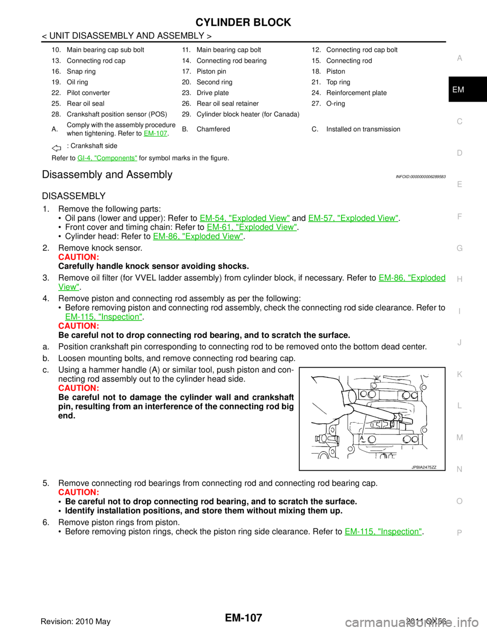
c. Using a hammer handle (A) or similar tool, push piston and con- necting rod assembly out to the cylinder head side.
CAUTION:
Be careful not to damage the cylinder wall and crankshaft
pin, resulting from an interf erence of the connecting rod big
end.
5. Remove connecting rod bearings from connecting rod and connecting rod bearing cap.
CAUTION:
Be careful not to drop connecting rod bearing, and to scratch the surface.
Identify installation positions, and store them without mixing them up.
6. Remove piston rings from piston. Before removing piston rings, check the piston ring side clearance. Refer to EM-115, "
Inspection".
10. Main bearing cap sub bolt 11. Main bearing cap bolt 12. Connecting rod cap bolt
13. Connecting rod cap 14. Connecting rod bearing 15. Connecting rod
16. Snap ring 17. Piston pin 18. Piston
19. Oil ring 20. Second ring 21. Top ring
22. Pilot converter 23. Drive plate 24. Reinforcement plate
25. Rear oil seal 26. Rear oil seal retainer 27. O-ring
28. Crankshaft position sensor (POS) 29. Cylinder block heater (for Canada)
A.Comply with the assembly procedure
when tightening. Refer to
EM-107
.B. Chamfered C. Installed on transmission
: Crankshaft side
Refer to GI-4, "
Components" for symbol marks in the figure.
JPBIA2475ZZ
Revision: 2010 May2011 QX56
Page 2673 of 5598
CYLINDER BLOCKEM-111
< UNIT DISASSEMBLY AND ASSEMBLY >
C
DE
F
G H
I
J
K L
M A
EM
NP
O
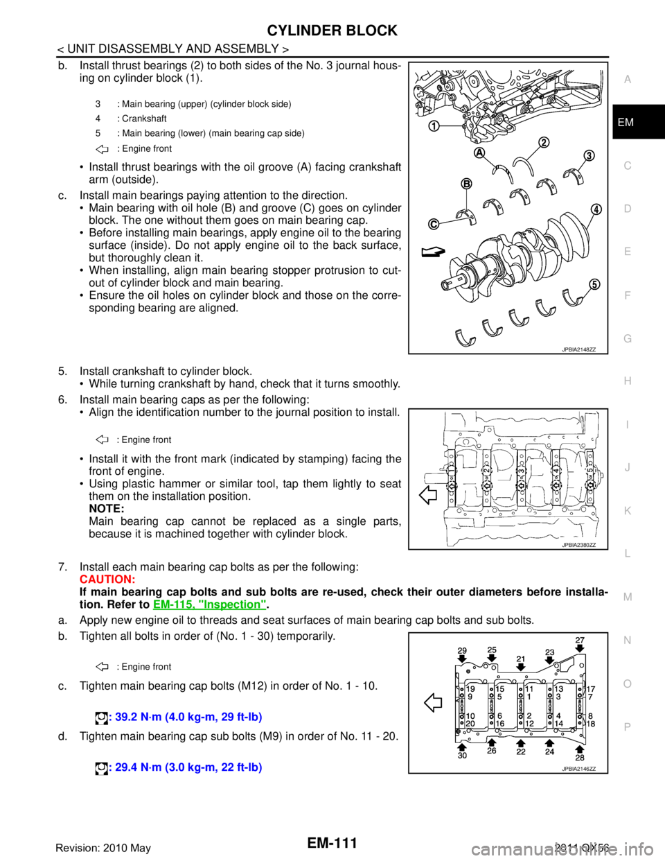
b. Install thrust bearings (2) to both sides of the No. 3 journal hous-
ing on cylinder block (1).
Install thrust bearings with the oil groove (A) facing crankshaftarm (outside).
c. Install main bearings paying attention to the direction. Main bearing with oil hole (B) and groove (C) goes on cylinderblock. The one without them goes on main bearing cap.
Before installing main bearings, apply engine oil to the bearing surface (inside). Do not apply engine oil to the back surface,
but thoroughly clean it.
When installing, align main bearing stopper protrusion to cut-
out of cylinder block and main bearing.
Ensure the oil holes on cylinder block and those on the corre-
sponding bearing are aligned.
5. Install crankshaft to cylinder block. While turning crankshaft by hand, check that it turns smoothly.
6. Install main bearing caps as per the following: Align the identification number to the journal position to install.
Install it with the front mark (indicated by stamping) facing thefront of engine.
Using plastic hammer or similar tool, tap them lightly to seat them on the installation position.
NOTE:
Main bearing cap cannot be replaced as a single parts,
because it is machined together with cylinder block.
7. Install each main bearing cap bolts as per the following: CAUTION:
If main bearing cap bolts and sub bolts are re-u sed, check their outer diameters before installa-
tion. Refer to EM-115, "
Inspection".
a. Apply new engine oil to threads and seat surfaces of main bearing cap bolts and sub bolts.
b. Tighten all bolts in order of (No. 1 - 30) temporarily.
c. Tighten main bearing cap bolts (M12) in order of No. 1 - 10.
d. Tighten main bearing cap sub bolts (M9) in order of No. 11 - 20.
3 : Main bearing (uppe r) (cylinder block side)
4 : Crankshaft
5 : Main bearing (lower) (main bearing cap side)
: Engine front
JPBIA2148ZZ
: Engine front
JPBIA2380ZZ
: Engine front
: 39.2 N·m (4.0 kg-m, 29 ft-lb)
: 29.4 N·m (3.0 kg-m, 22 ft-lb)
JPBIA2146ZZ
Revision: 2010 May2011 QX56
Page 2674 of 5598
![INFINITI QX56 2011 Factory Service Manual
EM-112
< UNIT DISASSEMBLY AND ASSEMBLY >
CYLINDER BLOCK
e. Tighten main bearing cap bolts (M12) in order of No. 1 - 10(clockwise).
CAUTION:
Use the angle wrench [SST: KV10112100 (BT8653-A)] (A) to
ch INFINITI QX56 2011 Factory Service Manual
EM-112
< UNIT DISASSEMBLY AND ASSEMBLY >
CYLINDER BLOCK
e. Tighten main bearing cap bolts (M12) in order of No. 1 - 10(clockwise).
CAUTION:
Use the angle wrench [SST: KV10112100 (BT8653-A)] (A) to
ch](/manual-img/42/57033/w960_57033-2673.png)
EM-112
< UNIT DISASSEMBLY AND ASSEMBLY >
CYLINDER BLOCK
e. Tighten main bearing cap bolts (M12) in order of No. 1 - 10(clockwise).
CAUTION:
Use the angle wrench [SST: KV10112100 (BT8653-A)] (A) to
check tightening angl e. Never make judgment by visual
inspection.
f. Tighten main bearing cap sub bolts (M9) in order of No. 11 - 20. (clockwise)
g. Tighten side bolts (M10) in order of No. 21 - 30. After installing bolts, check that crankshaft can be rotated smoothly by hand.
Check the crankshaft end play. Refer to EM-137, "
CylinderBlock".
8. Install rear oil seal retainer. Apply a continuous bead of liquid gasket with tube presser
(commercial service tool) to rear oil seal retainer as shown in
the figure.
Use Genuine RTV silicone seal ant or equivalent. Refer to
GI-22, "
Recommended Chemical Products and Sealants".
9. Install rear oil seal on rear oil seal retainer.
Apply new engine oil to both oil seal lip (A) and dust seal lip(B).
Install it so that each seal lip is oriented as shown in the figure. CAUTION:
Be careful not to scratch or make burrs on circumference
of oil seal.
Press in rear oil seal (1) to the position as shown in the figure.
Using a suitable drift [outer diameter: 101 mm (3.98 in)].
Check the garter spring is in position and seal lips are not inverted.
10. Install piston to connecting rod as per the following: Angle tightening: 40 degrees
Angle tightening: 30 degrees
JPBIA2149ZZ
: 49.0 N·m (5.0 kg-m, 36 ft-lb)
A : Protrusion
b : 4.0 - 5.6 mm (0.157 - 0.220 in)
c:
φ3.4 - 4.4 mm (0.134 - 0.173 in)
JPBIA2102ZZ
: Engine inside
: Engine outside
JPBIA0054ZZ
B : Rear oil seal retainer rear end face
a : 0 - 0.5 mm (0 - 0.020 in)
JPBIA0152ZZ
Revision: 2010 May2011 QX56
Page 2675 of 5598
CYLINDER BLOCKEM-113
< UNIT DISASSEMBLY AND ASSEMBLY >
C
DE
F
G H
I
J
K L
M A
EM
NP
O
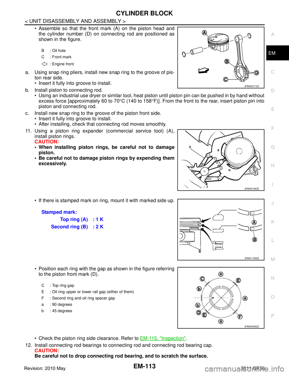
Assemble so that the front mark (A) on the piston head and
the cylinder number (D) on connecting rod are positioned as
shown in the figure.
a. Using snap ring pliers, install new snap ring to the groove of pis- ton rear side.
Insert it fully into groove to install.
b. Install piston to connecting rod. Using an industrial use dryer or similar tool, heat piston until piston pin can be pushed in by hand without
excess force [approximately 60 to 70 °C (140 to 158 °F)]. From the front to the rear, insert piston pin into
piston and connecting rod.
c. Install new snap ring to the groove of the piston front side. Insert it fully into groove to install.
After installing, check that connecting rod moves smoothly.
11. Using a piston ring expander (c ommercial service tool) (A),
install piston rings.
CAUTION:
When installing piston rings, be careful not to damage piston.
Be careful not to damage piston rings by expending them excessively.
If there is stamped mark on ri ng, mount it with marked side up.
Position each ring with the gap as shown in the figure referring to the piston front mark (D).
Check the piston ring side clearance. Refer to EM-115, "
Inspection".
12. Install connecting rod bearings to connecting rod and connecting rod bearing cap. CAUTION:
Be careful not to drop connecting r od bearing, and to scratch the surface.
B : Oil hole
C : Front mark
: Engine front
JPBIA2271ZZ
JPBIA0194ZZ
Stamped mark: To p r i n g ( A ) : 1 K
Second ring (B) : 2 K
JPBIA1720ZZ
C : Top ring gap
E : Oil ring upper or lower rail gap (either of them)
F : Second ring and oil ring spacer gap
a : 90 degrees
b : 45 degrees
JPBIA0205ZZ
Revision: 2010 May2011 QX56
Page 2677 of 5598
![INFINITI QX56 2011 Factory Service Manual
CYLINDER BLOCKEM-115
< UNIT DISASSEMBLY AND ASSEMBLY >
C
DE
F
G H
I
J
K L
M A
EM
NP
O
f. Tighten connecting rod bolts. (clockwise)
CAUTION:
Always use the angle wrench [SST: KV10112100 (B T8653-A)]. INFINITI QX56 2011 Factory Service Manual
CYLINDER BLOCKEM-115
< UNIT DISASSEMBLY AND ASSEMBLY >
C
DE
F
G H
I
J
K L
M A
EM
NP
O
f. Tighten connecting rod bolts. (clockwise)
CAUTION:
Always use the angle wrench [SST: KV10112100 (B T8653-A)].](/manual-img/42/57033/w960_57033-2676.png)
CYLINDER BLOCKEM-115
< UNIT DISASSEMBLY AND ASSEMBLY >
C
DE
F
G H
I
J
K L
M A
EM
NP
O
f. Tighten connecting rod bolts. (clockwise)
CAUTION:
Always use the angle wrench [SST: KV10112100 (B T8653-A)]. Never make judgment by visual
inspection.
After tightening connecting rod bolts, c heck that crankshaft rotates smoothly.
Check the connecting rod side clearance. Refer to EM-115, "
Inspection".
16. Install knock sensors (1). Install knock sensors in the direction shown in the figure.
After installing knock sens or, connect harness connector, and
lay it out to front of the engine.
CAUTION:
Never tighten mounting bolts while holding connector.
If any impact by dropping is applied to knock sensor,
replace it with new one.
NOTE:
Check that there is no foreign material on the cylinder block
mating surface and the back surface of knock sensor.
Check that knock sensor does not interfere with other parts.
17. Install oil filter (for VVEL ladder assembly).
18. Install drive plate. Install drive plate (4) and reinforcement plate (3) as shown inthe figure.
When installing drive plate to crankshaft (1), be sure to cor- rectly align crankshaft side dowel pin and drive plate side
dowel pin hole.
CAUTION:
If these are not aligned correct ly, engine runs roughly and
“MIL” illuminates.
Holding ring gear with the ring gear stopper [SST: KV10119200 (J-49277)].
Tighten the mounting bolts crosswise over several times.
19. Assemble in the reverse order of disassembly.
InspectionINFOID:0000000006289584
CRANKSHAFT END PLAY
Measure the clearance between thrust bearings and crankshaft arm when crankshaft is moved fully forward or backward with a dial
indicator (A).
If the measured value exceeds t he limit, replace thrust bearings,
and measure again. If it still exceeds the limit, replace crankshaft
also. : 19.6 N·m (2.0 kg-m, 14.5 ft-lb)
Angle tightening: 90 degrees
: Engine front
2 : Pilot converter
A : Rounded : Engine front
JPBIA4515ZZ
JPBIA2275ZZ
Standard and limit : Refer to EM-137, "CylinderBlock".
JPBIA2477ZZ
Revision: 2010 May2011 QX56
Page 2679 of 5598
CYLINDER BLOCKEM-117
< UNIT DISASSEMBLY AND ASSEMBLY >
C
DE
F
G H
I
J
K L
M A
EM
NP
O
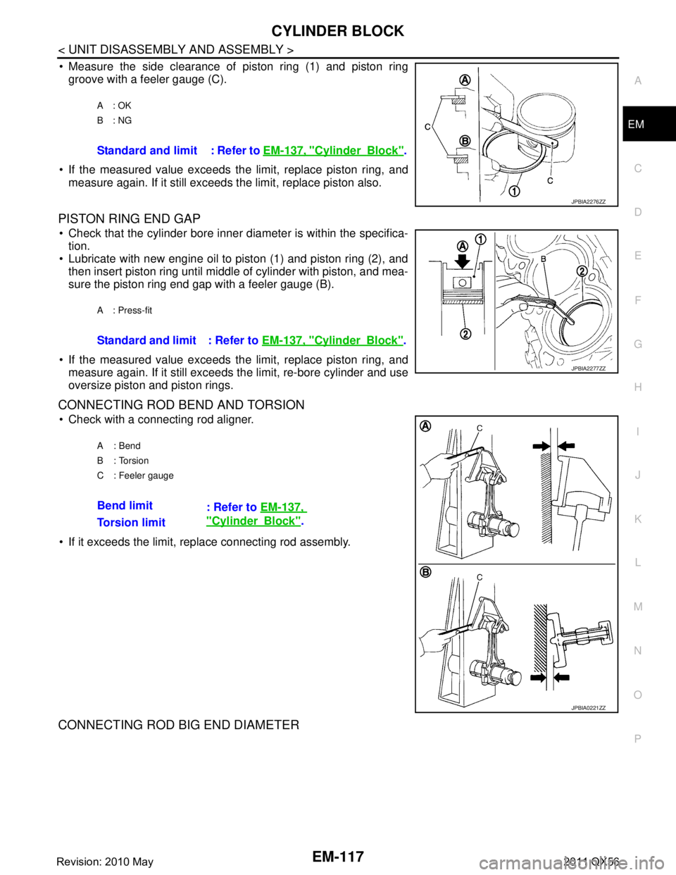
Measure the side clearance of piston ring (1) and piston ring
groove with a feeler gauge (C).
If the measured value exceeds t he limit, replace piston ring, and
measure again. If it still exceeds the limit, replace piston also.
PISTON RING END GAP
Check that the cylinder bore inner diameter is within the specifica- tion.
Lubricate with new engine oil to piston (1) and piston ring (2), and
then insert piston ring until middle of cylinder with piston, and mea-
sure the piston ring end gap with a feeler gauge (B).
If the measured value exceeds t he limit, replace piston ring, and
measure again. If it still exceeds the limit, re-bore cylinder and use
oversize piston and piston rings.
CONNECTING ROD BEND AND TORSION
Check with a connecting rod aligner.
If it exceeds the limit, replace connecting rod assembly.
CONNECTING ROD BIG END DIAMETER
A: OK
B: NG
Standard and limit : Refer to EM-137, "CylinderBlock".
JPBIA2276ZZ
A : Press-fit
Standard and limit : Refer to EM-137, "CylinderBlock".
JPBIA2277ZZ
A: Bend
B: Torsion
C : Feeler gauge
Bend limit
: Refer to EM-137,
"CylinderBlock".
Torsion limit
JPBIA0221ZZ
Revision: 2010 May2011 QX56
Page 2686 of 5598
EM-124
< UNIT DISASSEMBLY AND ASSEMBLY >
CYLINDER BLOCK
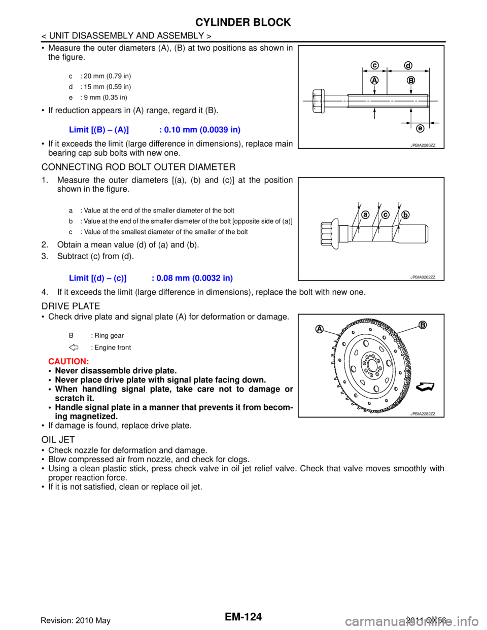
Measure the outer diameters (A), (B) at two positions as shown in
the figure.
If reduction appears in (A) range, regard it (B).
If it exceeds the limit (large difference in dimensions), replace main bearing cap sub bolts with new one.
CONNECTING ROD BOLT OUTER DIAMETER
1. Measure the outer diameters [(a), (b) and (c)] at the position shown in the figure.
2. Obtain a mean value (d) of (a) and (b).
3. Subtract (c) from (d).
4. If it exceeds the limit (large difference in dimensions), replace the bolt with new one.
DRIVE PLATE
Check drive plate and signal plate (A) for deformation or damage.
CAUTION:
Never disassemble drive plate.
Never place drive plate with signal plate facing down.
When handling signal plate, take care not to damage or scratch it.
Handle signal plate in a manner that prevents it from becom-
ing magnetized.
If damage is found, replace drive plate.
OIL JET
Check nozzle for deformation and damage.
Blow compressed air from nozzle, and check for clogs.
Using a clean plastic stick, press check valve in oil je t relief valve. Check that valve moves smoothly with
proper reaction force.
If it is not satisfied, clean or replace oil jet.
c : 20 mm (0.79 in)
d : 15 mm (0.59 in)
e : 9 mm (0.35 in)
Limit [(B) – (A)] : 0.10 mm (0.0039 in)
JPBIA2280ZZ
a : Value at the end of the smaller diameter of the bolt
b : Value at the end of the smaller diameter of the bolt [opposite side of (a)]
c : Value of the smallest diameter of the smaller of the bolt
Limit [(d) – (c)] : 0.08 mm (0.0032 in)JPBIA0262ZZ
B : Ring gear
: Engine front
JPBIA2282ZZ
Revision: 2010 May2011 QX56