2011 INFINITI QX56 check oil
[x] Cancel search: check oilPage 3066 of 5598
HA-10
< PREPARATION >
PREPARATION
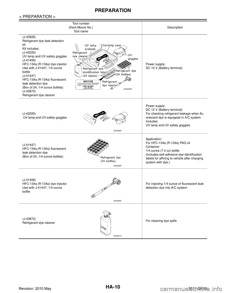
(J-43926)
Refrigerant dye leak detection
kit
Kit includes:
(J-42220)
UV lamp and UV safety goggles
(J-41459)
HFC-134a (R-134a) dye injector
Use with J-41447, 1/4 ounce
bottle
(J-41447)
HFC-134a (R-134a) fluorescent
leak detection dye
(Box of 24, 1/4 ounce bottles)
(J-43872)
Refrigerant dye cleanerPower supply:
DC 12 V (Battery terminal)
(J-42220)
UV lamp and UV safety goggles Power supply:
DC 12 V (Battery terminal)
For checking refrigerant leakage when flu-
orescent dye is equipped in A/C system
Includes:
UV lamp and UV safety goggles
(J-41447)
HFC-134a (R-134a) fluorescent
leak detection dye
(Box of 24, 1/4 ounce bottles) Application:
For HFC-134a (R-134a) PAG oil
Container:
1/4 ounce (7.4 cc) bottle
(Includes self-adhesive dye identification
labels for affixing to vehicle after charging
system with dye.)
(J-41459)
HFC-134a (R-134a) dye injector
Use with J-41447, 1/4 ounce
bottle For injecting 1/4 ounce of fluorescent leak
detection dye into A/C system
(J-43872)
Refrigerant dye cleaner For cleaning dye spills
Tool number
(Kent-Moore No.)
Tool name Description
ZHA200H
SHA438F
SHA439F
SHA440F
SHA441F
Revision: 2010 May2011 QX56
Page 3068 of 5598

HA-12
< PREPARATION >
PREPARATION
Commercial Service Tool
INFOID:0000000006276518
Sealant or/and LubricantINFOID:0000000006276143
HFC-134a (R-134a) Service Tool and Equipment
Never mix HFC-134a (R-134a) refrigerant and/or its s pecified lubricant with CFC-12 (R-12) refrigerant and/
or its lubricant.
Separate and non-interchangeable service equipment must be used for handling each type of refrigerant/ lubricant.
Refrigerant container fittings, service hose fittings and service equipment fittings (equipment which handles
refrigerant and/or lubricant) are different between CF C-12 (R-12) and HFC-134a (R-134a). This is to avoid
mixed use of the refrigerants/lubricant.
Never use adapters that convert one size fitting to another: refrigerant/lubricant contamination occurs and
compressor malfunction may result.
Tool name Description
Refrigerant identifier equipment Checking for refrigerant purity and
system contamination
Power tools For loosening bolts and nuts
RJIA0197E
PBIC0190E
Tool name Description
HFC-134a (R-134a) refrigerant Container color: Light blue
Container marking: HFC-134a (R-
134a)
Fitting size: Thread size
Large container 1/2
″-16 ACME
A/C System Oil Type S (DH-PS) Type: Polyalkylene glycol oil (PAG),
type S (DH-PS)
Application:
HFC-134a (R-134a) swash plate com-
pressors
Capacity: 40 m (1.4 Imp fl oz.)
S-NT196
S-NT197
Revision: 2010 May2011 QX56
Page 3078 of 5598
HA-22
< BASIC INSPECTION >
LUBRICANT
LUBRICANT
DescriptionINFOID:0000000006276153
MAINTENANCE OF LUBRICANT LEVEL
The compressor lubricant is circulating in the system together with the refrigerant. It is necessary to fill com-
pressor with lubricant when replacing A/C system pa rts or when a large amount of refrigerant leakage is
detected. It is important to always maintain lubricant level within the specified level. Otherwise, the following
conditions may occur.
Insufficient lubricant amount: Stuck compressor
Excessive lubricant amount: Insufficient cooling (caused by insufficient heat exchange)
InspectionINFOID:0000000006276154
If a compressor is malfunctioning (internal noise, insufficient cooling), check the compressor oil.
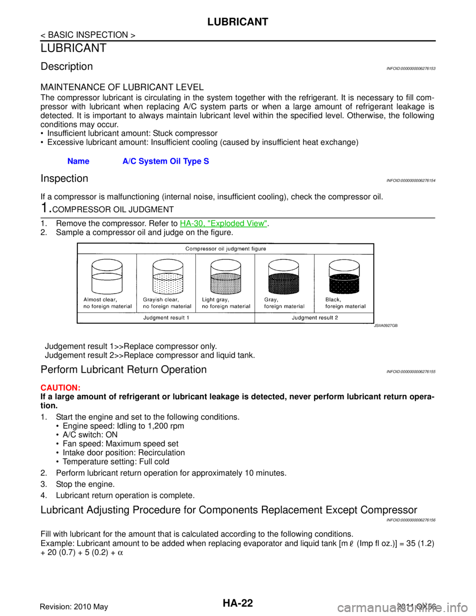
1.COMPRESSOR OIL JUDGMENT
1. Remove the compressor. Refer to HA-30, "
Exploded View".
2. Sample a compressor oil and judge on the figure.
Judgement result 1>>Replace compressor only.
Judgement result 2>>Replace compressor and liquid tank.
Perform Lubricant Return OperationINFOID:0000000006276155
CAUTION:
If a large amount of refrigerant or lubricant leakag e is detected, never perform lubricant return opera-
tion.
1. Start the engine and set to the following conditions.
Engine speed: Idling to 1,200 rpm
A/C switch: ON
Fan speed: Maximum speed set
Intake door position: Recirculation
Temperature setting: Full cold
2. Perform lubricant return operation for approximately 10 minutes.
3. Stop the engine.
4. Lubricant return operation is complete.
Lubricant Adjusting Procedure for Comp onents Replacement Except Compressor
INFOID:0000000006276156
Fill with lubricant for the amount that is calculated according to the following conditions.
Example: Lubricant amount to be added when replacing evapor ator and liquid tank [m (Imp fl oz.)] = 35 (1.2)
+ 20 (0.7) + 5 (0.2) + α
Name A/C System Oil Type S
JSIIA0927GB
Revision: 2010 May2011 QX56
Page 3085 of 5598
NOISEHA-29
< SYMPTOM DIAGNOSIS >
C
DE
F
G H
J
K L
M A
B
HA
N
O P
NOISE
Symptom TableINFOID:0000000006276161
Symptom Noise source Probable cause Corrective action
Unusual noise from compressor
when A/C is ON. Inside of compressor
Wear, breakage, or clogging of foreign
material in inner parts. Check compressor oil. Re-
fer to
HA-22, "
Inspection".
Magnet clutch Contact of clutch disc with pulley. Check clearance between
clutch disc and pulley. Refer
to
HA-32, "
Inspection".
Compressor body Loosened compressor mounting bolts. Check bolts for tightness.
Refer to
HA-30, "
Exploded
View".
Unusual noise from cooler piping. Cooler piping (pipe and
flexible hose)Improper installation of clip and brack-
et. Check the installation condi-
tion of the cooler piping. Re-
fer to
HA-33, "
Exploded
View".
Unusual noise from expansion
valve when A/C is ON. Expansion valveShortage of refrigerant. Check for leakage.
Collect all refrigerant,
evacuate refrigerant cycle
again, and then refill it
with the specified amount
of refrigerant.
Wear, breakage, or clogging of foreign
material in inner parts. Eliminate foreign material
from expansion valve, or re-
place it.
Unusual noise from belt. — Loosened belt
Check belt tension. Refer to
EM-20, "
Checking".
Internal compressor parts ge t locked Replace compressor.
Revision: 2010 May2011 QX56
Page 3087 of 5598
COMPRESSORHA-31
< REMOVAL AND INSTALLATION >
C
DE
F
G H
J
K L
M A
B
HA
N
O P
Perform lubricant return operati on before each refrigeration system disassembly. However, if a large
amount of refrigerant or lubricant is detected, n ever perform lubricant return operation. Refer to HA-
22, "Perform Lubricant Return Operation".
REMOVAL
1. Use a refrigerant collecting equipment (for HF C-134a) to discharge the refrigerant. Refer to HA-20, "Recy-
cle Refrigerant".
2. Remove air cleaner. Refer to EM-27, "
Removal and Installation".
3. Remove mounting bolts, and then disconnect low-pressure flexible hose and high-pressure flexible hose from the compressor.
CAUTION:
Cap or wrap the joint of the A/C piping and comp ressor with suitable material such as vinyl tape to
avoid the entry of air.
4. Remove front under cover. Refer to EXT-25, "
Exploded View".
5. Remove drive belt. Refer to EM-20, "
Removal and Installation".
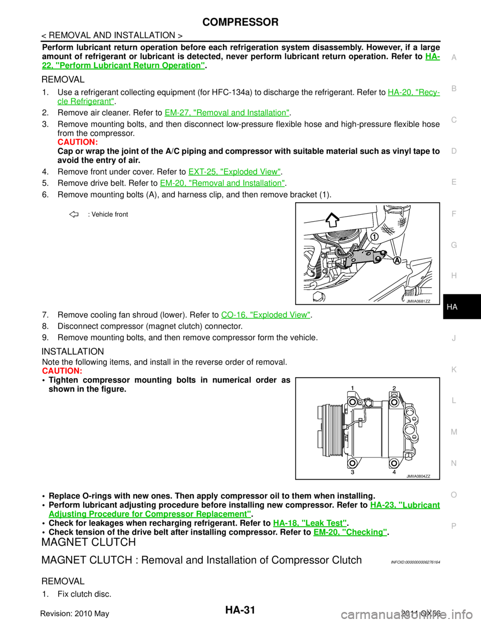
6. Remove mounting bolts (A), and harness clip, and then remove bracket (1).
7. Remove cooling fan shroud (lower). Refer to CO-16, "
Exploded View".
8. Disconnect compressor (magnet clutch) connector.
9. Remove mounting bolts, and then remove compressor form the vehicle.
INSTALLATION
Note the following items, and install in the reverse order of removal.
CAUTION:
Tighten compressor mounting bolts in numerical order as shown in the figure.
Replace O-rings with new ones. Then apply compressor oil to them when installing.
Perform lubricant adjusting procedure befo re installing new compressor. Refer to HA-23, "
Lubricant
Adjusting Procedure for Compressor Replacement".
Check for leakages when recharging refrigerant. Refer to HA-18, "
Leak Test".
Check tension of the drive belt afte r installing compressor. Refer to EM-20, "
Checking".
MAGNET CLUTCH
MAGNET CLUTCH : Removal and Inst allation of Compressor ClutchINFOID:0000000006276164
REMOVAL
1. Fix clutch disc.
: Vehicle front
JMIIA0681ZZ
JMIIA0804ZZ
Revision: 2010 May2011 QX56
Page 3088 of 5598
HA-32
< REMOVAL AND INSTALLATION >
COMPRESSOR
2. Remove center bolt, and then remove clutch disc.
3. Remove snap ring using external snap ring pliers.
4. Position center pulley puller on the end of the drive shaft, and remove pulley assembly using any commer-
cially available pulley puller.
To prevent pulley groove from being deformed, pulle r claws should be positioned into the edge of the pul-
ley assembly.
5. Disconnect field coil harness from compressor unit.
6. Remove screws, and then remove field coil.
INSTALLATION
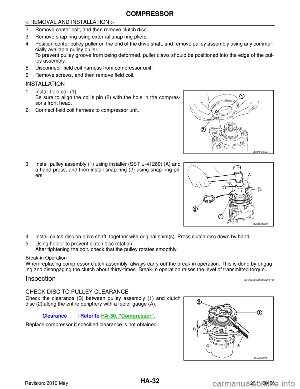
1. Install field coil (1). Be sure to align the coil’s pin (2) with the hole in the compres-
sor’s front head.
2. Connect field coil harness to compressor unit.
3. Install pulley assembly (1) using installer (SST: J-41260) (A) and a hand press, and then install snap ring (2) using snap ring pli-
ers.
4. Install clutch disc on drive shaft, together with original shim(s). Press clutch disc down by hand.
5. Using holder to prevent clutch disc rotation. After tightening the bolt, check that the pulley rotates smoothly.
Break-in Operation
When replacing compressor clutch assembly, always carry out the break-in operation. This is done by engag-
ing and disengaging the clutch about thirty-times. Break-i n operation raises the level of transmitted torque.
InspectionINFOID:0000000006276165
CHECK DISC TO PULLEY CLEARANCE
Check the clearance (B) between pulley assembly (1) and clutch
disc (2) along the entire periphery with a feeler gauge (A).
Replace compressor if specified clearance is not obtained.
JMIIA0575ZZ
JMIIA0576ZZ
Clearance : Refer to HA-50, "Compressor".
JPIIA1566ZZ
Revision: 2010 May2011 QX56
Page 3091 of 5598
COOLER PIPE AND HOSEHA-35
< REMOVAL AND INSTALLATION >
C
DE
F
G H
J
K L
M A
B
HA
N
O P
Check for leakages when recharging refrigerant. Refer to HA-18, "Leak Test".
LOW-PRESSURE FLEXIBLE HOSE
LOW-PRESSURE FLEXIBLE HOSE : Removal and InstallationINFOID:0000000006276174
CAUTION:
Perform lubricant return operation before each refrigeration system disassembly. However, if a large
amount of refrigerant or lubricant is detected, n ever perform lubricant return operation. Refer to HA-
22, "Perform Lubricant Return Operation".
REMOVAL
1. Use a refrigerant collecting equipment (for HF C-B4a) to discharge the refrigerant. Refer to HA-22, "Per-
form Lubricant Return Operation".
2. Remove air cleaner. Refer to EM-27, "
Removal and Installation".
3. Remove the mounting bolt installed in low-pressure flexible hose from the vehicle.
4. Remove mounting bolts, and then remove low-pressure flexible hose from the vehicle. CAUTION:
Cap or wrap the joint of the A/C piping and comp ressor with suitable material such as vinyl tape to
avoid the entry of air.
INSTALLATION
Note the following items, and install in the reverse order of removal.
CAUTION:
Replace O-rings with new ones. Then apply compressor oil to them when installing.
Check for leakages when recharging refrigerant. Refer to HA-18, "
Leak Test".
HIGH-PRESSURE PIPE
HIGH-PRESSURE PIPE : Removal and InstallationINFOID:0000000006276175
CAUTION:
Perform lubricant return operati on before each refrigeration system disassembly. However, if a large
amount of refrigerant or lubricant is detected, n ever perform lubricant return operation. Refer to HA-
22, "Perform Lubricant Return Operation".
REMOVAL
1. Use a refrigerant collecting equipment (for HF C-134a) to discharge the refrigerant. Refer to HA-22, "Per-
form Lubricant Return Operation".
2. Remove low-pressure pipe. Refer to HA-36, "
LOW-PRESSURE PIPE : Removal and Installation".
3. Remove battery. Refer to PG-164, "
Removal and Installation".
4. Remove mounting bolts, and then remove battery bracket.
5. Disconnect harness connector, harness clip and ground harness for securing work space.
6. Remove mounting bolt, and then disconnec t high-pressure pipe from condenser.
CAUTION:
Cap or wrap the joint of the A/C piping and comp ressor with suitable material such as vinyl tape to
avoid the entry of air.
7. Remove high-pressure pipe mounting nut.
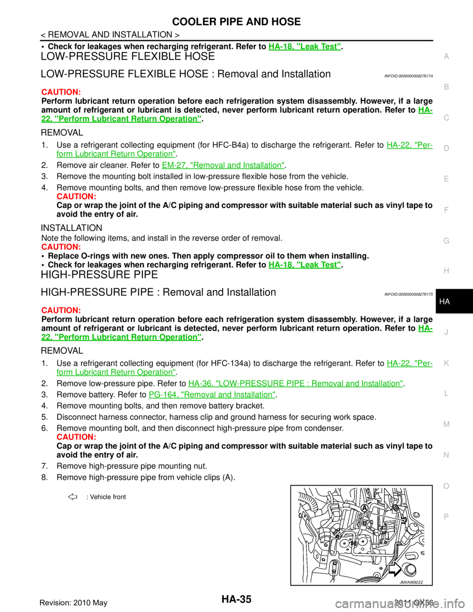
8. Remove high-pressure pipe from vehicle clips (A).
: Vehicle front
JMIIA0682ZZ
Revision: 2010 May2011 QX56
Page 3092 of 5598
HA-36
< REMOVAL AND INSTALLATION >
COOLER PIPE AND HOSE
9. Partly remove rear half of front fender protector RH. Refer to EXT-23, "FENDER PROTECTOR : Exploded
View".
10. Remove high-pressure pipe.
INSTALLATION
Note the following items, and install in the reverse order of removal.
CAUTION:
Replace O-rings with new ones. Then apply compressor oil to them when installing.
Check for leakages when recharging refrigerant. Refer to HA-18, "
Leak Test".
LOW-PRESSURE PIPE
LOW-PRESSURE PIPE : Removal and InstallationINFOID:0000000006276176
CAUTION:
Perform lubricant return operation before each re frigeration system disassembly. However, if a large
amount of refrigerant or lubrican t is detected, never perform lubricant return operation. Refer to HA-
22, "Perform Lubricant Return Operation".
REMOVAL
1. Use a refrigerant collecting equipment (for HF C-134a) to discharge the refrigerant. Refer to HA-22, "Per-
form Lubricant Return Operation".
2. Drain engine coolant from cooling system. Refer to CO-8, "
Draining".
3. Remove engine cover. Refer to EM-25, "
Removal and Installation".
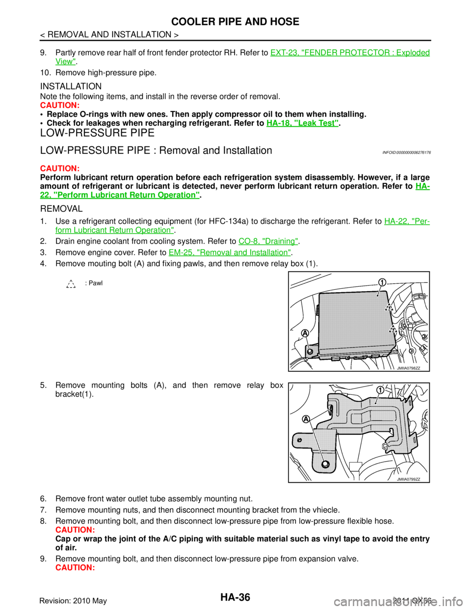
4. Remove mouting bolt (A) and fixing pawls, and then remove relay box (1).
5. Remove mounting bolts (A), and then remove relay box bracket(1).
6. Remove front water outlet tube assembly mounting nut.
7. Remove mounting nuts, and then disconnec t mounting bracket from the vhiecle.
8. Remove mounting bolt, and then disconnect low-pressure pipe from low-pressure flexible hose. CAUTION:
Cap or wrap the joint of the A/C piping with suitab le material such as vinyl tape to avoid the entry
of air.
9. Remove mounting bolt, and then disconnect low-pressure pipe from expansion valve. CAUTION:
: Pawl
JMIIA0798ZZ
JMIIA0799ZZ
Revision: 2010 May2011 QX56