Page 3254 of 5598
![INFINITI QX56 2011 Factory Service Manual
HAC-148
< REMOVAL AND INSTALLATION >[AUTOMATIC AIR CONDITIONING]
IN-VEHICLE SENSOR
IN-VEHICLE SENSOR
FRONT A/C UNIT ASSEMBLY
FRONT A/C UNIT ASSEMBLY :
Removal and InstallationINFOID:0000000006276001 INFINITI QX56 2011 Factory Service Manual
HAC-148
< REMOVAL AND INSTALLATION >[AUTOMATIC AIR CONDITIONING]
IN-VEHICLE SENSOR
IN-VEHICLE SENSOR
FRONT A/C UNIT ASSEMBLY
FRONT A/C UNIT ASSEMBLY :
Removal and InstallationINFOID:0000000006276001](/manual-img/42/57033/w960_57033-3253.png)
HAC-148
< REMOVAL AND INSTALLATION >[AUTOMATIC AIR CONDITIONING]
IN-VEHICLE SENSOR
IN-VEHICLE SENSOR
FRONT A/C UNIT ASSEMBLY
FRONT A/C UNIT ASSEMBLY :
Removal and InstallationINFOID:0000000006276001
REMOVAL
1. Remove instrument lower panel LH. Refer to IP-14, "Removal and Installation".
2. Remove fixing screw, and then remove in-vehicle sensor.
INSTALLATION
Install in the reverse order of removal.
REAR A/C UNIT ASSEMBLY
REAR A/C UNIT ASSEMBLY : Removal and InstallationINFOID:0000000006276002
REMOVAL
1. Remove rear A/C unit assembly. Refer to HA-47, "REAR A/C UNIT ASSEMBLY : Removal and Installa-
tion".
2. Remove the intake sensor from rear A/C unit assembly.
INSTALLATION
Note the following items, and install in the reverse order of removal.
CAUTION:
Replace O-rings with new ones. Then apply the compressor oil to them when installing.
Mark the mounting position of intake sensor bracket prior to removal so that the reinstalled sensor
can be located in the same position.
Never rotate the bracket insertion part when removing and installing the intake sensor.
Check for leakages when recharging refrigerant. Refer to HA-18, "
Leak Test".
Revision: 2010 May2011 QX56
Page 3256 of 5598
HAC-150
< REMOVAL AND INSTALLATION >[AUTOMATIC AIR CONDITIONING]
INTAKE SENSOR
INTAKE SENSOR
Exploded ViewINFOID:0000000006276004
Refer to
HA-41, "Exploded View".
Removal and InstallationINFOID:0000000006276005
REMOVAL
1. Remove the front evaporator assembly. Refer to HA-43, "EVAPORATOR : Removal and Installation".
2. Remove the intake sensor from front evaporator.
INSTALLATION
Note the following items, and install in the reverse order of removal.
CAUTION:
Replace O-rings with new ones. Then apply the compressor oil to them when installing.
Mark the mounting position of intake sensor bracket prior to removal so that the reinstalled sensor
can be located in the same position.
Never rotate the bracket insertion part when removing and installing the intake sensor.
Check for leakages when recharging refrigerant. Refer to HA-18, "
Leak Test".
Revision: 2010 May2011 QX56
Page 3393 of 5598

PRECAUTIONSIP-3
< PRECAUTION >
C
DE
F
G H
I
K L
M A
B
IP
N
O P
5. When the repair work is completed, re-connect both battery cables. With the brake pedal released, turn
the push-button ignition switch from ACC position to ON position, then to LOCK position. (The steering
wheel will lock when the push-button ignition switch is turned to LOCK position.)
6. Perform self-diagnosis check of a ll control units using CONSULT-III.
ServiceINFOID:0000000006113090
Disconnect battery negative terminal in advance.
Disconnect air bag system line in advance.
Never tamper with or force air bag lid open, as this may adversely affect air bag performance.
Be careful not to scratch pad and other parts.
When removing or disassembling any part, be careful not to damage or deform it. Protect parts, that may get
in the way with a shop cloth.
When removing parts with a screwdriver or other tool, cover the tool surface with vinyl tape to protect parts.
Keep removed parts protected with a shop cloth.
If a clip is deformed or damaged, replace it.
If an unreusable part is removed, replace it with a new one.
Tighten bolts and nuts firmly to the specified torque.
After reassembly is complete, check that each part functions correctly.
Remove stains via the following procedure.
Water-soluble stains:
Dip a soft cloth in warm water, and then squeeze it tightly. After wiping off the stain, wipe with a soft dry cloth.
Oil stain:
Dissolve a synthetic detergent in warm water (density of 2 to 3%), dip the cloth, then wipe off the stain with the
cloth. Next, dip the cloth in fresh water and squeeze it tightly. Then wipe off the detergent completely. Then
wipe the area with a soft dry cloth.
Never use any organic solvent, such as thinner or benzine.
Revision: 2010 May2011 QX56
Page 3660 of 5598

ENGINE OILLU-7
< PERIODIC MAINTENANCE >
C
DE
F
G H
I
J
K L
M A
LU
NP
O
PERIODIC MAINTENANCE
ENGINE OIL
InspectionINFOID:0000000006289616
OIL LEVEL
NOTE:
Before starting engine, put vehicle horizontally and check
the engine oil level. If engine is already started, stop
it and allow 10 minutes before checking.
1. Pull out oil level gauge and wipe it clean.
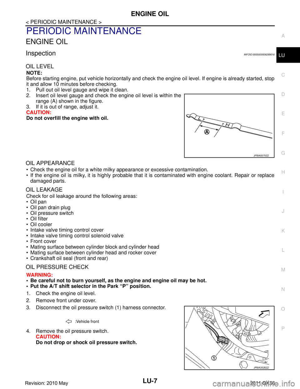
2. Insert oil level gauge and check the engine oil level is within the range (A) shown in the figure.
3. If it is out of range, adjust it.
CAUTION:
Do not overfill the engine with oil.
OIL APPEARANCE
Check the engine oil for a white milky appearance or excessive contamination.
If the engine oil is milky, it is highly probable that it is contaminated with engine coolant. Repair or replace
damaged parts.
OIL LEAKAGE
Check for oil leakage around the following areas:
Oil pan
Oil pan drain plug
Oil pressure switch
Oil filter
Oil cooler
Intake valve timing control cover
Intake valve timing control solenoid valve
Front cover
Mating surface between cylinder block and cylinder head
Mating surface between cylinder head and rocker cover
Crankshaft oil seal (front and rear)
OIL PRESSURE CHECK
WARNING:
• Be careful not to burn yourself, as th e engine and engine oil may be hot.
Put the A/T shift selector in the Park “P” position.
1. Check the engine oil level.
2. Remove front under cover.
3. Disconnect the oil pressure switch (1) harness connector.
4. Remove the oil pressure switch. CAUTION:
Do not drop or shock oil pressure switch.
JPBIA0070ZZ
:Vehicle front
JPBIA3526ZZ
Revision: 2010 May2011 QX56
Page 3661 of 5598
![INFINITI QX56 2011 Factory Service Manual
LU-8
< PERIODIC MAINTENANCE >
ENGINE OIL
5. Install the oil pressure gauge [SST: ST25051001 (J25695-1)] (A)and hose [SST: ST25052000 (J25695-2)] (B).
6. Start the engine and warm it up to normal oper INFINITI QX56 2011 Factory Service Manual
LU-8
< PERIODIC MAINTENANCE >
ENGINE OIL
5. Install the oil pressure gauge [SST: ST25051001 (J25695-1)] (A)and hose [SST: ST25052000 (J25695-2)] (B).
6. Start the engine and warm it up to normal oper](/manual-img/42/57033/w960_57033-3660.png)
LU-8
< PERIODIC MAINTENANCE >
ENGINE OIL
5. Install the oil pressure gauge [SST: ST25051001 (J25695-1)] (A)and hose [SST: ST25052000 (J25695-2)] (B).
6. Start the engine and warm it up to normal operating temperature.
7. Check the engine oil pressure with engine running under no-load. Refer to LU-17, "
EngineOilPressure".
CAUTION:
If the difference is extreme, check the oil passages and oil pump for leaks and blockages.
8. After the inspections, install oil pressure switch as follows:
a. Remove old liquid gasket adhering to oil pressure switch and engine.
b. Apply liquid gasket and tighten oil pressure switch to the specification. Use Genuine RTV Silicone Seal ant or equivalent. Refer to GI-22, "
Recommended Chemical Prod-
ucts and Sealants".
c. After warming up engine, make sure there is no leakage of engine oil with engine running.
DrainingINFOID:0000000006289617
WARNING:
Be careful not to burn yourself, as th e engine and engine oil may be hot.
Prolonged and repeated contact with used engine oil may cause skin cancer; try to avoid direct skin
contact with used oil. If skin contact is made, wash thoroughly with soap or hand cleaner as soon as
possible.
1. Warm up the engine, and check for any oil leaks.
2. Stop the engine and wait for at least 10 minutes.
3. Remove drain plug and oil filler cap to drain the old oil.
RefillingINFOID:0000000006289618
1. Install drain plug with new washer. CAUTION:
Be sure to clean drain plug and install with new washer.
2. Refill with new engine oil. Engine oil specification and viscosity:
Refer to MA-10, "
Fluids and Lubricants".
CAUTION:
The refill capacity depends on the engine oi l temperature and drain time. Use these specifica-
tions for reference only.
Always use oil level gauge to determine the proper amount of engine oil in engine.
3. Warm up the engine and check area around drain plug and oil filter for engine oil leakage.
4. Stop the engine and wait for 10 minutes.
5. Check the engine oil level. Refer to LU-7, "
Inspection".
JPBIA0074ZZ
Oil pressure switch torque : Refer to EM-57, "Exploded View".
Tightening torque : Refer to EM-54, "
Exploded View".
Engine oil capacity : Refer to LU-17, "
Periodical Maintenance Specification".
Revision: 2010 May2011 QX56
Page 3662 of 5598

OIL FILTERLU-9
< PERIODIC MAINTENANCE >
C
DE
F
G H
I
J
K L
M A
LU
NP
O
OIL FILTER
Removal and InstallationINFOID:0000000006289619
REMOVAL
1. Remove front under cover.
2. Drain engine oil. Refer to
LU-8, "
Draining".
3. Remove oil filter using oil filter wrench [SST: KV10115801 (J- 38956)].
WARNING:
Be careful not to burn yourself, as the engine and engine oil
may be hot.
CAUTION:
The oil filter is equipped with a pressure relief valve.
Use Genuine NISSAN oil filter or equivalent.
When removing, prepare a s hop cloth to absorb any
engine oil leaks or spills.
Do not allow engine oil to adhere to the drive belts.
Completely wipe off any engine oil that adheres to the engine and the vehicle.
INSTALLATION
1. Remove foreign materials adhering to the oil filter seal mating surface.
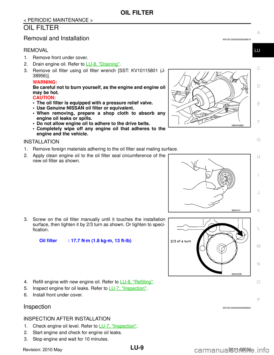
2. Apply clean engine oil to the oil filter seal circumference of the
new oil filter as shown.
3. Screw on the oil filter manually until it touches the installation surface, then tighten it by 2/3 turn as shown. Or tighten to speci-
fication.
4. Refill engine with new engine oil. Refer to LU-8, "
Refilling".
5. Inspect engine for oil leaks. Refer to LU-7, "
Inspection".
6. Install front under cover.
InspectionINFOID:0000000006289620
INSPECTION AFTER INSTALLATION
1. Check engine oil level. Refer to LU-7, "Inspection".
2. Start engine and check for engine oil leaks.
3. Stop engine and wait for 10 minutes.
WBIA0388E
SMA010
Oil filter : 17.7 N·m (1.8 kg-m, 13 ft-lb)
SMA229B
Revision: 2010 May2011 QX56
Page 3663 of 5598
LU-10
< PERIODIC MAINTENANCE >
OIL FILTER
4. Check engine oil level and add engine oil as required.
Revision: 2010 May2011 QX56
Page 3665 of 5598

LU-12
< REMOVAL AND INSTALLATION >
OIL COOLER
CAUTION:
Perform this step when engine is cold.
4. Remove oil filter. Refer to LU-9, "
Removal and Installation".
5. Remove connector bolt, and remove oil cooler.
INSTALLATION
Installation is in the reverse order of removal, paying attention to the following:
Confirm that no foreign objects are adhering to the sealing surfaces of the oil cooler and oil pan.
InspectionINFOID:0000000006289623
INSPECTION AFTER REMOVAL
Oil Cooler
Check oil cooler for cracks. Check oil cooler for clogging by blowing compressed air through engine coolant
inlet. If necessary, replace oil cooler assembly.
Relief Valve
Inspect relief valve for movement, cracks and breaks by pushing the ball. If replacement is necessary, remove
the valve by prying it out using a suitable tool. Install a new valve in place by tapping it in.
INSPECTION AFTER INSTALLATION
1. Check engine oil and engine coolant levels and add engine oil and engine coolant. Refer to LU-7, "Inspec-
tion" and CO-8, "Inspection".
2. Start the engine, and check for l eaks of engine oil or engine coolant.
3. Stop the engine and wait for 10 minutes.
4. Check the engine oil level and engine coolant level again. Refer to LU-7, "
Inspection" and CO-8, "Inspec-
tion"
Revision: 2010 May2011 QX56