2011 INFINITI QX56 check oil
[x] Cancel search: check oilPage 3779 of 5598

MWI-36
< ECU DIAGNOSIS INFORMATION >
COMBINATION METER
LIGHT INDIgnition switch
ONTail lamp indicator lamp ON On
Tail lamp indicator lamp OFF Off
OIL W/L Ignition switch
ONOil pressure warning lamp ON On
Oil pressure warning lamp OFF Off
MIL Ignition switch
ONMalfunction indicator lamp ON On
Malfunction indicator lamp OFF Off
GLOW IND Ignition switch
ONNOTE:
This item is displayed, but cannot be moni-
tored.
Off
CRUISE IND Ignition switch
ONCRUISE indicator ON On
CRUISE indicator OFF Off
SET IND Ignition switch
ONSET indicator ON On
SET indicator OFF Off
CRUISE W/L Ignition switch
ONCRUISE warning lamp ON On
CRUISE warning lamp OFF Off
BA W/L Ignition switch
ONIBA OFF indicator lamp ON On
IBA OFF indicator lamp OFF Off
ATC/T-AMT W/L Ignition switch
ONA/T check warning lamp ON On
A/T check warning lamp OFF Off
ATF TEMP W/L Ignition switch
ONNOTE:
This item is displayed, but cannot be moni-
tored.
Off
4WD W/L Ignition switch
ON4WD warning lamp ON On
4WD warning lamp OFF Off
FUEL W/L Ignition switch
ONDuring low fuel warning indication On
Other than the above Off
WASHER W/L Ignition switch
ONDuring low washer flui
d warning indication On
Other than the above Off
AIR PRES W/L Ignition switch
ONLow tire pressure
warning lamp ON On
Low tire pressure warning lamp OFF Off
KEY G/Y W/L Ignition switch
ONKEY warning lamp (Green/Yellow) ON On
KEY warning lamp (Green/Yellow) OFF Off
KEY KNOB W/L Ignition switch
ONNOTE:
This item is displayed, but cannot be moni-
tored.
Off
AFS OFF IND Ignition switch
ONAFS OFF indicator lamp ON On
AFS OFF indicator lamp OFF Off
DDS W/L Ignition switch
ONNOTE:
This item is displayed, but cannot be moni-
tored.
Off
LANE W/L
Ignition switch
ONLane departure warning lamp ON On
Lane departure warning lamp OFF Off
LDP IND Ignition switch
ONLDP ON indicator lamp ON On
LDP ON indicator lamp OFF Off
AT P W / L Ignition switch
ONATP warning lamp ON On
ATP warning lamp OFF Off
Monitor Item Condition Value/Status
Revision: 2010 May2011 QX56
Page 3786 of 5598

MWI
COMBINATION METERMWI-43
< ECU DIAGNOSIS INFORMATION >
C
DE
F
G H
I
J
K L
M B A
O P
DTC IndexINFOID:0000000006221723
Warning lamp/indicator lamp ABS warning lamp
The lamp turns ON by suspending communication.
VDC warning lamp
Brake warning lamp
IBA OFF indicator lamp
4WD warning lamp
Malfunction indicator lamp
VDC OFF indicator lamp
CRUISE warning lamp
Low tire pressure warning lamp The lamp blinking caused by suspending communication.
High beam indicator lamp
The lamp turns OFF by suspending communication.
Turn signal indicator lamp
Tail lamp indicator lamp
A/T CHECK indicator lamp
Key warning lamp
AT P w a r n i n g l a m p
Lane departure warning lamp
LDP ON indicator lamp
CRUISE indicator lamp
Oil pressure warning lamp
SNOW mode indicator lamp
TOW mode indicator lamp
CK SUSP indicator lamp
BSW indicator lamp
Function Specifications
Display contents of CONSULT-III Diagnostic item is detected when... Refer to
CAN COMM CIRCUIT
[U1000] When combination meter is not transmitting or receiving CAN communication signal
for 2 seconds or more. MWI-59,
"Diagnosis
Procedure"
CONTROL UNIT (CAN)
[U1010]
When detecting error during the initial diagnosis of the CAN controller of combina-
tion meter. MWI-60, "Diagnosis
Procedure"
VEHICLE SPEED
[B2205]
The abnormal vehicle speed signal is input from the ABS actuator and electric unit
(control unit) for
2 seconds or more. MWI-61, "Diagnosis
Procedure"
ENGINE SPEED
[B2267]
If ECM continuously transmits abnormal engine speed signals for 2 seconds or
more. MWI-62, "Diagnosis
Procedure"
WATER TEMP
[B2268]
If ECM continuously transmits abnormal engine coolant temperature signals for 60
seconds or more. MWI-63, "Diagnosis
Procedure"
Revision: 2010 May2011 QX56
Page 3814 of 5598

MWI
OIL PRESSURE SWITCH SIGNAL CIRCUIT
MWI-71
< DTC/CIRCUIT DIAGNOSIS >
C
D E
F
G H
I
J
K L
M B A
O P
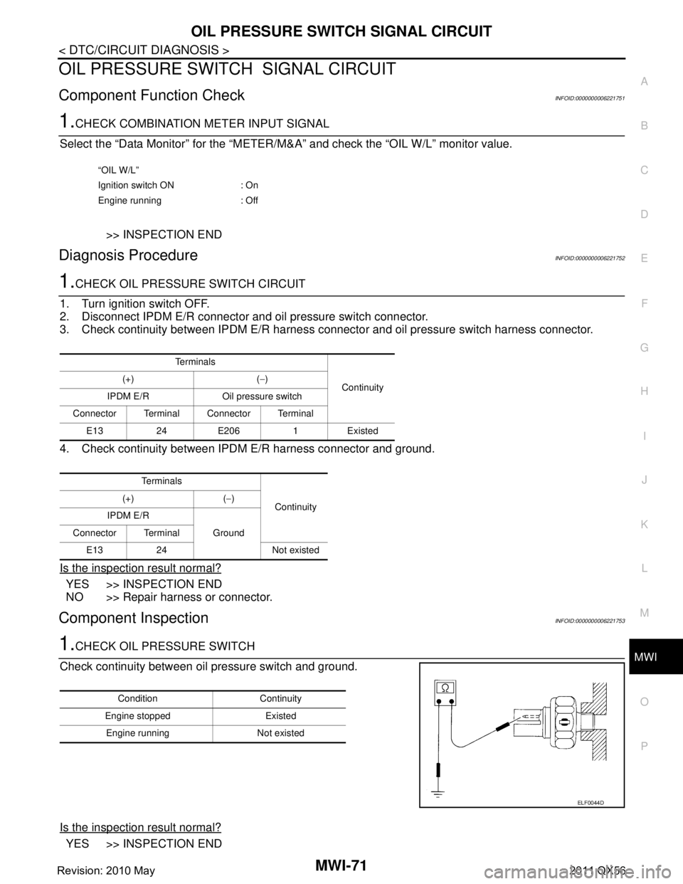
OIL PRESSURE SWITCH SIGNAL CIRCUIT
Component Function CheckINFOID:0000000006221751
1.CHECK COMBINATION METER INPUT SIGNAL
Select the “Data Monitor” for the “METER/M& A” and check the “OIL W/L” monitor value.
>> INSPECTION END
Diagnosis ProcedureINFOID:0000000006221752
1.CHECK OIL PRESSURE SWITCH CIRCUIT
1. Turn ignition switch OFF.
2. Disconnect IPDM E/R connector and oil pressure switch connector.
3. Check continuity between IPDM E/R harness c onnector and oil pressure switch harness connector.
4. Check continuity between IPDM E/R harness connector and ground.
Is the inspection result normal?
YES >> INSPECTION END
NO >> Repair harness or connector.
Component InspectionINFOID:0000000006221753
1.CHECK OIL PRESSURE SWITCH
Check continuity between oil pressure switch and ground.
Is the inspection result normal?
YES >> INSPECTION END
“OIL W/L”
Ignition switch ON : On
Engine running : Off
Te r m i n a l s Continuity
(+) (
−)
IPDM E/R Oil pressure switch
Connector Terminal Connector Terminal E1324E2061Existed
Te r m i n a l s Continuity
(+) (
−)
IPDM E/R Ground
Connector Terminal
E13 24 Not existed
Condition Continuity
Engine stopped Existed Engine running Not existed
ELF0044D
Revision: 2010 May2011 QX56
Page 3821 of 5598

MWI-78
< SYMPTOM DIAGNOSIS >
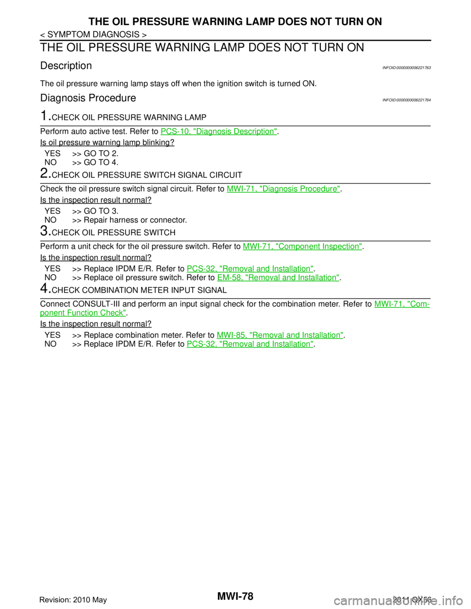
THE OIL PRESSURE WARNING LAMP DOES NOT TURN ON
THE OIL PRESSURE WARNING LAMP DOES NOT TURN ON
DescriptionINFOID:0000000006221763
The oil pressure warning lamp stays off when the ignition switch is turned ON.
Diagnosis ProcedureINFOID:0000000006221764
1.CHECK OIL PRESSURE WARNING LAMP
Perform auto active test. Refer to PCS-10, "
Diagnosis Description".
Is oil pressure warning lamp blinking?
YES >> GO TO 2.
NO >> GO TO 4.
2.CHECK OIL PRESSURE SWITCH SIGNAL CIRCUIT
Check the oil pressure switch signal circuit. Refer to MWI-71, "
Diagnosis Procedure".
Is the inspection result normal?
YES >> GO TO 3.
NO >> Repair harness or connector.
3.CHECK OIL PRESSURE SWITCH
Perform a unit check for the oil pressure switch. Refer to MWI-71, "
Component Inspection".
Is the inspection result normal?
YES >> Replace IPDM E/R. Refer to PCS-32, "Removal and Installation".
NO >> Replace oil pressure switch. Refer to EM-58, "
Removal and Installation".
4.CHECK COMBINATION METER INPUT SIGNAL
Connect CONSULT-III and perform an input signal check for the combination meter. Refer to MWI-71, "
Com-
ponent Function Check".
Is the inspection result normal?
YES >> Replace combination meter. Refer to MWI-85, "Removal and Installation".
NO >> Replace IPDM E/R. Refer to PCS-32, "
Removal and Installation".
Revision: 2010 May2011 QX56
Page 3822 of 5598

MWI
THE OIL PRESSURE WARNING LAMP DOES NOT TURN OFFMWI-79
< SYMPTOM DIAGNOSIS >
C
DE
F
G H
I
J
K L
M B A
O P
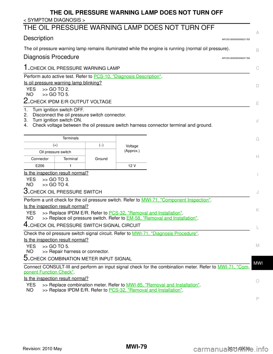
THE OIL PRESSURE WARNING LAMP DOES NOT TURN OFF
DescriptionINFOID:0000000006221765
The oil pressure warning lamp remains illuminated while the engine is running (normal oil pressure).
Diagnosis ProcedureINFOID:0000000006221766
1.CHECK OIL PRESSURE WARNING LAMP
Perform auto active test. Refer to PCS-10, "
Diagnosis Description".
Is oil pressure warning lamp blinking?
YES >> GO TO 2.
NO >> GO TO 5.
2.CHECK IPDM E/R OUTPUT VOLTAGE
1. Turn ignition switch OFF.
2. Disconnect the oil pressure switch connector.
3. Turn ignition switch ON.
4. Check voltage between the oil pressure switch harness connector terminal and ground.
Is the inspection result normal?
YES >> GO TO 3.
NO >> GO TO 4.
3.CHECK OIL PRESSURE SWITCH
Perform a unit check for the oil pressure switch. Refer to MWI-71, "
Component Inspection".
Is the inspection result normal?
YES >> Replace IPDM E/R. Refer to PCS-32, "Removal and Installation".
NO >> Replace oil pressure switch. Refer to EM-58, "
Removal and Installation".
4.CHECK OIL PRESSURE SWITCH SIGNAL CIRCUIT
Check the oil pressure switch signal circuit. Refer to MWI-71, "
Diagnosis Procedure".
Is the inspection result normal?
YES >> GO TO 5.
NO >> Repair harness or connector.
5.CHECK COMBINATION METER INPUT SIGNAL
Connect CONSULT-III and perform an input signal check for the combination meter. Refer to MWI-71, "
Com-
ponent Function Check".
Is the inspection result normal?
YES >> Replace combination meter. Refer to MWI-85, "Removal and Installation".
NO >> Replace IPDM E/R. Refer to PCS-32, "
Removal and Installation".
Te r m i n a l s
Voltag e
(Approx.)
(+) (
−)
Oil pressure switch Ground
Connector Terminal
E206 1 12 V
Revision: 2010 May2011 QX56
Page 3851 of 5598
![INFINITI QX56 2011 Factory Service Manual
PCS-10
< SYSTEM DESCRIPTION >[IPDM E/R]
DIAGNOSIS SYSTEM (IPDM E/R)
DIAGNOSIS SYSTEM (IPDM E/R)
Diagnosis DescriptionINFOID:0000000006220170
AUTO ACTIVE TEST
Description
In auto active test, the IPDM INFINITI QX56 2011 Factory Service Manual
PCS-10
< SYSTEM DESCRIPTION >[IPDM E/R]
DIAGNOSIS SYSTEM (IPDM E/R)
DIAGNOSIS SYSTEM (IPDM E/R)
Diagnosis DescriptionINFOID:0000000006220170
AUTO ACTIVE TEST
Description
In auto active test, the IPDM](/manual-img/42/57033/w960_57033-3850.png)
PCS-10
< SYSTEM DESCRIPTION >[IPDM E/R]
DIAGNOSIS SYSTEM (IPDM E/R)
DIAGNOSIS SYSTEM (IPDM E/R)
Diagnosis DescriptionINFOID:0000000006220170
AUTO ACTIVE TEST
Description
In auto active test, the IPDM E/R sends a drive si
gnal to the following systems to check their operation.
Oil pressure warning lamp
Rear window defogger
Front wiper (LO, HI)
Parking lamp
License plate lamp
Tail lamp
Side marker lamp
Front fog lamp
Headlamp (LO, HI)
A/C compressor (magnet clutch)
Operation Procedure
CAUTION:
Never perform auto active test in the following conditions.
Engine is running.
CONSULT-III is connected.
1. Close the hood and lift the wiper arms from the windshield. (Prevent windshield damage due to wiper
operation)
NOTE:
When auto active test is performed with hood opened, sprinkle water on windshield beforehand.
2. Turn the ignition switch OFF.
3. Turn the ignition switch ON, and within 20 seconds, pr ess the driver door switch 10 times. Then turn the
ignition switch OFF.
CAUTION:
Close passenger door.
4. Turn the ignition switch ON within 10 seconds. Af ter that the horn sounds once and the auto active test
starts.
CAUTION:
Engine starts when igniti on switch is turned ON while brake pedal is depressed.
5. The oil pressure warning lamp starts blinking when the auto active test starts.
6. After a series of the following operations is repeated 3 times, auto active test is completed.
NOTE:
When auto active test has to be cancelled halfway through test, turn the ignition switch OFF.
When auto active test is not activated, door swit ch may be the cause. Check door switch. Refer to DLK-117,
"ComponentFunctionCheck".
Inspection in Auto Active Test
When auto active test is actuated, the following operation sequence is repeated 3 times.
Operation
sequence Inspection location Operation
1 Oil pressure warning lamp Blinks continuously during operation of auto active test
2 Rear window defogger 10 seconds
3 Front wiper LO for 5 seconds → HI for 5 seconds
4 Parking lamp
License plate lamp
Tail lamp
Side marker lamp
Front fog lamp 10 seconds
Revision: 2010 May2011 QX56
Page 3853 of 5598
![INFINITI QX56 2011 Factory Service Manual
PCS-12
< SYSTEM DESCRIPTION >[IPDM E/R]
DIAGNOSIS SYSTEM (IPDM E/R)
CONSULT-III Function (IPDM E/R)
INFOID:0000000006220171
APPLICATION ITEM
CONSULT-III performs the following functions via CAN commu INFINITI QX56 2011 Factory Service Manual
PCS-12
< SYSTEM DESCRIPTION >[IPDM E/R]
DIAGNOSIS SYSTEM (IPDM E/R)
CONSULT-III Function (IPDM E/R)
INFOID:0000000006220171
APPLICATION ITEM
CONSULT-III performs the following functions via CAN commu](/manual-img/42/57033/w960_57033-3852.png)
PCS-12
< SYSTEM DESCRIPTION >[IPDM E/R]
DIAGNOSIS SYSTEM (IPDM E/R)
CONSULT-III Function (IPDM E/R)
INFOID:0000000006220171
APPLICATION ITEM
CONSULT-III performs the following functions via CAN communication with IPDM E/R.
SELF DIAGNOSTIC RESULT
Refer to PCS-22, "DTCIndex".
DATA MONITOR
Monitor item
Oil pressure warning lamp does not operate Perform auto active test.
Does the oil pressure warning
lamp blink?YES
Harness or connector be-
tween IPDM E/R and oil
pressure switch
Oil pressure switch
IPDM E/R
NO CAN communication signal
between IPDM E/R and
BCM
CAN communication signal
between BCM and combi-
nation meter
Combination meter
Symptom Inspection contents Possible cause
Diagnosis mode Description
Ecu Identification Allows confirmation of IPDM E/R part number.
Self Diagnostic Result Displays the diagnosis results judged by IPDM E/R.
Data Monitor Displays the real-time input/output data from IPDM E/R input/output data.
Active Test IPDM E/R can provide a drive signal to electronic components to check their operations.
CAN Diag Support Monitor The results of transmit/receive diagnosis of CAN communication can be read.
Monitor Item [Unit] MAIN SIG-
NALS Description
RAD FAN REQ
[1/2/3/4] ×Displays the value of the cooling fan speed request signal received from ECM via
CAN communication.
AC COMP REQ
[Off/On] ×Displays the status of the A/C compressor request signal received from ECM via
CAN communication.
TA I L & C L R R E Q
[Off/On] ×
Displays the status of the position light request signal received from BCM via CAN
communication.
HL LO REQ
[Off/On] ×Displays the status of the low beam request signal received from BCM via CAN
communication.
HL HI REQ
[Off/On] ×Displays the status of the high beam request signal received from BCM via CAN
communication.
FR FOG REQ
[Off/On] ×Displays the status of the front fog light request signal received from BCM via
CAN communication.
FR WIP REQ
[Stop/1LOW/Low/Hi] ×
Displays the status of the front wiper request signal received from BCM via CAN
communication.
WIP AUTO STOP
[STOP P/ACT P] ×
Displays the status of the front wiper auto stop signal judged by IPDM E/R.
WIP PROT
[Off/BLOCK] ×
Displays the status of the front wiper fail-safe operation judged by IPDM E/R.
IGN RLY1 -REQ
[Off/On] Displays the status of the ignition switch ON signal received from BCM via CAN
communication.
IGN RLY
[Off/On] ×
Displays the status of the ignition relay judged by IPDM E/R.
Revision: 2010 May2011 QX56
Page 3870 of 5598
![INFINITI QX56 2011 Factory Service Manual
PCS
B2098 IGNITION RELAY ON STUCKPCS-29
< DTC/CIRCUIT DIAGNOSIS > [IPDM E/R]
C
D
E
F
G H
I
J
K L
B A
O P
N
B2098 IGNITION RELAY ON STUCK
DescriptionINFOID:0000000006220179
IPDM E/R operates the ign INFINITI QX56 2011 Factory Service Manual
PCS
B2098 IGNITION RELAY ON STUCKPCS-29
< DTC/CIRCUIT DIAGNOSIS > [IPDM E/R]
C
D
E
F
G H
I
J
K L
B A
O P
N
B2098 IGNITION RELAY ON STUCK
DescriptionINFOID:0000000006220179
IPDM E/R operates the ign](/manual-img/42/57033/w960_57033-3869.png)
PCS
B2098 IGNITION RELAY ON STUCKPCS-29
< DTC/CIRCUIT DIAGNOSIS > [IPDM E/R]
C
D
E
F
G H
I
J
K L
B A
O P
N
B2098 IGNITION RELAY ON STUCK
DescriptionINFOID:0000000006220179
IPDM E/R operates the ignition relay when it receives
an ignition switch ON signal from BCM via CAN com-
munication.
Turn the ignition relay OFF by pressing the push-butt on ignition switch once when the vehicle speed is 4 km/
h (2.5 MPH) or less.
Turn the ignition relay OFF with the following operat ion when the vehicle speed is more than 4 km/h (2.5
MPH) or when an abnormal condition occurs in CAN communication from the combination meter (Emer-
gency OFF)
- Press and hold the push-button ignition switch for 2 seconds or more.
- Press the push-button ignition switch 3 times within 1.5 seconds.
NOTE:
The ignition relay does not turn ON for 3 seconds af ter emergency OFF even if the push-button ignition switch
is pressed.
DTC LogicINFOID:0000000006220180
DTC DETECTION LOGIC
Diagnosis ProcedureINFOID:0000000006220181
1.PERFORM SELF DIAGNOSIS
1. Turn the ignition switch ON.
2. Erase “Self Diagnostic Result” of IPDM E/R.
3. Turn the ignition switch OFF, and wait for 1 second or more.
4. Turn the ignition switch ON. Check “Self Diagnostic Result” again.
Is DTC
“B2098” displayed?
YES >> Replace IPDM E/R. Refer to PCS-32, "Removal and Installation".
NO >> Refer to GI-40, "
Intermittent Incident".
DTCCONSULT-III dis-
play description DTC Detection Condit
ion Possible causes
B2098 IGN RELAY ON The ignition relay ON is detected for 1 second at ignition switch OFF
(CPU monitors the status at the contact and excitation coil circuits
of the ignition relay inside it) Ignition relay malfunction
Revision: 2010 May2011 QX56