2011 INFINITI QX56 check oil
[x] Cancel search: check oilPage 3871 of 5598
![INFINITI QX56 2011 Factory Service Manual
PCS-30
< DTC/CIRCUIT DIAGNOSIS >[IPDM E/R]
B2099 IGNITION RELAY OFF STUCK
B2099 IGNITION RELAY OFF STUCK
DescriptionINFOID:0000000006220182
IPDM E/R operates the ignition relay when it receives
an INFINITI QX56 2011 Factory Service Manual
PCS-30
< DTC/CIRCUIT DIAGNOSIS >[IPDM E/R]
B2099 IGNITION RELAY OFF STUCK
B2099 IGNITION RELAY OFF STUCK
DescriptionINFOID:0000000006220182
IPDM E/R operates the ignition relay when it receives
an](/manual-img/42/57033/w960_57033-3870.png)
PCS-30
< DTC/CIRCUIT DIAGNOSIS >[IPDM E/R]
B2099 IGNITION RELAY OFF STUCK
B2099 IGNITION RELAY OFF STUCK
DescriptionINFOID:0000000006220182
IPDM E/R operates the ignition relay when it receives
an ignition switch ON signal from BCM via CAN com-
munication.
Turn the ignition relay OFF by pressing the push-butt on ignition switch once when the vehicle speed is 4 km/
h (2.5 MPH) or less.
Turn the ignition relay OFF with the following operati on when the vehicle speed is more than 4 km/h (2.5
MPH) or when an abnormal condition occurs in CAN communication from the combination meter (Emer-
gency OFF)
- Press and hold the push-button ignition switch for 2 seconds or more.
- Press the push-button ignition switch 3 times within 1.5 seconds.
NOTE:
The ignition relay does not turn ON for 3 seconds af ter emergency OFF even if the push-button ignition switch
is pressed.
DTC LogicINFOID:0000000006220183
DTC DETECTION LOGIC
NOTE:
When IPDM E/R power supply voltage is low (Approx. 7 - 8 V for about 1 second), the “DTC: B2099” may be detected.
Diagnosis ProcedureINFOID:0000000006220184
1.PERFORM SELF DIAGNOSIS
1. Turn the ignition switch ON.
2. Erase “Self Diagnostic Result”.
3. Turn the ignition switch OFF.
4. Turn the ignition switch ON. Check “Self Diagnostic Result” again.
Is DTC
“B2099” displayed?
YES >> Replace IPDM E/R. Refer to PCS-32, "Removal and Installation".
NO >> Refer to GI-40, "
Intermittent Incident".
DTCCONSULT-III dis-
play description DTC Detection Condit
ion Possible causes
B2099 IGN RELAY OFF The ignition relay OFF is detected for 1 second at ignition switch ON
(CPU monitors the status at the contact and excitation coil circuits of
the ignition relay inside it) Ignition relay malfunction
Revision: 2010 May2011 QX56
Page 4257 of 5598

RSU-2
< PRECAUTION >
PRECAUTIONS
PRECAUTION
PRECAUTIONS
Precautions for SuspensionINFOID:0000000006225656
• When installing rubber bushings, the final tightening must be carried out under unladen conditions with tires
on ground. Spilled oil might shorten the life of rubber bushings. Be sure to wipe off any spilled oil.
- Unladen conditions mean that fuel, engine coolant and l ubricant are full. Spare tire, jack, hand tools and
mats are in designated positions.
After servicing suspension parts, be sure to check wheel alignment.
Self-lock nuts are not reusable. Always use new ones when installing. Since new self-lock nuts are pre-oiled,
tighten as they are.
Revision: 2010 May2011 QX56
Page 4260 of 5598
REAR SUSPENSION ASSEMBLYRSU-5
< PERIODIC MAINTENANCE >
C
DF
G H
I
J
K L
M A
B
RSU
N
O P
PERIODIC MAINTENANCE
REAR SUSPENSION ASSEMBLY
InspectionINFOID:0000000006225660
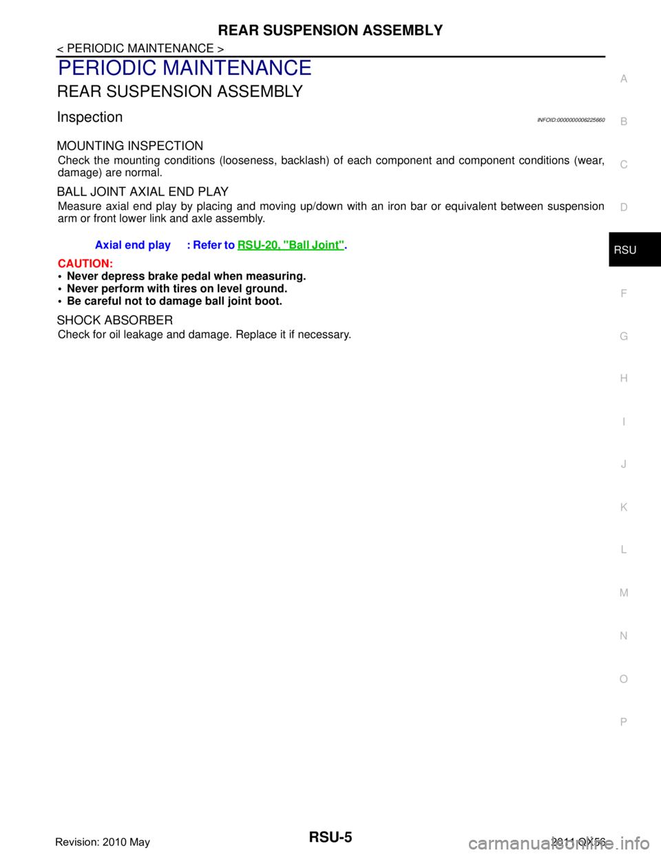
MOUNTING INSPECTION
Check the mounting conditions (looseness, backlash) of each component and component conditions (wear,
damage) are normal.
BALL JOINT AXIAL END PLAY
Measure axial end play by placing and moving up/down with an iron bar or equivalent between suspension
arm or front lower link and axle assembly.
CAUTION:
• Never depress brake pedal when measuring.
Never perform with tires on level ground.
Be careful not to damage ball joint boot.
SHOCK ABSORBER
Check for oil leakage and damage. Replace it if necessary. Axial end play : Refer to
RSU-20, "
Ball Joint".
Revision: 2010 May2011 QX56
Page 4264 of 5598
REAR LOWER LINK & COIL SPRINGRSU-9
< REMOVAL AND INSTALLATION >
C
DF
G H
I
J
K L
M A
B
RSU
N
O P
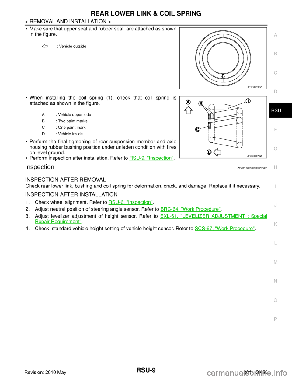
Make sure that upper seat and rubber seat are attached as shown in the figure.
When installing the coil spring (1), check that coil spring is attached as shown in the figure.
Perform the final tightening of rear suspension member and axle housing rubber bushing position under unladen condition with tires
on level ground.
Perform inspection after installation. Refer to RSU-9, "
Inspection".
InspectionINFOID:0000000006225665
INSPECTION AFTER REMOVAL
Check rear lower link, bushing and coil spring for defor mation, crack, and damage. Replace it if necessary.
INSPECTION AFTER INSTALLATION
1. Check wheel alignment. Refer to RSU-6, "Inspection".
2. Adjust neutral position of steering angle sensor. Refer to BRC-64, "
Work Procedure".
3. Adjust levelizer adjustment of height sensor. Refer to EXL-61, "
LEVELIZER ADJUSTMENT : Special
Repair Requirement".
4. Check standard vehicle height setting of vehicle height sensor. Refer to SCS-67, "
Work Procedure".
: Vehicle outside
JPEIB0219ZZ
A : Vehicle upper side
B : Two paint marks
C : One paint mark
D : Vehicle inside
JPEIB0237ZZ
Revision: 2010 May2011 QX56
Page 4266 of 5598
REAR SHOCK ABSORBERRSU-11
< REMOVAL AND INSTALLATION >
C
DF
G H
I
J
K L
M A
B
RSU
N
O P
Inadvertent piping removal causes fluid to splatter.
2. Remove tires with power tool. Refer to WT-64, "
Removal and Installation".
3. Remove height sensor from rear lower link (right side). Refer to EXL-136, "
Removal and Installation".
4. Remove vehicle height sensor from rear lower link (left side). Refer to SCS-98, "
Removal and Installa-
tion".
5. Remove air tube from shock absorber assembly. Refer to SCS-95, "
Removal and Installation".
6. Remove middle tube assembly from shock absorber assembly. (With HBMC) Refer to SCS-44, "
REAR
TUBE ASSEMBLY : Removal and Installation".
7. Remove shock absorber mounting bolt (lower side).
8. Remove piston rod lock nut.
9. Remove bracket, bushings, and shock absorber. (With HBMC)
10. Remove washers, bushings, and shock absorber. (Without HBMC)
11. Perform inspection after removal. Refer to RSU-11, "
Inspection and Adjustment".
INSTALLATION
Note the following, and install in the reverse order of removal.
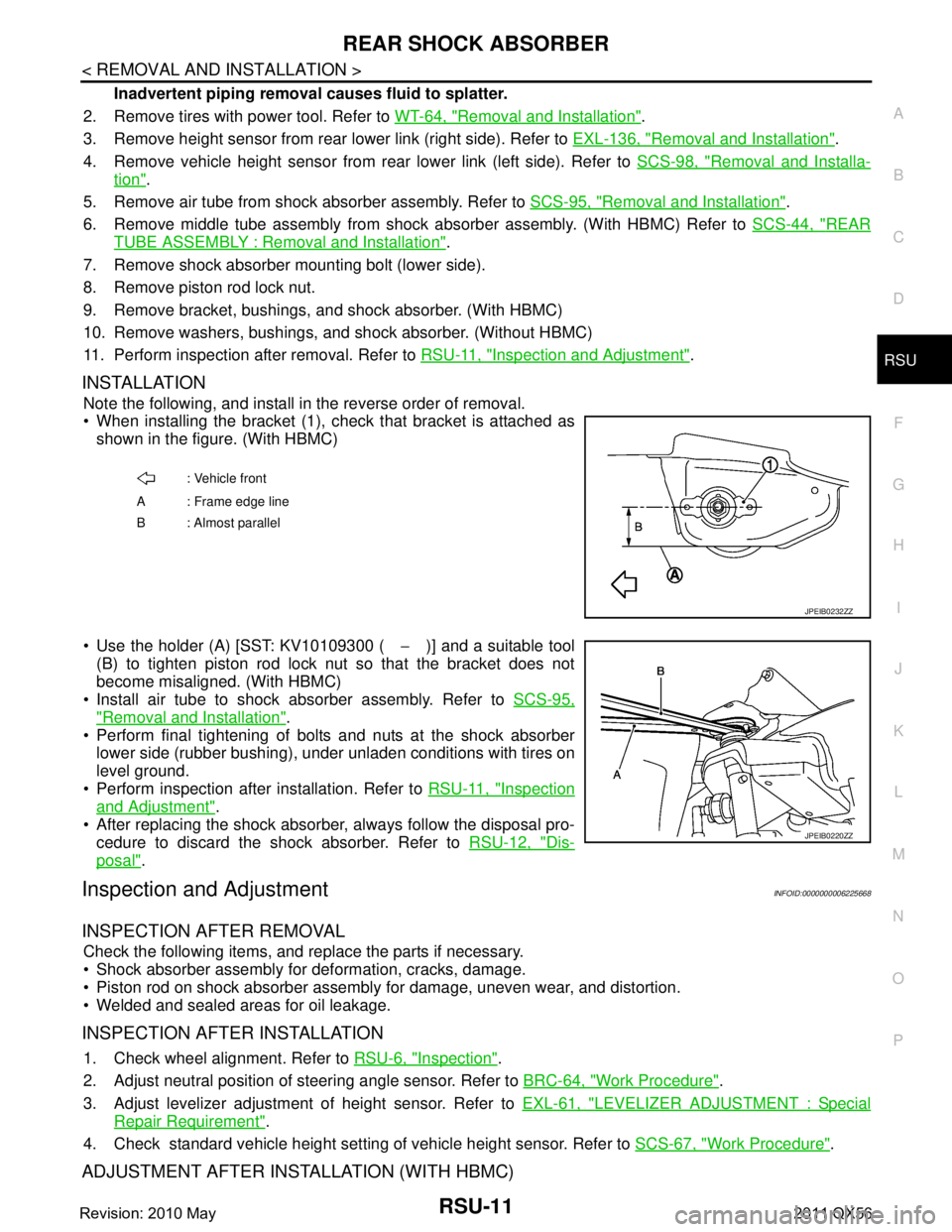
When installing the bracket (1), check that bracket is attached as
shown in the figure. (With HBMC)
Use the holder (A) [SST: KV10109300 ( −)] and a suitable tool
(B) to tighten piston rod lock nut so that the bracket does not
become misaligned. (With HBMC)
Install air tube to shock absorber assembly. Refer to SCS-95,
"Removal and Installation".
Perform final tightening of bolts and nuts at the shock absorber
lower side (rubber bushing), under unladen conditions with tires on
level ground.
Perform inspection after installation. Refer to RSU-11, "
Inspection
and Adjustment".
After replacing the shock absorber, always follow the disposal pro- cedure to discard the shock absorber. Refer to RSU-12, "
Dis-
posal".
Inspection and AdjustmentINFOID:0000000006225668
INSPECTION AFTER REMOVAL
Check the following items, and replace the parts if necessary.
Shock absorber assembly for deformation, cracks, damage.
Piston rod on shock absorber assembly for damage, uneven wear, and distortion.
Welded and sealed areas for oil leakage.
INSPECTION AFTER INSTALLATION
1. Check wheel alignment. Refer to RSU-6, "Inspection".
2. Adjust neutral position of steering angle sensor. Refer to BRC-64, "
Work Procedure".
3. Adjust levelizer adjustment of height sensor. Refer to EXL-61, "
LEVELIZER ADJUSTMENT : Special
Repair Requirement".
4. Check standard vehicle height setting of vehicle height sensor. Refer to SCS-67, "
Work Procedure".
ADJUSTMENT AFTER INSTALLATION (WITH HBMC)
: Vehicle front
A : Frame edge line
B: Almost parallel
JPEIB0232ZZ
JPEIB0220ZZ
Revision: 2010 May2011 QX56
Page 4278 of 5598
PRECAUTIONSSB-3
< PRECAUTION >
C
DE
F
G
I
J
K L
M A
B
SB
N
O P
5. When the repair work is completed, re-connect both battery cables. With the brake pedal released, turn
the push-button ignition switch from ACC position to ON position, then to LOCK position. (The steering
wheel will lock when the push-button ignition switch is turned to LOCK position.)
6. Perform self-diagnosis check of a ll control units using CONSULT-III.
Precaution for Seat Belt ServiceINFOID:0000000006217608
CAUTION:
Before removing the front seat belt pre-tensioner assembly, turn the ignition switch off, disconnect
battery negative terminal and wait at least 3 minutes.
Never use electrical test equipment for front seat belt pre-tensioner connector.
After replacing or reinstalling front seat belt pre-tensioner assembly, or reconnecting front seat belt
pre-tensioner connector, check th e system function. Refer to SRC-14, "
Description".
Never use disassembled buckle or seat belt assembly.
Replace anchor bolts if th ey are deformed or worn out.
Never oil tongue and buckle.
If any component of seat belt assembly is questiona ble, do not repair. Replace the entire seat belt
assembly.
If webbing is cut, frayed or damaged, replace seat belt assembly.
When replacing seat belt assembly, u se a genuine NISSAN seat belt assembly.
AFTER A COLLISION
WARNING:
Inspect all seat belt assemblies including retractors and attached hardware after any collision.
NISSAN recommends that all seat belt assemblies in u se during a collision be replaced unless the col-
lision was minor and the belts show no damage a nd continue to operate properly. Failure to do so
could result in serious personal injury in an accide nt. Seat belt assemblies not in use during a colli-
sion should also be replaced if either damage or im proper operation is noted. Seat belt pre-tensioners
should be replaced even if the seat belts are not in use during a frontal collision in which the air bags
are deployed.
Replace any seat belt assembly (including anchor bolts) if:
The seat belt was in use at the time of a collision (except for minor collisions and the belts, retractors and
buckles show no damage and continue to operate properly).
The seat belt was damaged in an accident (i.e. torn webbing, bent retractor or guide).
The seat belt attaching point was damaged in an accident. Inspect the seat belt attaching area for damage or distortion and repair as necessary before installing a new seat belt assembly.
Anchor bolts are deformed or worn out.
The front seat belt pre-tensioner should be replaced even if the seat belts are not in use during the collision
in which the air bags are deployed.
Revision: 2010 May2011 QX56
Page 4300 of 5598
PRECAUTIONSSBC-3
< PRECAUTION >
C
DE
F
G
I
J
K L
M A
B
SBC
N
O P
PRECAUTION
PRECAUTIONS
Precaution for Supplemental Restraint System (SRS) "AIR BAG" and "SEAT BELT
PRE-TENSIONER"
INFOID:0000000006237873
The Supplemental Restraint System such as “A IR BAG” and “SEAT BELT PRE-TENSIONER”, used along
with a front seat belt, helps to reduce the risk or severi ty of injury to the driver and front passenger for certain
types of collision. This system includes seat belt switch inputs and dual stage front air bag modules. The SRS
system uses the seat belt switches to determine the front air bag deployment, and may only deploy one front
air bag, depending on the severity of a collision and whether the front occupants are belted or unbelted.
Information necessary to service the system safely is included in the “SRS AIR BAG” and “SEAT BELT” of this
Service Manual.
WARNING:
• To avoid rendering the SRS inoper ative, which could increase the risk of personal injury or death in
the event of a collision that would result in air ba g inflation, all maintenance must be performed by
an authorized NISSAN/INFINITI dealer.
Improper maintenance, including in correct removal and installation of the SRS, can lead to personal
injury caused by unintentional act ivation of the system. For removal of Spiral Cable and Air Bag
Module, see the “SRS AIR BAG”.
Do not use electrical test equipm ent on any circuit related to the SRS unless instructed to in this
Service Manual. SRS wiring harnesses can be identi fied by yellow and/or orange harnesses or har-
ness connectors.
PRECAUTIONS WHEN USING POWER TOOLS (AIR OR ELECTRIC) AND HAMMERS
WARNING:
When working near the Air Bag Diagnosis Sensor Unit or other Air Bag System sensors with the
ignition ON or engine running, DO NOT use air or electric power tools or strike near the sensor(s)
with a hammer. Heavy vibration could activate the sensor(s) and deploy the air bag(s), possibly
causing serious injury.
When using air or electric power tools or hammers , always switch the ignition OFF, disconnect the
battery, and wait at least 3 minutes before performing any service.
Precaution for Seat Belt ServiceINFOID:0000000006237874
CAUTION:
Before removing the seat belt pre-tensioner assembly, turn the ignition switch off, disconnect the
both battery cables and wait at least 3 minutes.
Do not use electrical test equipment for seat belt pre-tensioner connector.
After replacing or reinstalling seat belt pre-tens ioner assembly, or reconnecting front seat belt pre-
tensioner connector, check the system function. Refer to SRC-11, "
System Diagram".
Do not use disassemble buckle or seat belt assembly.
Replace anchor bolts if th ey are deformed or worn out.
Never oil tongue and buckle.
If any component of seat belt assembly is questio nable, do not repair. Replace the whole seat belt
assembly.
If webbing is cut, frayed, or damaged, replace seat belt assembly.
When replacing seat belt assembly, u se a genuine NISSAN seat belt assembly.
AFTER A COLLISION
WARNING:
Inspect all seat belt assemblies including retractors and attaching hardware after any collision.
NISSAN recommends that all seat belt assemblies in u se during a collision be replaced unless the col-
lision was minor and the belts show no damage a nd continue to operate properly. Failure to do so
could result in serious personal injury in an accide nt. Seat belt assemblies not in use during a colli-
sion should also be replaced if either damage or im proper operation is noted. Seat belt pre-tensioner
should be replaced even if the seat belts are not in use during a frontal collision in which the air bags
are deployed.
Replace any seat belt assembly (including anchor bolts) if:
Revision: 2010 May2011 QX56
Page 4365 of 5598
![INFINITI QX56 2011 Factory Service Manual
PRECAUTIONSSCS-5
< PRECAUTION > [HBMC]
C
D
F
G H
I
J
K L
M A
B
SCS
N
O P
5. When the repair work is completed, re-connect both battery cables. With the brake pedal released, turn
the push-button ign INFINITI QX56 2011 Factory Service Manual
PRECAUTIONSSCS-5
< PRECAUTION > [HBMC]
C
D
F
G H
I
J
K L
M A
B
SCS
N
O P
5. When the repair work is completed, re-connect both battery cables. With the brake pedal released, turn
the push-button ign](/manual-img/42/57033/w960_57033-4364.png)
PRECAUTIONSSCS-5
< PRECAUTION > [HBMC]
C
D
F
G H
I
J
K L
M A
B
SCS
N
O P
5. When the repair work is completed, re-connect both battery cables. With the brake pedal released, turn
the push-button ignition switch from ACC position to ON position, then to LOCK position. (The steering
wheel will lock when the push-button ignition switch is turned to LOCK position.)
6. Perform self-diagnosis check of a ll control units using CONSULT-III.
Precaution for Procedure without Cowl Top CoverINFOID:0000000006256138
When performing the procedure after removing cowl top cover, cover
the lower end of windshield with urethane, etc.
Precaution for Hydraulic Body-Motion Control SystemINFOID:0000000006255996
WARNING:
Always check the piping for loose co nnections, damage, or twists before starting operation, since
pressure in hydraulic circuit becom es high during air bleeding operation.
When repairing or replacing a malfunctioning pa rt, always release pressure from hydraulic circuit,
since dangerous conditions may be created when oil leakage occurs during air bleeding operation.
Clean surrounding areas of oil inlet and air bleeder usi ng steam before starting operation, since there may
be mud on it.
Always decrease pressure when removing a system related part, since system pressure is high.
Seal the removed part using vinyl tape for preventi ng dirt from getting on or entering the removed part.
Check system pressure again 1 day or more after bleeding operation is complete, since system pressure may decrease when air bleeding is insufficient.
Use Genuine NISSAN Hydraulic Suspension Fluid for suspension fluid.
Never reuse drained suspension fluid.
Check for suspension fluid leakage after removing a system-related part.
PIIB3706J
Revision: 2010 May2011 QX56