2011 INFINITI QX56 check oil
[x] Cancel search: check oilPage 2654 of 5598
![INFINITI QX56 2011 Factory Service Manual
EM-92
< REMOVAL AND INSTALLATION >
CYLINDER HEAD
a. Apply new engine oil on new valve oil seal joint and seal lip.
b. Using the valve oil seal drift [SST: KV10115600 (J-38958)] (A),press fit valve se INFINITI QX56 2011 Factory Service Manual
EM-92
< REMOVAL AND INSTALLATION >
CYLINDER HEAD
a. Apply new engine oil on new valve oil seal joint and seal lip.
b. Using the valve oil seal drift [SST: KV10115600 (J-38958)] (A),press fit valve se](/manual-img/42/57033/w960_57033-2653.png)
EM-92
< REMOVAL AND INSTALLATION >
CYLINDER HEAD
a. Apply new engine oil on new valve oil seal joint and seal lip.
b. Using the valve oil seal drift [SST: KV10115600 (J-38958)] (A),press fit valve seal to height (b) shown in figure.
4. Install valve. NOTE:
Larger diameter valves are for intake side.
5. Install valve spring (with valve spring seat). Install narrow pitch (B) end [paint mark (C)] to cylinder headside (valve spring seat side).
6. Install valve spring retainer.
7. Install valve collet. Compress valve spring with the valve spring compressor [SST:
KV10116200 (J26336-A)] (A), the attachment [SST:
KV10115900 (J26336-20)] (C) and the adapter [SST:
KV10109220 ( — )] (B). Install valve collet with a magnet
hand.
CAUTION:
When working, take care not to damage valve lifter holes.
Tap valve stem edge lightly with plastic hammer after installa- tion to check its installed condition.
InspectionINFOID:0000000006289573
INSPECTION AFTER DISASSEMBLY
Cylinder Head Bolt s Outer Diameter
Cylinder head bolts are tightened by plastic zone tightening
method. Whenever the size difference between (B) and (A)
exceeds the limit, replace them with new one.
If reduction of outer diameter appears in a position other than (A),
use it as (A) point. Height (b)
Intake, Exhaust : 14.3 - 14.9 mm (0.563 - 0.587 in)
JPBIA1367ZZ
A : Wide pitch
: Cylinder head side
Paint mark color
Intake : Light green
Exhaust : Light blue
JPBIA0179ZZ
JPBIA1365ZZ
Limit [(B) - (A)] : 0.18 mm (0.0071 in)
c : 55 mm (2.17 in)
d : 12 mm (0.47 in)
JPBIA2144ZZ
Revision: 2010 May2011 QX56
Page 2655 of 5598
CYLINDER HEADEM-93
< REMOVAL AND INSTALLATION >
C
DE
F
G H
I
J
K L
M A
EM
NP
O
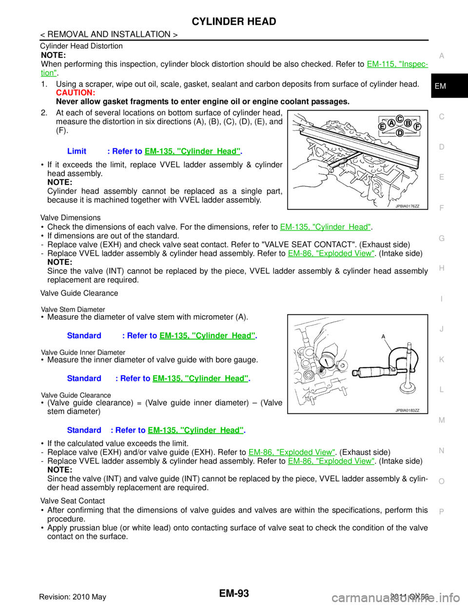
Cylinder Head Distortion
NOTE:
When performing this inspection, cylinder block distortion should be also checked. Refer to
EM-115, "
Inspec-
tion".
1. Using a scraper, wipe out oil, scale, gasket, s ealant and carbon deposits from surface of cylinder head.
CAUTION:
Never allow gasket fragments to enter engine oil or engine coolant passages.
2. At each of several locations on bottom surface of cylinder head, measure the distortion in six directi ons (A), (B), (C), (D), (E), and
(F).
If it exceeds the limit, replace VVEL ladder assembly & cylinder head assembly.
NOTE:
Cylinder head assembly cannot be replaced as a single part,
because it is machined together with VVEL ladder assembly.
Valve Dimensions
Check the dimensions of each valv e. For the dimensions, refer to EM-135, "CylinderHead".
If dimensions are out of the standard.
- Replace valve (EXH) and check valve seat contact. Refer to "VALVE SEAT CONTACT". (Exhaust side)
- Replace VVEL ladder assembly & cylinder head assembly. Refer to EM-86, "
Exploded View". (Intake side)
NOTE:
Since the valve (INT) cannot be replaced by the pi ece, VVEL ladder assembly & cylinder head assembly
replacement are required.
Valve Guide Clearance
Valve Stem Diameter
Measure the diameter of valve stem with micrometer (A).
Valve Guide Inner Diameter
Measure the inner diameter of valve guide with bore gauge.
Valve Guide Clearance
(Valve guide clearance) = (Valve guide inner diameter) – (Valve
stem diameter)
If the calculated value exceeds the limit.
- Replace valve (EXH) and/or valve guide (EXH). Refer to EM-86, "
Exploded View". (Exhaust side)
- Replace VVEL ladder assembly & cylinder head assembly. Refer to EM-86, "
Exploded View". (Intake side)
NOTE:
Since the valve (INT) and valve guide (INT) cannot be repl aced by the piece, VVEL ladder assembly & cylin-
der head assembly replacement are required.
Valve Seat Contact
After confirming that the dimensions of valve guides and valves are within the specifications, perform this
procedure.
Apply prussian blue (or white lead) onto contacting surfac e of valve seat to check the condition of the valve
contact on the surface. Limit : Refer to
EM-135, "
CylinderHead".
JPBIA0176ZZ
Standard : Refer to EM-135, "CylinderHead".
Standard : Refer to EM-135, "
CylinderHead".
Standard : Refer to EM-135, "
CylinderHead".
JPBIA0183ZZ
Revision: 2010 May2011 QX56
Page 2656 of 5598

EM-94
< REMOVAL AND INSTALLATION >
CYLINDER HEAD
Check if the contact area band is continuous all around the circum-ference.
- If not, grind to adjust valve fitting and check again. If the contacting surface still has “NG” conditions even after the re-check, replace
valve seat (EXH). Refer to EM-86, "
Exploded View". (Exhaust
side)
- If not, replace VVEL ladder assembly & cylinder head assembly. Refer to EM-86, "
Exploded View". (Intake side)
NOTE:
Since the valve seat (INT) cannot be replaced by t he piece, VVEL ladder assembly & cylinder head assem-
bly replacement are required.
Valve Spring (with valve spring seat) Squareness
Set a try square (A) along the side of valve spring (with valve
spring seat) and rotate spring. Measure the maximum clearance
between the top of spring and try square.
If it exceeds the limit.
- Replace valve spring (with valve spring seat) (EXH). Refer to EM-
86, "Exploded View". (Exhaust side)
- Replace VVEL ladder assembly & cylinder head assembly. Refer
to EM-86, "
Exploded View". (Intake side)
NOTE:
Since the valve spring (with valve spring seat) (INT) c annot be replaced by the piece, VVEL ladder assembly
& cylinder head assembly replacement are required.
Valve Spring Dimensions and Valve Spring Pressure Load
Check the valve spring (with valve spring seat) pressure at speci- fied spring height.
If the installation load or load with valve open is out of the stan- dard.
- Replace valve spring (with valve spring seat) (EXH). Refer to EM-
86, "Exploded View". (Exhaust side)
- Replace VVEL ladder assembly & cylinder head assembly. Refer to EM-86, "
Exploded View". (Intake side)
NOTE:
Since the valve spring (with valve spring seat) (INT) c annot be replaced by the piece, VVEL ladder assembly
& cylinder head assembly replacement are required.
INSPECTION AFTER ASSEMBLY
Inspection for Leakage
The following are procedures for checking fluid leakage, lubricant leakage.
Before starting engine, check oil/fluid levels includi ng engine coolant and engine oil. If any are less than the
required quantity, fill them to the specified level. Refer to MA-10, "
Fluids and Lubricants".
Follow the procedure below to check for fuel leakage.
- Turn ignition switch to the “ON” position (with engi ne stopped). With fuel pressure applied to fuel piping,
check for fuel leakage at connection points.
- Start engine. With engine speed increased, che ck again for fuel leakage at connection points.
Run engine to check for unusual noise and vibration. NOTE:
A: OK
B: NG
JPBIA0187ZZ
B : Contact
Limit : Refer to EM-135, "CylinderHead".
JPBIA0189ZZ
Standard
: Refer to EM-135, "
CylinderHead".
SEM113
Revision: 2010 May2011 QX56
Page 2657 of 5598
CYLINDER HEADEM-95
< REMOVAL AND INSTALLATION >
C
DE
F
G H
I
J
K L
M A
EM
NP
O
If hydraulic pressure inside chain tensioner drops after removal/installation, slack in guide may generate a
pounding noise during and just after the engine start. However, this does not indicate a malfunction. The
noise will stop after hydraulic pressure rises.
Warm up engine thoroughly to check that there is no leak age of fuel, or any oil/fluids including engine oil and
engine coolant.
Bleed air from lines and hoses of applicable lines, such as in cooling system.
After cooling down engine, again check oil/fluid levels including engine oil and engine coolant. Refill them to
the specified level, if necessary.
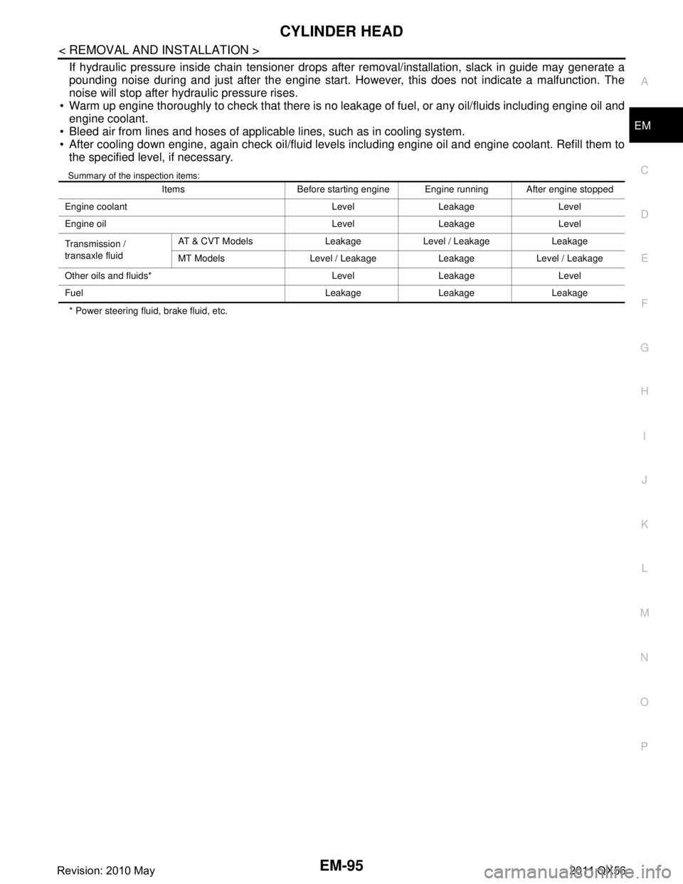
Summary of the inspection items:
* Power steering fluid, brake fluid, etc. Items Before starting engine Engine running After engine stopped
Engine coolant Level Leakage Level
Engine oil Level Leakage Level
Transmission /
transaxle fluid AT & CVT Models Leakage Level / Leakage Leakage
MT Models Level / Leakage Leakage Level / Leakage
Other oils and fluids* Level Leakage Level
Fuel Leakage Leakage Leakage
Revision: 2010 May2011 QX56
Page 2658 of 5598
EM-96
< REMOVAL AND INSTALLATION >
OIL SEAL
OIL SEAL
FRONT OIL SEAL
FRONT OIL SEAL : Removal and InstallationINFOID:0000000006289574
REMOVAL
1. Remove the following parts:
Front under cover, using a power tool. Refer to EXT-25, "
Exploded View".
Drive belt: Refer to EM-20, "
Exploded View".
Cooling fan: Refer to CO-16, "
Exploded View".
2. Remove crankshaft pulley as per the following:
a. Remove rear plate cover. Refer to EM-54, "
Exploded View".
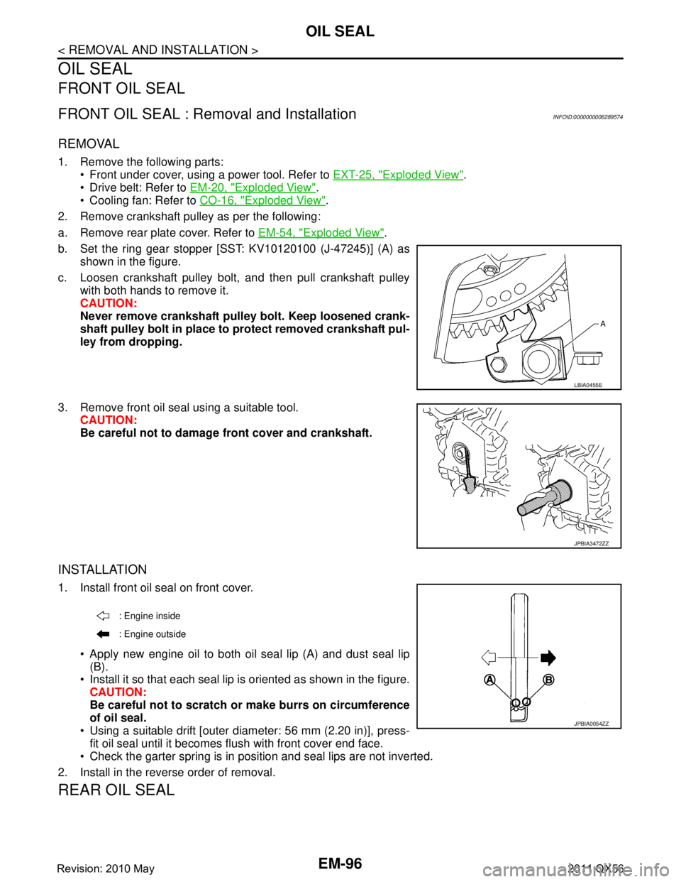
b. Set the ring gear stopper [SST: KV10120100 (J-47245)] (A) as shown in the figure.
c. Loosen crankshaft pulley bolt, and then pull crankshaft pulley with both hands to remove it.
CAUTION:
Never remove crankshaft pulley bolt. Keep loosened crank-
shaft pulley bolt in place to protect removed crankshaft pul-
ley from dropping.
3. Remove front oil seal using a suitable tool. CAUTION:
Be careful not to damage front cover and crankshaft.
INSTALLATION
1. Install front oil seal on front cover.
Apply new engine oil to both oil seal lip (A) and dust seal lip(B).
Install it so that each seal lip is oriented as shown in the figure. CAUTION:
Be careful not to scratch or make burrs on circumference
of oil seal.
Using a suitable drift [outer diameter: 56 mm (2.20 in)], press- fit oil seal until it becomes flush with front cover end face.
Check the garter spring is in position and seal lips are not inverted.
2. Install in the reverse order of removal.
REAR OIL SEAL
LBIA0455E
JPBIA3472ZZ
: Engine inside
: Engine outside
JPBIA0054ZZ
Revision: 2010 May2011 QX56
Page 2659 of 5598
OIL SEALEM-97
< REMOVAL AND INSTALLATION >
C
DE
F
G H
I
J
K L
M A
EM
NP
O
REAR OIL SEAL : Removal and InstallationINFOID:0000000006289575
REMOVAL
1. Remove transmission assembly. Refer to
TM-205, "2WD : Exploded View" (2WD models) or TM-208,
"4WD : Exploded View" (4WD models).
2. Remove drive plate. Refer to EM-106, "
Exploded View".
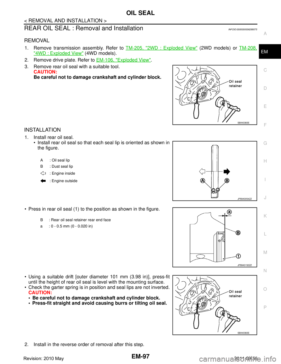
3. Remove rear oil seal with a suitable tool. CAUTION:
Be careful not to damage crankshaft and cylinder block.
INSTALLATION
1. Install rear oil seal. Install rear oil seal so that each seal lip is oriented as shown in
the figure.
Press in rear oil seal (1) to the position as shown in the figure.
Using a suitable drift [outer diameter 101 mm (3.98 in)], press-fit until the height of rear oil seal is level with the mounting surface.
Check the garter spring is in position and seal lips are not inverted. CAUTION:
Be careful not to damage crankshaft and cylinder block.
Press-fit straight and avoid cau sing burrs or tilting oil seal.
2. Install in the reverse order of removal after this step.
SBIA0360E
A : Oil seal lip
B : Dust seal lip : Engine inside
: Engine outside
JPBIA0054ZZ
B : Rear oil seal retainer rear end face
a : 0 - 0.5 mm (0 - 0.020 in)
JPBIA0152ZZ
SBIA0360E
Revision: 2010 May2011 QX56
Page 2663 of 5598
ENGINE ASSEMBLYEM-101
< UNIT REMOVAL AND INSTALLATION >
C
DE
F
G H
I
J
K L
M A
EM
NP
O
5. Remove A/T assembly. Refer to
TM-205, "2WD : Exploded View" (2WD models) or TM-208, "4WD :
Exploded View" (4WD models).
6. Remove steering gear assembly. Refer to ST-41, "
Exploded View".
7. Remove front final drive assembly. Refer to DLN-162, "
Exploded View".
8. Remove exhaust manifold. Refer to EM-40, "
Exploded View".
9. Remove alternator. Refer to CHG-25, "
Exploded View".
Engine Room LH
1. Remove air cleaner and air duct. Refer to EM-27, "Exploded View".
2. Remove A/C compressor. Refer to HA-30, "
Exploded View".
3. Disconnect fuel feed hose and EVAP hose. Refer to EM-43, "
Exploded View".
CAUTION:
Fit plugs onto disconnected hoses to prevent fuel leakage.
Engine Room RH
1. Remove power steering oil pump and reservoir tank. Refer to ST-48, "Exploded View".
2. Disconnect heater hose at heater core side, and fit a plug onto hose end to prevent engine coolant leak-
age.
3. Disconnect ground cable.
4. Disconnect all clips and connectors of the engine harness from vehicle side.
Removal Work
1. Install alternator bracket. Refer to CHG-25, "Exploded View".
Temporarily tighten mounting bolts.
2. Remove intake manifold. Refer to EM-30, "
Exploded View".
3. Remove starter motor. Refer to STR-17, "
Exploded View".
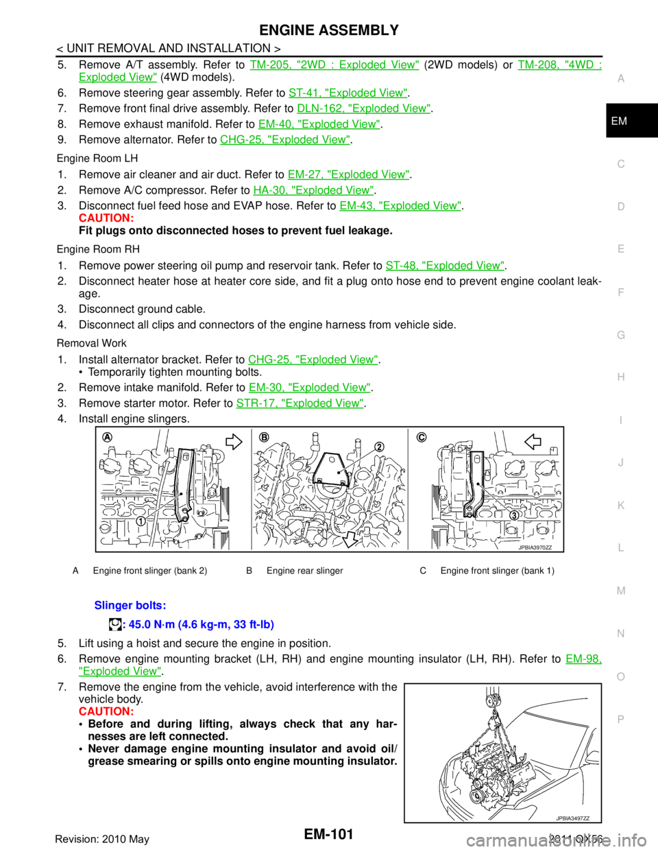
4. Install engine slingers.
5. Lift using a hoist and secure the engine in position.
6. Remove engine mounting bracket (LH, RH) and engine mounting insulator (LH, RH). Refer to EM-98,
"Exploded View".
7. Remove the engine from the vehi cle, avoid interference with the
vehicle body.
CAUTION:
Before and during lifting, always check that any har-
nesses are left connected.
Never damage engine mounti ng insulator and avoid oil/
grease smearing or spills onto engine mounting insulator.
A Engine front slinger (bank 2) B Engine rear slinger C Engine front slinger (bank 1)
Slinger bolts:
: 45.0 N·m (4.6 kg-m, 33 ft-lb)
JPBIA3970ZZ
JPBIA3497ZZ
Revision: 2010 May2011 QX56
Page 2664 of 5598
EM-102
< UNIT REMOVAL AND INSTALLATION >
ENGINE ASSEMBLY
INSTALLATION
Install in the reverse order of removal.
CAUTION:
When replacing an engine or transmission you must make sure the dowels are installed correctly
during re-assembly.Improper alignment caused by mi ssing dowels may cause vibration, oil leaks or
breakage of drivetrain components.
InspectionINFOID:0000000006289578
INSPECTION AFTER INSTALLATION
Inspection for Leakage
The following are procedures for checking fluid leakage, lubricant leakage. Before starting engine, check oil/fluid levels includi ng engine coolant and engine oil. If any are less than the
required quantity, fill them to the specified level. Refer to MA-10, "
Fluids and Lubricants".
Follow the procedure below to check for fuel leakage.
- Turn ignition switch to the “ON” position (with engi ne stopped). With fuel pressure applied to fuel piping,
check for fuel leakage at connection points.
- Start engine. With engine speed increased, che ck again for fuel leakage at connection points.
Run engine to check for unusual noise and vibration. NOTE:
If hydraulic pressure inside chain tensioner drops af ter removal/installation, slack in guide may generate a
pounding noise during and just after the engine start. However, this does not indicate a malfunction. The
noise will stop after hydraulic pressure rises.
Warm up engine thoroughly to check that there is no leak age of fuel, or any oil/fluids including engine oil and
engine coolant.
Bleed air from lines and hoses of applic able lines, such as in cooling system.
After cooling down engine, again check oil/fluid levels including engine oil and engine coolant. Refill them to
the specified level, if necessary.
Summary of the inspection items:
*: Power steering fluid, brake fluid, etc. Items Before starting engine Engine running After engine stopped
Engine coolant Level Leakage Level
Engine oil Level Leakage Level
Transmission /
transaxle fluid AT & CVT Models Leakage Level / Leakage Leakage
MT Models Level / Leakage Leakage Level / Leakage
Other oils and fluids* Level Leakage Level
Fuel Leakage Leakage Leakage
Exhaust gases — Leakage —
Revision: 2010 May2011 QX56