Page 2583 of 5598
DRIVE BELTSEM-21
< PERIODIC MAINTENANCE >
C
DE
F
G H
I
J
K L
M A
EM
NP
O
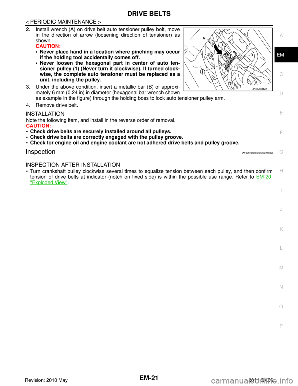
2. Install wrench (A) on drive belt auto tensioner pulley bolt, move
in the direction of arrow (loosening direction of tensioner) as
shown.
CAUTION:
Never place hand in a location where pinching may occurif the holding tool accidentally comes off.
Never loosen the hexagonal part in center of auto ten- sioner pulley (1) (Never turn it clockwise). If turned clock-
wise, the complete auto tensioner must be replaced as a
unit, including the pulley.
3. Under the above condition, insert a metallic bar (B) of approxi- mately 6 mm (0.24 in) in diameter (hexagonal bar wrench shown
as example in the figure) through the holding boss to lock auto tensioner pulley arm.
4. Remove drive belt.
INSTALLATION
Note the following item, and install in the reverse order of removal.
CAUTION:
Check drive belts are securely installed around all pulleys.
Check drive belts are correctly engaged with the pulley groove.
Check for engine oil and engine coolant ar e not adhered drive belts and pulley groove.
InspectionINFOID:0000000006289528
INSPECTION AFTER INSTALLATION
Turn crankshaft pulley clockwise several times to equalize tension between each pulley, and then confirm
tension of drive belts at indicator (notch on fixed side) is within the possible use range. Refer to EM-20,
"Exploded View".
JPBIA3484ZZ
Revision: 2010 May2011 QX56
Page 2596 of 5598

EM-34
< REMOVAL AND INSTALLATION >
ROCKER COVER
Loosen bolts in reverse order shown in the figure.
8. Remove rocker cover gasket from rocker cover.
9. Use scraper to remove all traces of liquid gasket from cylinder head & VVEL ladder assembly.
CAUTION:
Never scratch or damage the mating su rface when cleaning off old liquid gasket.
10. Remove PCV valve from rocker cover, if necessary.
11. Remove oil filler cap from rocker cover, if necessary.
INSTALLATION
1. Apply liquid gasket with the tube presser (commercial service tool) to VVEL ladder assembly (1).
Use Genuine RTV silicone seal ant or equivalent. Refer to
GI-22, "
Recommended Chemical Products and Sealants".
NOTE:
The figure shows an example of bank 1 side.
Apply liquid gasket on the front and rear side of engine first. [5 mm (0.20 in) + 5 mm (0.20 in) side as shown in the figure]
2. Install rocker cover gasket to rocker cover.
3. Install rocker cover. Check that rocker cover gasket does not drop fr om the installation groove of rocker cover.
A: Bank 2
B: Bank 1
: Engine front
JPBIA3481ZZ
A : Liquid gasket application point
F : End surface of VVEL ladder assembly
b : 4.0 mm (0.16 in)
c : 2.5 - 3.5 mm (0.098 - 0.138 in)
d : 5.0 mm (0.20 in)
e : 10.0 mm (0.39 in)
: Engine front
JPBIA3480ZZ
Revision: 2010 May2011 QX56
Page 2607 of 5598
HIGH PRESSURE FUEL PUMP AND FUEL HOSEEM-45
< REMOVAL AND INSTALLATION >
C
DE
F
G H
I
J
K L
M A
EM
NP
O
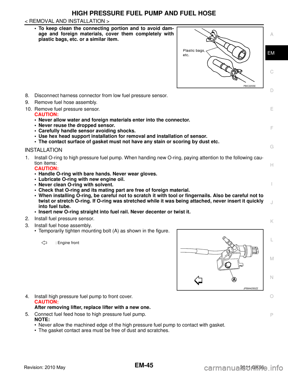
To keep clean the connecting portion and to avoid dam-
age and foreign materials, cover them completely with
plastic bags, etc. or a similar item.
8. Disconnect harness connector from low fuel pressure sensor.
9. Remove fuel hose assembly.
10. Remove fuel pressure sensor. CAUTION:
Never allow water and foreign mate rials enter into the connector.
Never reuse the dropped sensor.
Carefully handle sensor avoiding shocks.
Use hex head support installation fo r removal and installation of sensor.
The contact surface of gasket must not have any stain or scoring by dust etc.
INSTALLATION
1. Install O-ring to high pressure fuel pump. When handi ng new O-ring, paying attention to the following cau-
tion items:
CAUTION:
Handle O-ring with bare hands. Never wear gloves.
Lubricate O-ring with new engine oil.
Never clean O-ring with solvent.
Check that O-ring and its mating pa rt are free of foreign material.
When installing O-ring, be careful not to scratch it with tool or fingernails. Also be careful not to
twist or stretch O-ring. If O-ring was stretched wh ile it was being attached, never insert it quickly
into fuel tube.
Insert new O-ring straight into fu el rail. Never decenter or twist it.
2. Install fuel pressure sensor.
3. Install fuel hose assembly. Temporarily tighten mounting bolt (A) as shown in the figure.
4. Install high pressure fuel pump to front cover. CAUTION:
After removing lifter, replace lifter with a new one.
5. Connect fuel feed hose to high pressure fuel pump. NOTE:
Never allow the machined edge of the high pr essure fuel pump to contact with gasket.
The gasket contact area must be free of dust and scratches.
PBIC2205E
: Engine front
JPBIA4250ZZ
Revision: 2010 May2011 QX56
Page 2613 of 5598
![INFINITI QX56 2011 Factory Service Manual
FUEL INJECTOR AND FUEL TUBEEM-51
< REMOVAL AND INSTALLATION >
C
DE
F
G H
I
J
K L
M A
EM
NP
O
a. Install an injector seal drift set [SST: KV101197S0 (—)] (A) to
fuel injector (1).
b. Set seal ring INFINITI QX56 2011 Factory Service Manual
FUEL INJECTOR AND FUEL TUBEEM-51
< REMOVAL AND INSTALLATION >
C
DE
F
G H
I
J
K L
M A
EM
NP
O
a. Install an injector seal drift set [SST: KV101197S0 (—)] (A) to
fuel injector (1).
b. Set seal ring](/manual-img/42/57033/w960_57033-2612.png)
FUEL INJECTOR AND FUEL TUBEEM-51
< REMOVAL AND INSTALLATION >
C
DE
F
G H
I
J
K L
M A
EM
NP
O
a. Install an injector seal drift set [SST: KV101197S0 (—)] (A) to
fuel injector (1).
b. Set seal ring (1) to injector seal drift set [SST: KV101197S0 (—)]
(A).
c. Straightly insert seal ring (1), which is set in step 2, to fuel injec- tor as shown in the figure and install.
CAUTION:
Be careful that seal ring do es not exceed the groove portion
of fuel injector.
d. Insert injector seal drift set [SST: KV101197S0 (—)] (A) to injec- tor and rotate clockwise and counterclockwise by 90 ° while
pressing seal ring to fit it.
NOTE:
Compress seal ring, because this operation is for rectifying
stretch of seal ring caused by installation and for preventing
sticking when inserting injector into cylinder head.
2. Install O-ring and backup ring to fuel injector. When handing new O-ring and backup ring, paying attention to the following caution items:
CAUTION:
Handle O-ring with bare hands. Never wear gloves.
Lubricate O-ring with new engine oil.
Never clean O-ring with solvent.
Check that O-ring and its mating pa rt are free of foreign material.
When installing O-ring, be careful not to scratch it with tool or fingernails. Also be careful not to
twist or stretch O-ring. If O-ring was stretched wh ile it was being attached, never insert it quickly
into fuel tube.
Insert new O-ring straight into fu el rail. Never decenter or twist it.
JSBIA0347ZZ
JSBIA0348ZZ
JSBIA0350ZZ
JSBIA0351ZZ
Revision: 2010 May2011 QX56
Page 2615 of 5598
FUEL INJECTOR AND FUEL TUBEEM-53
< REMOVAL AND INSTALLATION >
C
DE
F
G H
I
J
K L
M A
EM
NP
O
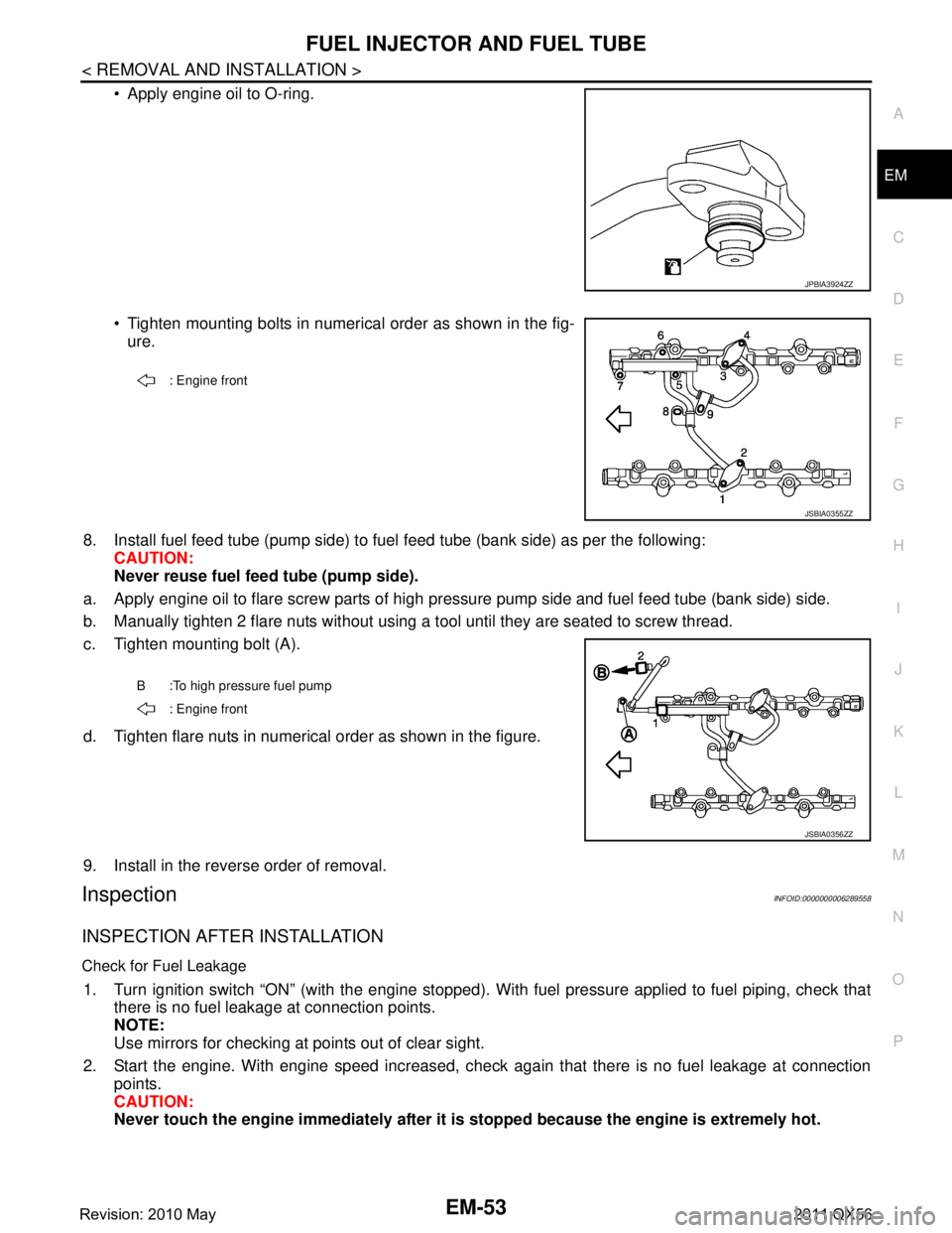
Apply engine oil to O-ring.
Tighten mounting bolts in numerical order as shown in the fig-
ure.
8. Install fuel feed tube (pump side) to fuel feed tube (bank side) as per the following:
CAUTION:
Never reuse fuel feed tube (pump side).
a. Apply engine oil to flare screw parts of high pr essure pump side and fuel feed tube (bank side) side.
b. Manually tighten 2 flare nuts without using a t ool until they are seated to screw thread.
c. Tighten mounting bolt (A).
d. Tighten flare nuts in numerical order as shown in the figure.
9. Install in the reverse order of removal.
InspectionINFOID:0000000006289558
INSPECTION AFTER INSTALLATION
Check for Fuel Leakage
1. Turn ignition switch “ON” (with the engine stopped). With fuel pressure applied to fuel piping, check that
there is no fuel leakage at connection points.
NOTE:
Use mirrors for checking at points out of clear sight.
2. Start the engine. With engine speed increased, check again that there is no fuel leakage at connection
points.
CAUTION:
Never touch the engine immediately after it is stopped because the engine is extremely hot.
JPBIA3924ZZ
: Engine front
JSBIA0355ZZ
B :To high pressure fuel pump
: Engine front
JSBIA0356ZZ
Revision: 2010 May2011 QX56
Page 2618 of 5598
EM-56
< REMOVAL AND INSTALLATION >
OIL PAN (LOWER) AND OIL STRAINER
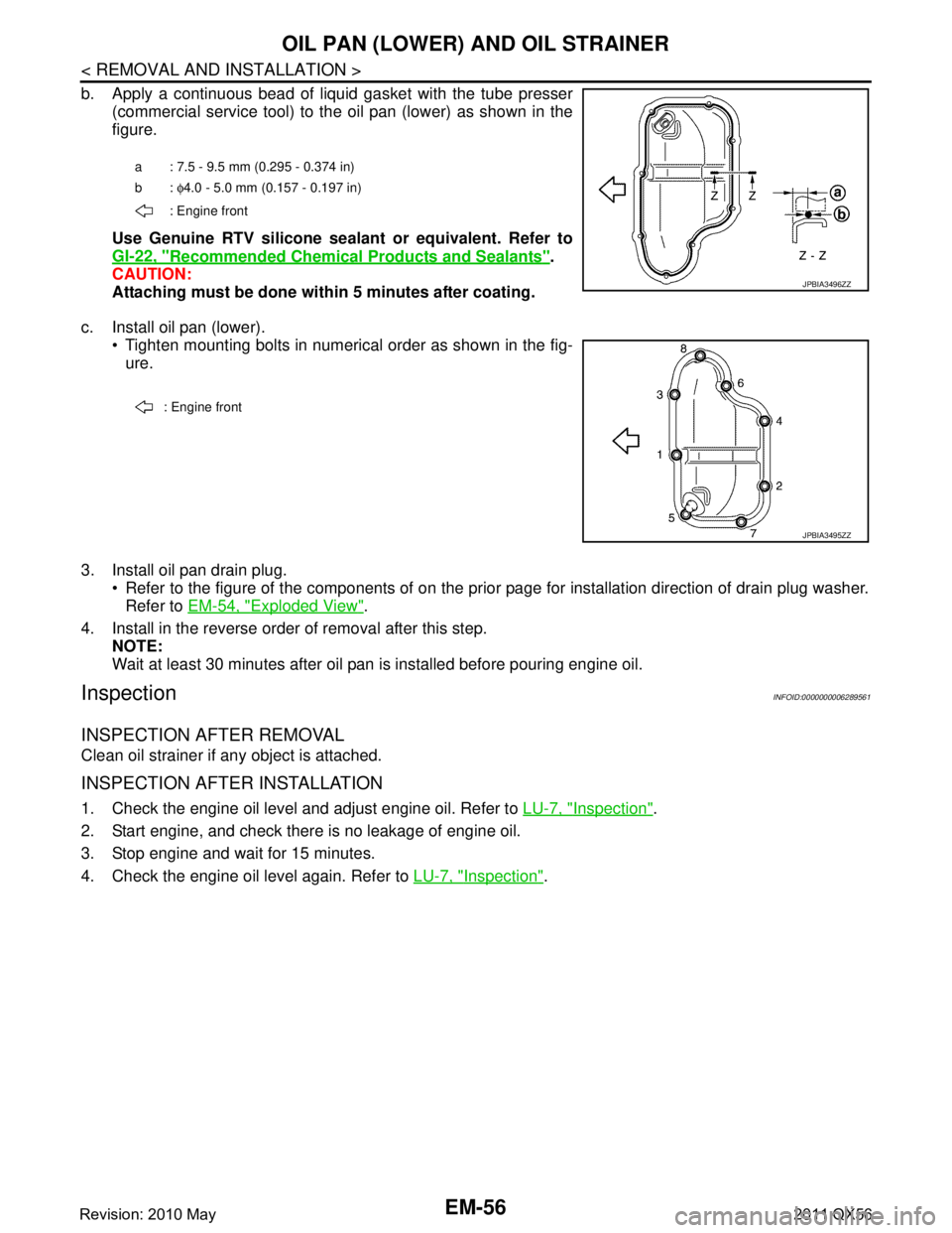
b. Apply a continuous bead of liquid gasket with the tube presser(commercial service tool) to the oil pan (lower) as shown in the
figure.
Use Genuine RTV silicone seal ant or equivalent. Refer to
GI-22, "
Recommended Chemical Products and Sealants".
CAUTION:
Attaching must be done with in 5 minutes after coating.
c. Install oil pan (lower). Tighten mounting bolts in numerical order as shown in the fig-ure.
3. Install oil pan drain plug. Refer to the figure of the components of on the prior page for installation direction of drain plug washer.Refer to EM-54, "
Exploded View".
4. Install in the reverse order of removal after this step. NOTE:
Wait at least 30 minutes after oil pan is installed before pouring engine oil.
InspectionINFOID:0000000006289561
INSPECTION AFTER REMOVAL
Clean oil strainer if any object is attached.
INSPECTION AFTER INSTALLATION
1. Check the engine oil level and adjust engine oil. Refer to LU-7, "Inspection".
2. Start engine, and check there is no leakage of engine oil.
3. Stop engine and wait for 15 minutes.
4. Check the engine oil level again. Refer to LU-7, "
Inspection".
a : 7.5 - 9.5 mm (0.295 - 0.374 in)
b: φ4.0 - 5.0 mm (0.157 - 0.197 in)
: Engine front
JPBIA3496ZZ
: Engine front
JPBIA3495ZZ
Revision: 2010 May2011 QX56
Page 2622 of 5598
EM-60
< REMOVAL AND INSTALLATION >
OIL PAN (UPPER)
3. Install oil pan (lower). Refer to EM-55, "Removal and Installation".
4. Install in the reverse order of removal. NOTE:
At least 30 minutes after oil pan is installed, pour engine oil.
InspectionINFOID:0000000006289564
INSPECTION AFTER DISASSEMBLY
Clean oil strainer if any object is attached.
INSPECTION AFTER ASSEMBLY
1. Check the engine oil level and adjust engine oil. Refer to LU-9, "Inspection".
2. Start engine, and check there is no leakage of engine oil.
3. Stop engine and wait for 15 minutes.
4. Check the engine oil level again. Refer to LU-9, "
Inspection".
Revision: 2010 May2011 QX56
Page 2631 of 5598
TIMING CHAINEM-69
< REMOVAL AND INSTALLATION >
C
DE
F
G H
I
J
K L
M A
EM
NP
O
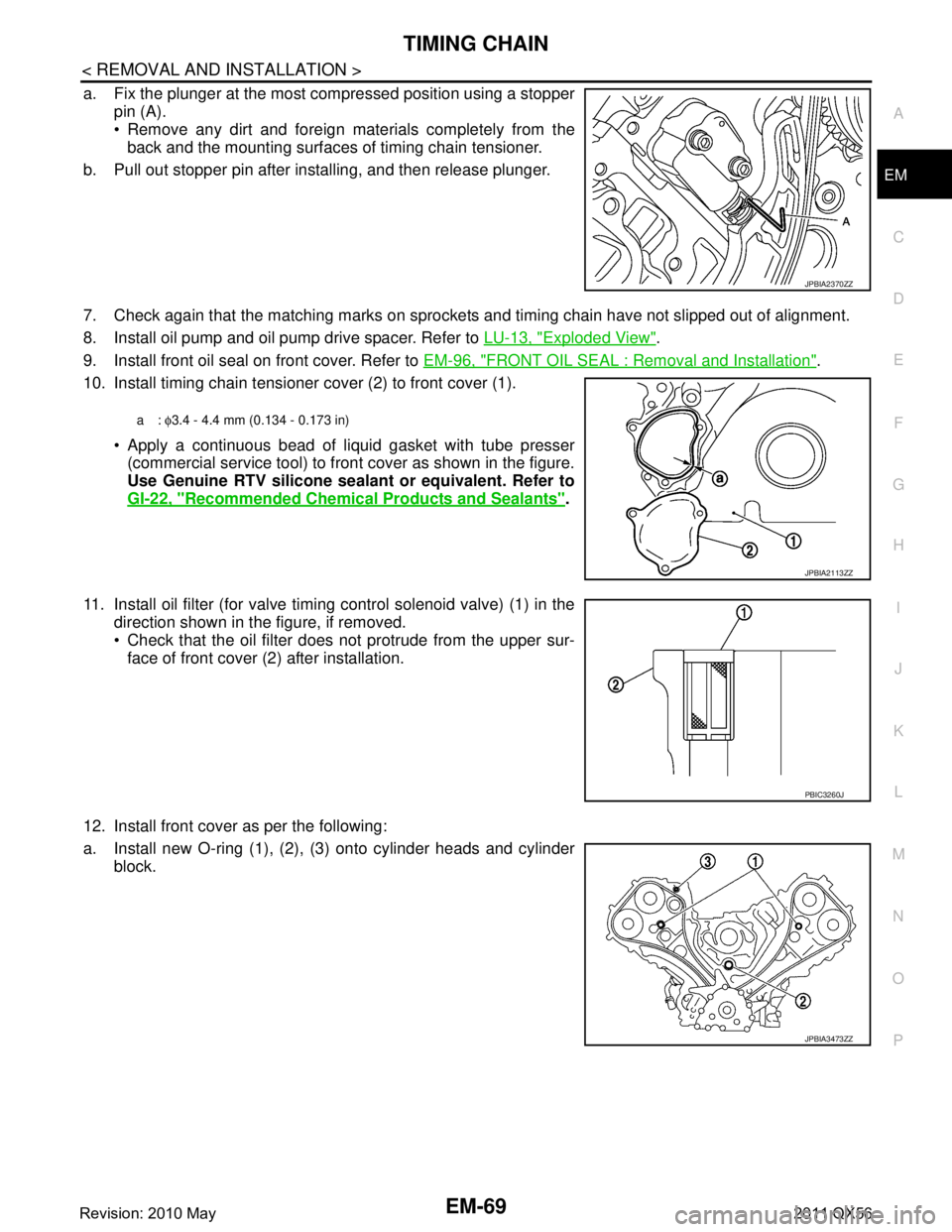
a. Fix the plunger at the most compressed position using a stopper
pin (A).
Remove any dirt and foreign materials completely from theback and the mounting surfaces of timing chain tensioner.
b. Pull out stopper pin after installing, and then release plunger.
7. Check again that the matching marks on sprockets and timing chain have not slipped out of alignment.
8. Install oil pump and oil pump drive spacer. Refer to LU-13, "
Exploded View".
9. Install front oil seal on front cover. Refer to EM-96, "
FRONT OIL SEAL : Removal and Installation".
10. Install timing chain tensioner cover (2) to front cover (1).
Apply a continuous bead of liquid gasket with tube presser(commercial service tool) to front cover as shown in the figure.
Use Genuine RTV silicone seal ant or equivalent. Refer to
GI-22, "
Recommended Chemical Products and Sealants".
11. Install oil filter (for valve timing control solenoid valve) (1) in the direction shown in the figure, if removed.
Check that the oil filter does not protrude from the upper sur-
face of front cover (2) after installation.
12. Install front cover as per the following:
a. Install new O-ring (1), (2), (3) onto cylinder heads and cylinder block.
JPBIA2370ZZ
a: φ3.4 - 4.4 mm (0.134 - 0.173 in)
JPBIA2113ZZ
PBIC3260J
JPBIA3473ZZ
Revision: 2010 May2011 QX56