2011 INFINITI QX56 oil level
[x] Cancel search: oil levelPage 3758 of 5598

MWI
SYSTEMMWI-15
< SYSTEM DESCRIPTION >
C
DE
F
G H
I
J
K L
M B A
O P
REFUEL CONTROL
The combination meter accelerates the fuel gauge if the all conditions listed below are met, or the ignition
switch is ON from OFF.
Ignition switch is ON position.
The vehicle is not moving.
The fuel level change by 15 (4 US gal, 3-1/4 Imp gal) or more.
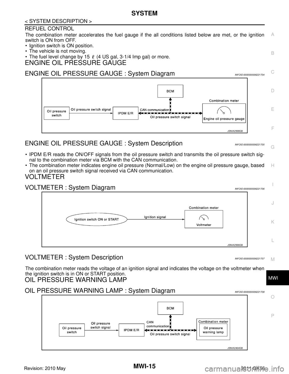
ENGINE OIL PRESSURE GAUGE
ENGINE OIL PRESSURE GAUGE : System DiagramINFOID:0000000006221704
ENGINE OIL PRESSURE GAUGE : System DescriptionINFOID:0000000006221705
IPDM E/R reads the ON/OFF signals from the oil pressure switch and transmits the oil pressure switch sig-
nal to the combination meter via BCM with the CAN communication.
The combination meter indicates engine oil pressure (Normal/Low) on the engine oil pressure gauge, based
on an oil pressure switch signal received via CAN communication.
VOLTMETER
VOLTMETER : System DiagramINFOID:0000000006221706
VOLTMETER : System DescriptionINFOID:0000000006221707
The combination meter reads the voltage of an ignition signal and indicates the voltage on the voltmeter when
the ignition switch is in ON or START position.
OIL PRESSURE WARNING LAMP
OIL PRESSURE WARNING LAMP : System DiagramINFOID:0000000006221708
JSNIA2998GB
JSNIA2996GB
JSNIA2464GB
Revision: 2010 May2011 QX56
Page 3761 of 5598

MWI-18
< SYSTEM DESCRIPTION >
SYSTEM
When recognizing an engine start, the combination meter controls the following items for producing the effect.
Speedometer
Tachometer
Engine coolant temperature gauge
Fuel gauge
Engine oil pressure gauge
Voltmeter
Meter illumination
Meter and Illumination Operations During Engine-start Effect
The combination meter controls the following items during the engine-start effect.
NOTE:
The pointers are stopped and illumination is turned off while cranking the engine.
Engine Start Judgement
The combination meter judges “engine-start” and activates the engine-start effect only once when the follow-
ing operational conditions are all satisfied.
NOTE:
Engine-start effect exits when any of the above operat ional conditions is cancelled during the engine-start
effect.
Signal path
The combination meter judges “engine-start,” according to the following signals and activates the engine-start
effect function.
DRIVER WELCOME FUNCTION
Control item Operation
Speedometer Sweeps the pointer.
Tachometer Sweeps the pointer.
Engine coolant temperature gauge Stops the pointer.
Fuel gauge Stops the pointer.
Engine oil pressure gauge Stops the pointer.
Voltmeter Stops the pointer.
Meter illumination Pointers Turns on the illumination at the effect level.
Information display Turns on the illumination at the normal brightness level.
Other than those above Increases the brightness to the effect level in stages.
Condition
Ignition switch ON position
Vehicle speed Less than 1 km/h (0.6 MPH)
Engine state Other than the time of cranking the engine
500 rpm or more
Information display
(SETTING) The setting of “EFFECT” is “ON.”
Signal name Signal path
Ignition signal —
Starter relay status signal BCM Combination meter
Engine speed signal ECM Combination meter
Engine status signal
Vehicle speed signal ABS actuator and electric unit (control unit) Combination meter
Revision: 2010 May2011 QX56
Page 3769 of 5598

MWI-26
< SYSTEM DESCRIPTION >
SYSTEM
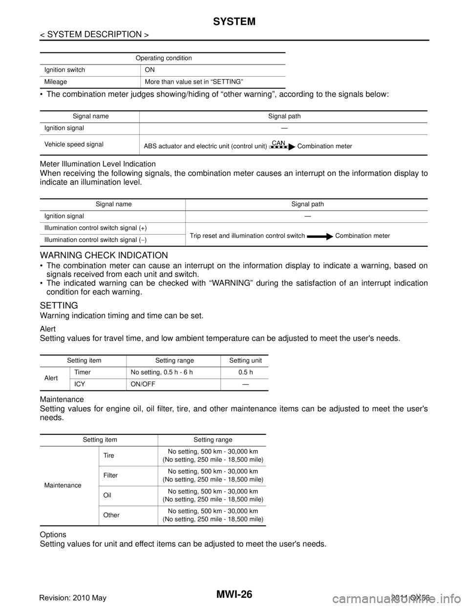
The combination meter judges showing/hiding of “other warning”, according to the signals below:
Meter Illumination Level Indication
When receiving the following signals, the combination meter causes an interrupt on the information display to
indicate an illumination level.
WARNING CHECK INDICATION
The combination meter can cause an interrupt on the information display to indicate a warning, based onsignals received from each unit and switch.
The indicated warning can be checked with “WARNING” during the satisfaction of an interrupt indication
condition for each warning.
SETTING
Warning indication timing and time can be set.
Alert
Setting values for travel time, and low ambient te mperature can be adjusted to meet the user's needs.
Maintenance
Setting values for engine oil, oil filter, tire, and other maintenance items can be adjusted to meet the user's
needs.
Options
Setting values for unit and effect items can be adjusted to meet the user's needs.
Operating condition
Ignition switch ON
Mileage More than value set in “SETTING”
Signal name Signal path
Ignition signal —
Vehicle speed signal ABS actuator and electric unit (control unit) Combination meter
Signal name Signal path
Ignition signal —
Illumination control switch signal (+) Trip reset and illumination control switch Combination meter
Illumination control switch signal ( −)
Setting item Setting range Setting unit
Alert Timer No setting, 0.5 h - 6 h 0.5 h
ICY ON/OFF —
Setting item Setting range
Maintenance Tire
No setting, 500 km - 30,000 km
(No setting, 250 mile - 18,500 mile)
Filter No setting, 500 km - 30,000 km
(No setting, 250 mile - 18,500 mile)
Oil No setting, 500 km - 30,000 km
(No setting, 250 mile - 18,500 mile)
Other No setting, 500 km - 30,000 km
(No setting, 250 mile - 18,500 mile)
Revision: 2010 May2011 QX56
Page 3774 of 5598
![INFINITI QX56 2011 Factory Service Manual
MWI
DIAGNOSIS SYSTEM (COMBINATION METER)
MWI-31
< SYSTEM DESCRIPTION >
C
D E
F
G H
I
J
K L
M B A
O P
W TEMP METER
[ ° C] XValue of engine coolant temperature signal is received from ECM via CAN com INFINITI QX56 2011 Factory Service Manual
MWI
DIAGNOSIS SYSTEM (COMBINATION METER)
MWI-31
< SYSTEM DESCRIPTION >
C
D E
F
G H
I
J
K L
M B A
O P
W TEMP METER
[ ° C] XValue of engine coolant temperature signal is received from ECM via CAN com](/manual-img/42/57033/w960_57033-3773.png)
MWI
DIAGNOSIS SYSTEM (COMBINATION METER)
MWI-31
< SYSTEM DESCRIPTION >
C
D E
F
G H
I
J
K L
M B A
O P
W TEMP METER
[ ° C] XValue of engine coolant temperature signal is received from ECM via CAN com-
munication.
NOTE:
215 is displayed when the malfunction signal is input.
ABS W/L
[On/Off] Status of ABS warning lamp detected fr
om ABS warning lamp signal is received
from ABS actuator and electric unit (control unit) via CAN communication.
VDC/TCS IND
[On/Off] Status of VDC OFF indicator lamp detected from VDC OFF indicator lamp signal
is received from ABS actuator
and electric unit (control unit) via CAN communica-
tion.
SLIP IND
[On/Off] Status of VDC warning lamp detected from VDC warning lamp signal received
from ABS actuator and electric unit (control unit) via CAN communication.
BRAKE W/L
[On/Off] Status of brake warning lamp detected from brake warning lamp signal is received
from ABS actuator and electric unit (control unit) via CAN communication.
NOTE:
Displays “Off” if the brake warning lamp is illuminated when the valve check starts,
the parking brake switch is turned ON or the brake fluid level switch is turned ON.
DOOR W/L
[On/Off] Status of door open warning detected from door switch signal received from BCM
via CAN communication.
HI-BEAM IND
[On/Off] Status of high beam indicator lamp detected from high beam request signal is re-
ceived from BCM via CAN communication.
TURN IND
[On/Off] Status of turn indicator lamp detected from turn indicator signal is received from
BCM via CAN communication.
FR FOG IND
[Off] This item is displayed, but cannot be monitored.
RR FOG IND
[Off] This item is displayed, but cannot be monitored.
LIGHT IND
[On/Off] Status of light indicator lamp detected from position light request signal is received
from BCM via CAN communication.
OIL W/L
[On/Off] Status of oil pressure warning lamp detected from oil pressure switch signal is re-
ceived from BCM via CAN communication.
MIL
[On/Off] Status of malfunction indicator lamp detected from malfunctioning indicator lamp
signal is received from ECM via CAN communication.
GLOW IND
[Off] This item is displayed, but cannot be monitored.
CRUISE IND
[On/Off] Status of CRUISE indicator detected from ASCD status signal is received from
ECM via CAN communicat ion. (ASCD models)
Status of CRUISE indicator de tected from meter display signal is received from
ADAS control unit via CAN communication. (ICC models)
SET IND
[On/Off] Status of SET indicator detected from meter display signal is received from ADAS
control unit via CAN communication.
CRUISE W/L
[On/Off] Status of CRUISE warning lamp
judged from ICC warning lamp signal received
from ADAS control unit with CAN communication line.
BA W/L
[On/Off] Status of IBA OFF indicator lamp judged from IBA OFF indicator lamp signal re-
ceived from ADAS control unit with CAN communication line.
ATC/T-AMT W/L
[On/Off] Status of A/T CHECK warning lamp judged
from A/T CHECK indicator lamp signal
received from TCM with CAN communication line.
ATF TEMP W/L
[Off] This item is displayed, but cannot be monitored.
4WD W/L
[On/Off] Status of 4WD warning lamp judged from 4WD warning lamp signal received from
4WD control unit with
CAN communication line.
FUEL W/L
[On/Off] Low-fuel warning lamp status detected by the identified fuel level.
WASHER W/L
[On/Off] Status of low washer fluid warning judged from washer level switch input to com-
bination meter.
Display item [Unit]
MAIN
SIGNALS Description
Revision: 2010 May2011 QX56
Page 3776 of 5598

MWI
DIAGNOSIS SYSTEM (COMBINATION METER)
MWI-33
< SYSTEM DESCRIPTION >
C
D E
F
G H
I
J
K L
M B A
O P
*: DDS (hill descent control) NOTE:
Some items are not available according to vehicle specification.
SPECIAL FUNCTION
Special menu
W/L ON HISTORY
Stores histories when warning/indicator lamp is turned on.
“W/L ON HISTORY” indicates the “TIME” when the warning/ indicator lamp is turned on.
The “TIME” above is:
- 0: The condition that the warning/indicator lamp has been turned on 1 or more times after starting the engine and waiting for 30 seconds.
- 1 - 39: The number of times the engine was restarted after the 0 condition.
- NO W/L ON HISTORY: Stores NO (0) turning on history of warning/indicator lamp.
NOTE:
W/L ON HISTORY is not stored for approximately 30 seconds after the engine starts.
Brake warning lamp does not store any history when the parking brake is applied or the brake fluid level gets
low.
Display Item
AT SFT DWN SW
[On/Off] Status of manual mode shift down switch.
PKB SW
[On/Off] Status of parking brake switch.
BUCKLE SW
[On/Off] Status of seat belt buckle switch (driver side).
BRAKE OIL SW
[On/Off] Status of brake fluid level switch.
A/C AMP CONN
[Off] This item is displayed, but cannot be monitored.
ENTER SW
[On/Off] Status of (ENTER) switch.
SELECT SW
[On/Off] Status of (SELECT) switch.
DISTANCE
[km] Value of distance to empty calculated by combination meter.
OUTSIDE TEMP
[ ° C or °F] Ambient temperature value converted from ambient sensor signal received from
ambient sensor.
NOTE:
This may not match with the temperature value indicated on the information dis-
play. (Because the information display value is a corrected value from the ambient
sensor input value.)
FUEL LOW SIG
[On/Off] Status of fuel level low warning signal to output to AV control unit via CAN com-
munication.
TOW MODE IND
[On/Off] Status of TOW mode indicator lamp judged from TOW mode indicator lamp signal
received from TCM with CAN communication line.
BUZZER
[On/Off] XBuzzer status (in the combination meter) is detected from the buzzer output signal
received from each unit via CAN communication and the warning output condition
of the combination meter.
Display item [Unit]
MAIN
SIGNALS Description
Display item Description
W/L ON HISTORY Lighting history of warning lamp and indicator lamp can be checked.
Revision: 2010 May2011 QX56
Page 3777 of 5598

MWI-34
< SYSTEM DESCRIPTION >
DIAGNOSIS SYSTEM (COMBINATION METER)
Display item Description
ABS W/L Lighting history of ABS warning lamp.
VDC/TCS IND Lighting history of VDC OFF indicator lamp.
SLIP IND Lighting history of VDC warning lamp.
BRAKE W/L Lighting history of brake warning lamp.
DOOR W/L Lighting history of door open warning.
TRUNK/GLAS-H This item is displa yed, but cannot be monitored.
OIL W/L Lighting history of oil pressure warning lamp.
C-ENG W/L Lighting history of malfunction indicator lamp.
C-ENG2 W/L This item is displayed, but cannot be monitored.
CRUISE IND Lighting history of CRUISE indicator lamp.
SET IND Lighting history of SET indicator lamp.
CRUISE W/L Lighting history of CRUISE warning lamp.
BA W/L Lighting history of IBA OFF indicator lamp.
O/D OFF IND This item is displayed, but cannot be monitored.
ATC/T-AMT W/L Lighting history of A/T CHECK warning lamp.
ATF TEMP W/L This item is displayed, but cannot be monitored.
CVT IND This item is displayed, but cannot be monitored.
SPORT IND This item is displayed, but cannot be monitored.
4WD W/L Lighting history of 4WD warning lamp.
FUEL W/L Lighting history of low fuel level warning.
WASHER W/L Lighting history of low washer fluid warning.
AIR PRES W/L Lighting history of low tire pressure warning lamp.
KEY G/Y W/L Lighting history of KEY warning lamp.
KEY R W/L This item is displaye d, but cannot be monitored.
KEY KNOB W/L This item is displa yed, but cannot be monitored.
EPS W/L This item is displayed, but cannot be monitored.
e-4WD This item is displayed, but cannot be monitored.
AFS OFF IND This item is displayed, but cannot be monitored.
4WAS/RAS W/L This item is displayed, but cannot be monitored.
HDC W/L This item is displayed, but cannot be monitored.
SYS FAIL W/L This item is displa yed, but cannot be monitored.
SFT POSI W/L This item is displayed, but cannot be monitored.
HV BAT W/L This item is displayed, but cannot be monitored.
HEV BRAKE W/L This item is displayed, but cannot be monitored.
SFT OPER W/L This item is displayed, but cannot be monitored.
LANE W/L Lighting history of lane departure warning lamp.
CHAGE W/L This item is displayed, but cannot be monitored.
OIL LEV LOW This item is displayed, but cannot be monitored.
DPF W/L This item is displayed, but cannot be monitored.
TRAILER IND This item is displayed, but cannot be monitored.
RUN FLAT W/L This item is displa yed, but cannot be monitored.
E-SUS W/L This item is displayed, but cannot be monitored.
LAUNCH CNT W/L This item is displayed, but cannot be monitored.
BRAKE PAD W/L This item is displa yed, but cannot be monitored.
Revision: 2010 May2011 QX56
Page 3781 of 5598

MWI-38
< ECU DIAGNOSIS INFORMATION >
COMBINATION METER
SHIFT INDIgnition switch
ONDuring the indication of “P” by shift position
indicator
P
During the indication of “R” by shift position
indicator R
During the indication of “N” by shift position
indicator N
During the indication of “D” by shift position
indicator D
During the indication of “M1” by shift posi-
tion indicator M1
During the indication of “M2” by shift posi-
tion indicator M2
During the indication of “M3” by shift posi-
tion indicator M3
During the indication of “M4” by shift posi-
tion indicator M4
During the indication of “M5” by shift posi-
tion indicator M5
During the indication of “M6” by shift posi-
tion indicator M6
During the indication of “M7” by shift posi-
tion indicator M7
4WD IND Ignition switch
ON4WD shift switch in AUTO position AUTO
4WD shift switch in 4H position LOCK
4WD shift switch in 4L position LOCK/4Lo
BSW IND Ignition switch
ONNOTE:
This item is displayed, but cannot be moni-
tored.
Off
BSW W/L Ignition switch
ONBSW warning lamp ON On
BSW warning lamp OFF Off
AT S MODE SW Ignition switch
ONSnow mode switch ON On
Snow mode switch OFF Off
M RANGE SW Ignition switch
ONSelector lever in manual mode position On
Other than the above Off
NM RANGE SW Ignition switch
ONSelector lever in manual mode position Off
Other than the above On
AT SFT UP SW Ignition switch
ONSelector lever in + position On
Other than the above Off
AT SFT DWN SW Ignition switch
ONSelector lever in – position On
Other than the above Off
PKB SW Ignition switch
ONParking brake switch ON On
Parking brake switch OFF Off
BUCKLE SW Ignition switch
ONDriver seat belt not fastened On
Driver seat belt fastened Off
BRAKE OIL SW Ignition switch
ONBrake fluid level switch ON On
Brake fluid level switch OFF Off
A/C AMP CONN Ignition switch
ONNOTE:
This item is displayed, but cannot be moni-
tored.
Off
Monitor Item Condition Value/Status
Revision: 2010 May2011 QX56
Page 4260 of 5598

REAR SUSPENSION ASSEMBLYRSU-5
< PERIODIC MAINTENANCE >
C
DF
G H
I
J
K L
M A
B
RSU
N
O P
PERIODIC MAINTENANCE
REAR SUSPENSION ASSEMBLY
InspectionINFOID:0000000006225660
MOUNTING INSPECTION
Check the mounting conditions (looseness, backlash) of each component and component conditions (wear,
damage) are normal.
BALL JOINT AXIAL END PLAY
Measure axial end play by placing and moving up/down with an iron bar or equivalent between suspension
arm or front lower link and axle assembly.
CAUTION:
• Never depress brake pedal when measuring.
Never perform with tires on level ground.
Be careful not to damage ball joint boot.
SHOCK ABSORBER
Check for oil leakage and damage. Replace it if necessary. Axial end play : Refer to
RSU-20, "
Ball Joint".
Revision: 2010 May2011 QX56