2011 INFINITI QX56 oil level
[x] Cancel search: oil levelPage 2992 of 5598
GI-28
< PRECAUTION >
PRECAUTIONS
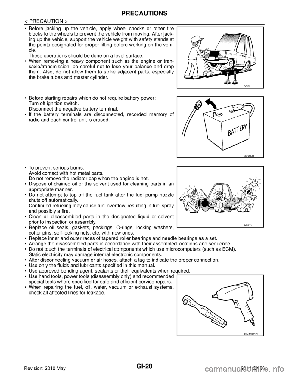
Before jacking up the vehicle, apply wheel chocks or other tireblocks to the wheels to prevent t he vehicle from moving. After jack-
ing up the vehicle, support the vehicle weight with safety stands at
the points designated for proper lifting before working on the vehi-
cle.
These operations should be done on a level surface.
When removing a heavy component such as the engine or tran- saxle/transmission, be careful not to lose your balance and drop
them. Also, do not allow them to strike adjacent parts, especially
the brake tubes and master cylinder.
Before starting repairs which do not require battery power: Turn off ignition switch.
Disconnect the negative battery terminal.
If the battery terminals are disconnected, recorded memory of
radio and each control unit is erased.
To prevent serious burns: Avoid contact with hot metal parts.
Do not remove the radiator cap when the engine is hot.
Dispose of drained oil or the solvent used for cleaning parts in an appropriate manner.
Do not attempt to top off the fuel tank after the fuel pump nozzle
shuts off automatically.
Continued refueling may cause fuel overflow, resulting in fuel spray
and possibly a fire.
Clean all disassembled parts in the designated liquid or solvent prior to inspection or assembly.
Replace oil seals, gaskets, packings, O-rings, locking washers,
cotter pins, self-locking nuts, etc. with new ones.
Replace inner and outer races of tapered roller bearings and needle bearings as a set.
Arrange the disassembled parts in accordance with their assembled locations and sequence.
Do not touch the terminals of electrical com ponents which use microcomputers (such as ECM).
Static electricity may damage internal electronic components.
After disconnecting vacuum or air hoses, atta ch a tag to indicate the proper connection.
Use only the fluids and lubricants specified in this manual.
Use approved bonding agent, sealants or their equivalents when required.
Use hand tools, power tools (disassembly only) and recommended special tools where specified for safe and efficient service repairs.
When repairing the fuel, oil, water, vacuum or exhaust systems, check all affected lines for leakage.
SGI231
SEF289H
SGI233
JPAIA0335ZZ
Revision: 2010 May2011 QX56
Page 3029 of 5598
INSPECTION AND ADJUSTMENTGI-65
< BASIC INSPECTION >
C
DE
F
G H
I
J
K L
M B
GI
N
O PINSPECTION AND ADJUSTMENT
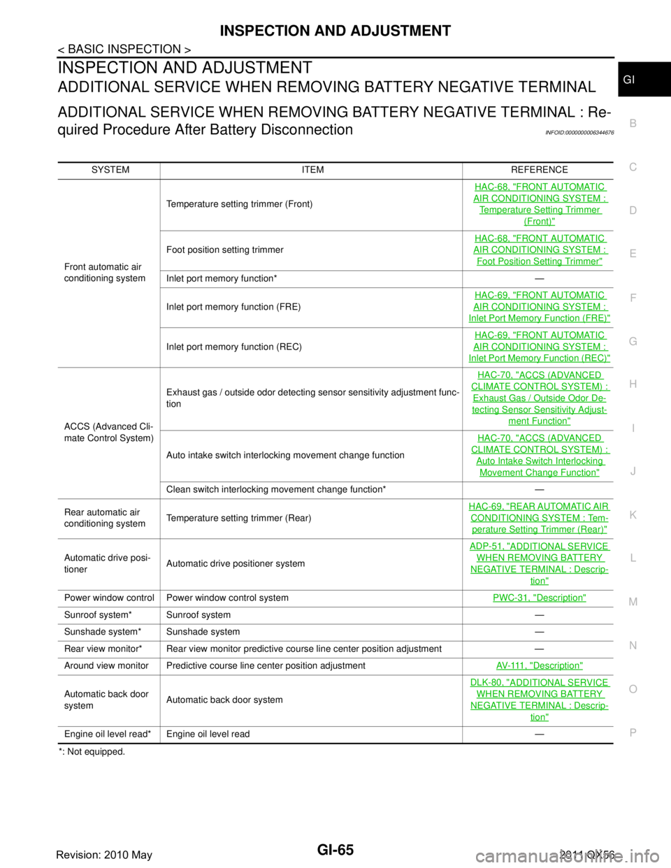
ADDITIONAL SERVICE WHEN REMOVING BATTERY NEGATIVE TERMINAL
ADDITIONAL SERVICE WHEN REMOVING BATTERY NEGATIVE TERMINAL : Re-
quired Procedure After Battery Disconnection
INFOID:0000000006344676
*: Not equipped. SYSTEM ITEM REFERENCE
Front automatic air
conditioning system Temperature setting trimmer (Front)
HAC-68, "
FRONT AUTOMATIC
AIR CONDITIONING SYSTEM :
Temperature Setting Trimmer
(Front)"
Foot position setting trimmer
HAC-68, "
FRONT AUTOMATIC
AIR CONDITIONING SYSTEM :
Foot Position Setting Trimmer"
Inlet port memory function* —
Inlet port memory function (FRE)
HAC-69, "
FRONT AUTOMATIC
AIR CONDITIONING SYSTEM :
Inlet Port Memory
Function (FRE)"
Inlet port memory function (REC) HAC-69, "
FRONT AUTOMATIC
AIR CONDITIONING SYSTEM :
Inlet Port Memory Function (REC)"
ACCS (Advanced Cli-
mate Control System)Exhaust gas / outside odor detecting sensor sensitivity adjustment func-
tion
HAC-70, "
ACCS (ADVANCED
CLIMATE CONTROL SYSTEM) :
Exhaust Gas / Outside Odor De-
tecting Sensor Sensitivity Adjust-
ment Function"
Auto intake switch interlocking movement change function
HAC-70, "
ACCS (ADVANCED
CLIMATE CONTROL SYSTEM) :
Auto Intake Switch Interlocking
Movement Change Function"
Clean switch interlocking movement change function* —
Rear automatic air
conditioning system Temperature setting trimmer (Rear) HAC-69, "
REAR AUTOMATIC AIR
CONDITIONING SYSTEM : Tem-
perature Setting
Trimmer (Rear)"
Automatic drive posi-
tioner Automatic drive positioner system ADP-51, "
ADDITIONAL SERVICE
WHEN REMOVING BATTERY
NEGATIVE TERMINAL : Descrip-
tion"
Power window control Power window control system
PWC-31, "Description"
Sunroof system* Sunroof system —
Sunshade system* Sunshade system —
Rear view monitor* Rear view monitor predictive course line center position adjustment —
Around view monitor Predictive course line center position adjustment AV- 111 , "
Description"
Automatic back door
systemAutomatic back door system DLK-80, "
ADDITIONAL SERVICE
WHEN REMOVING BATTERY
NEGATIVE TERMINAL : Descrip-
tion"
Engine oil level read* Engine oil level read —
Revision: 2010 May2011 QX56
Page 3061 of 5598
PRECAUTIONSHA-5
< PRECAUTION >
C
DE
F
G H
J
K L
M A
B
HA
N
O P
- Never allow lubricant (A/C System Oil Type R) to come in contact with styrene foam parts. Damage
may result.
REFRIGERANT CONNECTION
A new type refrigerant connection has been introduced to a ll refrigerant lines except the following location.
Expansion valve to evaporator
Refrigerant pressure sensor to liquid tank
WARNING:
Check that all refrigerant is discharged into the recycling equipment and the pressure in the system is
less than atmospheric pressure. Then gradually loo sen the discharge side hose fitting and remove it.
CAUTION:
Observe the following when replacing or cleaning refrigerant cycle components.
Store it in the same way at it is when mounted on the car when the compressor is removed. Failure
to do so will cause lubricant to enter the low-pressure chamber.
Use always a torque wrench and a b ack-up wrench when connecting tubes.
Plug immediately all openings to prevent entry of dust and mois ture after disconnecting tubes.
Connect the pipes at the final stag e of the operation when installing an air conditioner in the vehicle.
Never remove the seal caps of pipes and other compon ents until just before required for connection.
Allow components stored in cool areas to warm to working area temperature before removing seal
caps. This prevents condensation from forming inside A/C components.
Remove thoroughly moisture from the refriger ation system before charging the refrigerant.
Replace always used O-rings.
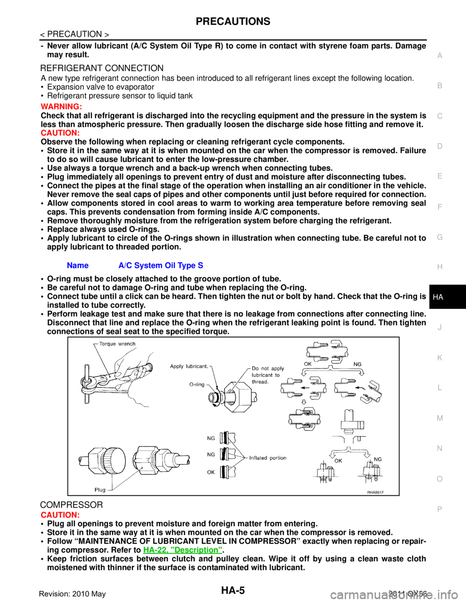
Apply lubricant to circle of th e O-rings shown in illustration when connecting tube. Be careful not to
apply lubricant to threaded portion.
O-ring must be closely attached to the groove portion of tube.
Be careful not to damage O-ring and tube when replacing the O-ring.
Connect tube until a click can be heard. Then tighten the nut or bolt by hand. Check that the O-ring is
installed to tube correctly.
Perform leakage test and make sure that there is no leakage from connections after connecting line.
Disconnect that line and replace the O-ring when the refrigerant leaking point is found. Then tighten
connections of seal seat to the specified torque.
COMPRESSOR
CAUTION:
Plug all openings to prevent moisture and foreign matter from entering.
Store it in the same way at it is when moun ted on the car when the compressor is removed.
Follow “MAINTENANCE OF LUBRICANT LEVEL IN CO MPRESSOR” exactly when replacing or repair-
ing compressor. Refer to HA-22, "
Description".
Keep friction surfaces between clutch and pulley cl ean. Wipe it off by using a clean waste cloth
moistened with thinner if the surface is contaminated with lubricant.
Name A/C System Oil Type S
RHA861F
Revision: 2010 May2011 QX56
Page 3078 of 5598
HA-22
< BASIC INSPECTION >
LUBRICANT
LUBRICANT
DescriptionINFOID:0000000006276153
MAINTENANCE OF LUBRICANT LEVEL
The compressor lubricant is circulating in the system together with the refrigerant. It is necessary to fill com-
pressor with lubricant when replacing A/C system pa rts or when a large amount of refrigerant leakage is
detected. It is important to always maintain lubricant level within the specified level. Otherwise, the following
conditions may occur.
Insufficient lubricant amount: Stuck compressor
Excessive lubricant amount: Insufficient cooling (caused by insufficient heat exchange)
InspectionINFOID:0000000006276154
If a compressor is malfunctioning (internal noise, insufficient cooling), check the compressor oil.
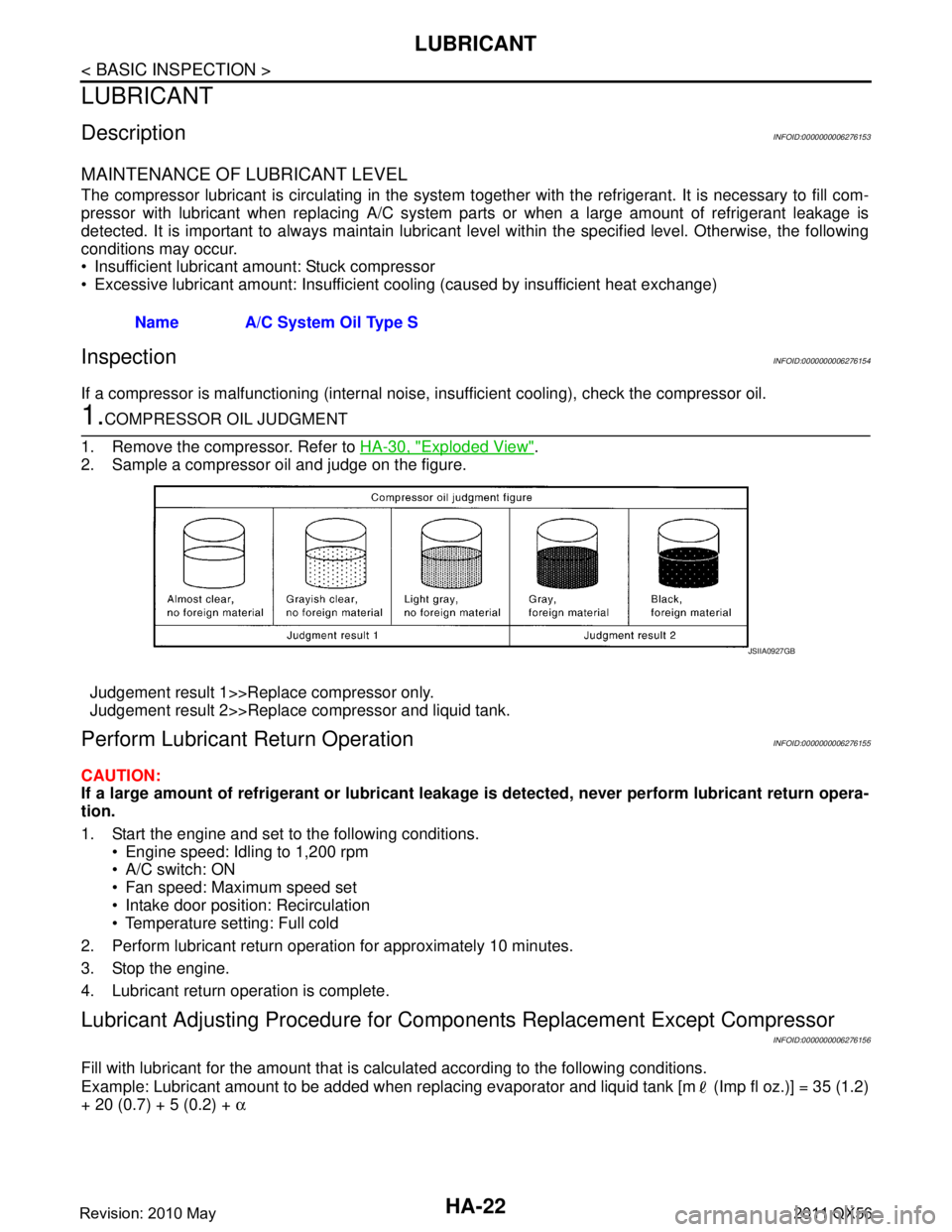
1.COMPRESSOR OIL JUDGMENT
1. Remove the compressor. Refer to HA-30, "
Exploded View".
2. Sample a compressor oil and judge on the figure.
Judgement result 1>>Replace compressor only.
Judgement result 2>>Replace compressor and liquid tank.
Perform Lubricant Return OperationINFOID:0000000006276155
CAUTION:
If a large amount of refrigerant or lubricant leakag e is detected, never perform lubricant return opera-
tion.
1. Start the engine and set to the following conditions.
Engine speed: Idling to 1,200 rpm
A/C switch: ON
Fan speed: Maximum speed set
Intake door position: Recirculation
Temperature setting: Full cold
2. Perform lubricant return operation for approximately 10 minutes.
3. Stop the engine.
4. Lubricant return operation is complete.
Lubricant Adjusting Procedure for Comp onents Replacement Except Compressor
INFOID:0000000006276156
Fill with lubricant for the amount that is calculated according to the following conditions.
Example: Lubricant amount to be added when replacing evapor ator and liquid tank [m (Imp fl oz.)] = 35 (1.2)
+ 20 (0.7) + 5 (0.2) + α
Name A/C System Oil Type S
JSIIA0927GB
Revision: 2010 May2011 QX56
Page 3088 of 5598
HA-32
< REMOVAL AND INSTALLATION >
COMPRESSOR
2. Remove center bolt, and then remove clutch disc.
3. Remove snap ring using external snap ring pliers.
4. Position center pulley puller on the end of the drive shaft, and remove pulley assembly using any commer-
cially available pulley puller.
To prevent pulley groove from being deformed, pulle r claws should be positioned into the edge of the pul-
ley assembly.
5. Disconnect field coil harness from compressor unit.
6. Remove screws, and then remove field coil.
INSTALLATION
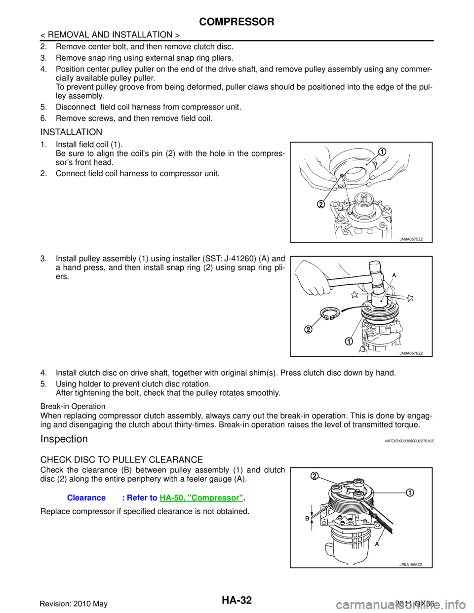
1. Install field coil (1). Be sure to align the coil’s pin (2) with the hole in the compres-
sor’s front head.
2. Connect field coil harness to compressor unit.
3. Install pulley assembly (1) using installer (SST: J-41260) (A) and a hand press, and then install snap ring (2) using snap ring pli-
ers.
4. Install clutch disc on drive shaft, together with original shim(s). Press clutch disc down by hand.
5. Using holder to prevent clutch disc rotation. After tightening the bolt, check that the pulley rotates smoothly.
Break-in Operation
When replacing compressor clutch assembly, always carry out the break-in operation. This is done by engag-
ing and disengaging the clutch about thirty-times. Break-i n operation raises the level of transmitted torque.
InspectionINFOID:0000000006276165
CHECK DISC TO PULLEY CLEARANCE
Check the clearance (B) between pulley assembly (1) and clutch
disc (2) along the entire periphery with a feeler gauge (A).
Replace compressor if specified clearance is not obtained.
JMIIA0575ZZ
JMIIA0576ZZ
Clearance : Refer to HA-50, "Compressor".
JPIIA1566ZZ
Revision: 2010 May2011 QX56
Page 3451 of 5598
![INFINITI QX56 2011 Factory Service Manual
LAN
SYSTEMLAN-31
< SYSTEM DESCRIPTION > [CAN]
C
D
E
F
G H
I
J
K L
B A
O P
N
Meter display signal
TR
RT
Oil pressure switch signal TR
RT
Position light request signal T R R
Rear fog light status signa INFINITI QX56 2011 Factory Service Manual
LAN
SYSTEMLAN-31
< SYSTEM DESCRIPTION > [CAN]
C
D
E
F
G H
I
J
K L
B A
O P
N
Meter display signal
TR
RT
Oil pressure switch signal TR
RT
Position light request signal T R R
Rear fog light status signa](/manual-img/42/57033/w960_57033-3450.png)
LAN
SYSTEMLAN-31
< SYSTEM DESCRIPTION > [CAN]
C
D
E
F
G H
I
J
K L
B A
O P
N
Meter display signal
TR
RT
Oil pressure switch signal TR
RT
Position light request signal T R R
Rear fog light status signal T R
Rear window defogger con-
trol signal TR
RT
Sleep wake up signal T R R R R R R
Starter control relay signal T R
Starter relay status signal TRR
RT
Starting mode signal T R
Steering lock relay signal TRR
RT
Theft warning horn request
signal TR
Turn indicator signal R T R R
A/C display signal R T
A/C ON signal R T
Ambient temperature signal T R
Blower fan ON signal R T
Distance to empty signal R T
Fuel level low warning sig-
nal RT
Fuel level sensor signal R T
Manual mode shift down
signal RT
Manual mode shift up sig-
nal RT
Manual mode signal R T
Non-manual mode signal R T
Odometer signal R T
Parking brake switch signal R R T R R
Sleep-ready signal RT
RT
RT
Tow mode switch signal R T
Wake up signal RT
RT
Steering angle sensor mal-
function signal RR T R R
Steering angle sensor sig-
nal RR RR T R R
Steering angle speed signal R T R R Signal name
ECM
4WD
ABS
TCM
A-BAG AFS
AV
BCM
CGW
HVAC M&A
STRG
TPMS
IPDM-E
ADPPSB
E-SUS ICC
PWBD
Revision: 2010 May2011 QX56
Page 3660 of 5598
ENGINE OILLU-7
< PERIODIC MAINTENANCE >
C
DE
F
G H
I
J
K L
M A
LU
NP
O
PERIODIC MAINTENANCE
ENGINE OIL
InspectionINFOID:0000000006289616
OIL LEVEL
NOTE:
Before starting engine, put vehicle horizontally and check
the engine oil level. If engine is already started, stop
it and allow 10 minutes before checking.
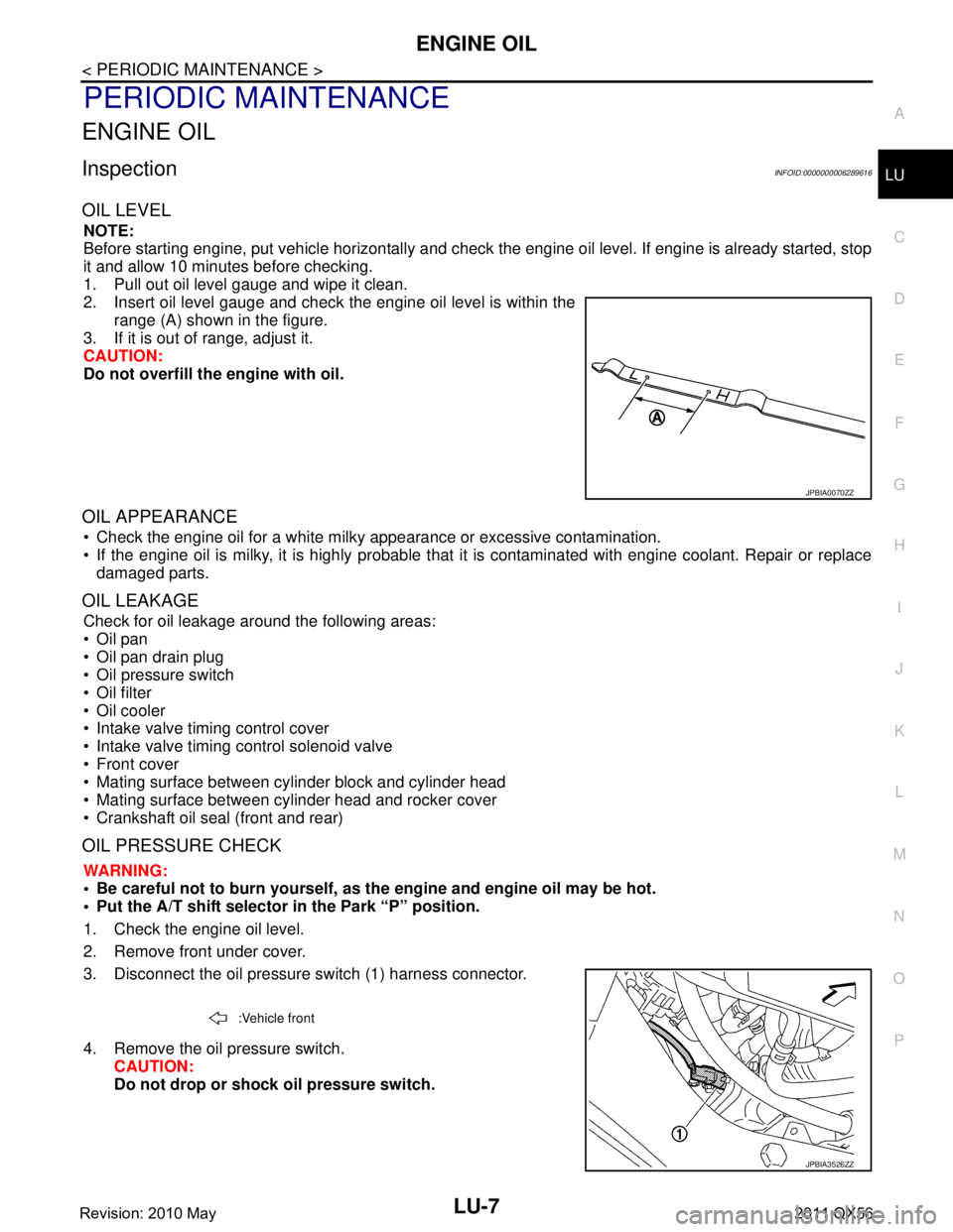
1. Pull out oil level gauge and wipe it clean.
2. Insert oil level gauge and check the engine oil level is within the range (A) shown in the figure.
3. If it is out of range, adjust it.
CAUTION:
Do not overfill the engine with oil.
OIL APPEARANCE
Check the engine oil for a white milky appearance or excessive contamination.
If the engine oil is milky, it is highly probable that it is contaminated with engine coolant. Repair or replace
damaged parts.
OIL LEAKAGE
Check for oil leakage around the following areas:
Oil pan
Oil pan drain plug
Oil pressure switch
Oil filter
Oil cooler
Intake valve timing control cover
Intake valve timing control solenoid valve
Front cover
Mating surface between cylinder block and cylinder head
Mating surface between cylinder head and rocker cover
Crankshaft oil seal (front and rear)
OIL PRESSURE CHECK
WARNING:
• Be careful not to burn yourself, as th e engine and engine oil may be hot.
Put the A/T shift selector in the Park “P” position.
1. Check the engine oil level.
2. Remove front under cover.
3. Disconnect the oil pressure switch (1) harness connector.
4. Remove the oil pressure switch. CAUTION:
Do not drop or shock oil pressure switch.
JPBIA0070ZZ
:Vehicle front
JPBIA3526ZZ
Revision: 2010 May2011 QX56
Page 3661 of 5598
![INFINITI QX56 2011 Factory Service Manual
LU-8
< PERIODIC MAINTENANCE >
ENGINE OIL
5. Install the oil pressure gauge [SST: ST25051001 (J25695-1)] (A)and hose [SST: ST25052000 (J25695-2)] (B).
6. Start the engine and warm it up to normal oper INFINITI QX56 2011 Factory Service Manual
LU-8
< PERIODIC MAINTENANCE >
ENGINE OIL
5. Install the oil pressure gauge [SST: ST25051001 (J25695-1)] (A)and hose [SST: ST25052000 (J25695-2)] (B).
6. Start the engine and warm it up to normal oper](/manual-img/42/57033/w960_57033-3660.png)
LU-8
< PERIODIC MAINTENANCE >
ENGINE OIL
5. Install the oil pressure gauge [SST: ST25051001 (J25695-1)] (A)and hose [SST: ST25052000 (J25695-2)] (B).
6. Start the engine and warm it up to normal operating temperature.
7. Check the engine oil pressure with engine running under no-load. Refer to LU-17, "
EngineOilPressure".
CAUTION:
If the difference is extreme, check the oil passages and oil pump for leaks and blockages.
8. After the inspections, install oil pressure switch as follows:
a. Remove old liquid gasket adhering to oil pressure switch and engine.
b. Apply liquid gasket and tighten oil pressure switch to the specification. Use Genuine RTV Silicone Seal ant or equivalent. Refer to GI-22, "
Recommended Chemical Prod-
ucts and Sealants".
c. After warming up engine, make sure there is no leakage of engine oil with engine running.
DrainingINFOID:0000000006289617
WARNING:
Be careful not to burn yourself, as th e engine and engine oil may be hot.
Prolonged and repeated contact with used engine oil may cause skin cancer; try to avoid direct skin
contact with used oil. If skin contact is made, wash thoroughly with soap or hand cleaner as soon as
possible.
1. Warm up the engine, and check for any oil leaks.
2. Stop the engine and wait for at least 10 minutes.
3. Remove drain plug and oil filler cap to drain the old oil.
RefillingINFOID:0000000006289618
1. Install drain plug with new washer. CAUTION:
Be sure to clean drain plug and install with new washer.
2. Refill with new engine oil. Engine oil specification and viscosity:
Refer to MA-10, "
Fluids and Lubricants".
CAUTION:
The refill capacity depends on the engine oi l temperature and drain time. Use these specifica-
tions for reference only.
Always use oil level gauge to determine the proper amount of engine oil in engine.
3. Warm up the engine and check area around drain plug and oil filter for engine oil leakage.
4. Stop the engine and wait for 10 minutes.
5. Check the engine oil level. Refer to LU-7, "
Inspection".
JPBIA0074ZZ
Oil pressure switch torque : Refer to EM-57, "Exploded View".
Tightening torque : Refer to EM-54, "
Exploded View".
Engine oil capacity : Refer to LU-17, "
Periodical Maintenance Specification".
Revision: 2010 May2011 QX56