2011 INFINITI QX56 oil level
[x] Cancel search: oil levelPage 2657 of 5598

CYLINDER HEADEM-95
< REMOVAL AND INSTALLATION >
C
DE
F
G H
I
J
K L
M A
EM
NP
O
If hydraulic pressure inside chain tensioner drops after removal/installation, slack in guide may generate a
pounding noise during and just after the engine start. However, this does not indicate a malfunction. The
noise will stop after hydraulic pressure rises.
Warm up engine thoroughly to check that there is no leak age of fuel, or any oil/fluids including engine oil and
engine coolant.
Bleed air from lines and hoses of applicable lines, such as in cooling system.
After cooling down engine, again check oil/fluid levels including engine oil and engine coolant. Refill them to
the specified level, if necessary.
Summary of the inspection items:
* Power steering fluid, brake fluid, etc. Items Before starting engine Engine running After engine stopped
Engine coolant Level Leakage Level
Engine oil Level Leakage Level
Transmission /
transaxle fluid AT & CVT Models Leakage Level / Leakage Leakage
MT Models Level / Leakage Leakage Level / Leakage
Other oils and fluids* Level Leakage Level
Fuel Leakage Leakage Leakage
Revision: 2010 May2011 QX56
Page 2659 of 5598
OIL SEALEM-97
< REMOVAL AND INSTALLATION >
C
DE
F
G H
I
J
K L
M A
EM
NP
O
REAR OIL SEAL : Removal and InstallationINFOID:0000000006289575
REMOVAL
1. Remove transmission assembly. Refer to
TM-205, "2WD : Exploded View" (2WD models) or TM-208,
"4WD : Exploded View" (4WD models).
2. Remove drive plate. Refer to EM-106, "
Exploded View".
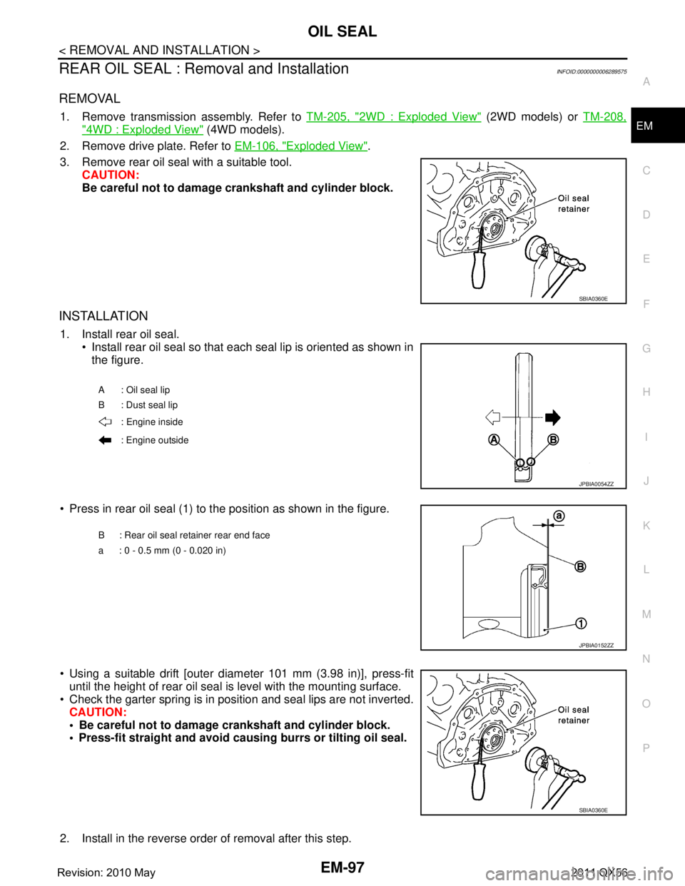
3. Remove rear oil seal with a suitable tool. CAUTION:
Be careful not to damage crankshaft and cylinder block.
INSTALLATION
1. Install rear oil seal. Install rear oil seal so that each seal lip is oriented as shown in
the figure.
Press in rear oil seal (1) to the position as shown in the figure.
Using a suitable drift [outer diameter 101 mm (3.98 in)], press-fit until the height of rear oil seal is level with the mounting surface.
Check the garter spring is in position and seal lips are not inverted. CAUTION:
Be careful not to damage crankshaft and cylinder block.
Press-fit straight and avoid cau sing burrs or tilting oil seal.
2. Install in the reverse order of removal after this step.
SBIA0360E
A : Oil seal lip
B : Dust seal lip : Engine inside
: Engine outside
JPBIA0054ZZ
B : Rear oil seal retainer rear end face
a : 0 - 0.5 mm (0 - 0.020 in)
JPBIA0152ZZ
SBIA0360E
Revision: 2010 May2011 QX56
Page 2664 of 5598
EM-102
< UNIT REMOVAL AND INSTALLATION >
ENGINE ASSEMBLY
INSTALLATION
Install in the reverse order of removal.
CAUTION:
When replacing an engine or transmission you must make sure the dowels are installed correctly
during re-assembly.Improper alignment caused by mi ssing dowels may cause vibration, oil leaks or
breakage of drivetrain components.
InspectionINFOID:0000000006289578
INSPECTION AFTER INSTALLATION
Inspection for Leakage
The following are procedures for checking fluid leakage, lubricant leakage. Before starting engine, check oil/fluid levels includi ng engine coolant and engine oil. If any are less than the
required quantity, fill them to the specified level. Refer to MA-10, "
Fluids and Lubricants".
Follow the procedure below to check for fuel leakage.
- Turn ignition switch to the “ON” position (with engi ne stopped). With fuel pressure applied to fuel piping,
check for fuel leakage at connection points.
- Start engine. With engine speed increased, che ck again for fuel leakage at connection points.
Run engine to check for unusual noise and vibration. NOTE:
If hydraulic pressure inside chain tensioner drops af ter removal/installation, slack in guide may generate a
pounding noise during and just after the engine start. However, this does not indicate a malfunction. The
noise will stop after hydraulic pressure rises.
Warm up engine thoroughly to check that there is no leak age of fuel, or any oil/fluids including engine oil and
engine coolant.
Bleed air from lines and hoses of applic able lines, such as in cooling system.
After cooling down engine, again check oil/fluid levels including engine oil and engine coolant. Refill them to
the specified level, if necessary.
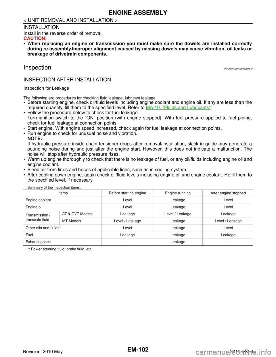
Summary of the inspection items:
*: Power steering fluid, brake fluid, etc. Items Before starting engine Engine running After engine stopped
Engine coolant Level Leakage Level
Engine oil Level Leakage Level
Transmission /
transaxle fluid AT & CVT Models Leakage Level / Leakage Leakage
MT Models Level / Leakage Leakage Level / Leakage
Other oils and fluids* Level Leakage Level
Fuel Leakage Leakage Leakage
Exhaust gases — Leakage —
Revision: 2010 May2011 QX56
Page 2719 of 5598
![INFINITI QX56 2011 Factory Service Manual
COMPONENT PARTSEXL-9
< SYSTEM DESCRIPTION > [XENON TYPE]
C
D
E
F
G H
I
J
K
M A
B
EXL
N
O P
FRONT COMBINATION LAMP : HID control unitINFOID:0000000006213890
Headlamp (LO) circuit is connected to HID c INFINITI QX56 2011 Factory Service Manual
COMPONENT PARTSEXL-9
< SYSTEM DESCRIPTION > [XENON TYPE]
C
D
E
F
G H
I
J
K
M A
B
EXL
N
O P
FRONT COMBINATION LAMP : HID control unitINFOID:0000000006213890
Headlamp (LO) circuit is connected to HID c](/manual-img/42/57033/w960_57033-2718.png)
COMPONENT PARTSEXL-9
< SYSTEM DESCRIPTION > [XENON TYPE]
C
D
E
F
G H
I
J
K
M A
B
EXL
N
O P
FRONT COMBINATION LAMP : HID control unitINFOID:0000000006213890
Headlamp (LO) circuit is connected to HID control unit integrated in the headlamp. Headlamp (LO) circuit turns
xenon headlamp ON.
For the details of HID control unit and the xenon headlamp, refer to EXL-8, "
FRONT COMBINATION LAMP :
Xenon Headlamp".
FRONT COMBINATION LAMP : High Beam SolenoidINFOID:0000000006213891
The high beam solenoid drives the mobile valve shade. And the mobile valve shade switches the high beam
and low beam of headlamp.
When the headlamp high relay is turned ON, magnetic force is applied to the high beam solenoid (1) by a current. The mobile
valve shade (2) is switched to the high beam position.
When the headlamp high relay is turned OFF, the current stops.
The mobile valve shade returns to the low beam position automati-
cally.
FRONT COMBINATION LAMP : Aiming MotorINFOID:0000000006213892
The headlamp levelizer adjusts the headlamp light axis upward and downward with the aiming motor inte-
grated in the front combination lamp.
FRONT COMBINATION LAMP : Swivel ActuatorINFOID:0000000006213893
SWIVEL ACTUATOR
The swivel actuator is installed in the headlamp unit. T he swivel actuator consists of the swivel motor and the
swivel position sensor.
SWIVEL MOTOR
The swivel motor is the two-phase step motor.
The swivel motor drives headlamp by exciting the two dr ive coils according to the drive signal from AFS con-
trol unit.
The rotation direction of the swivel motor is changeable by changing the exciting pattern.
SWIVEL POSITION SENSOR
The swivel position sensor detects the headlamp swivel angle to transmit t he swivel position sensor signal to
AFS control unit.
JSLIA0129ZZ
Revision: 2010 May2011 QX56
Page 2948 of 5598
FSU-6
< PERIODIC MAINTENANCE >
FRONT SUSPENSION ASSEMBLY
PERIODIC MAINTENANCE
FRONT SUSPENSION ASSEMBLY
InspectionINFOID:0000000006225639
MOUNTING INSPECTION
Check the mounting conditions (looseness, backlash) of each component and component conditions (wear,
damage) are normal.
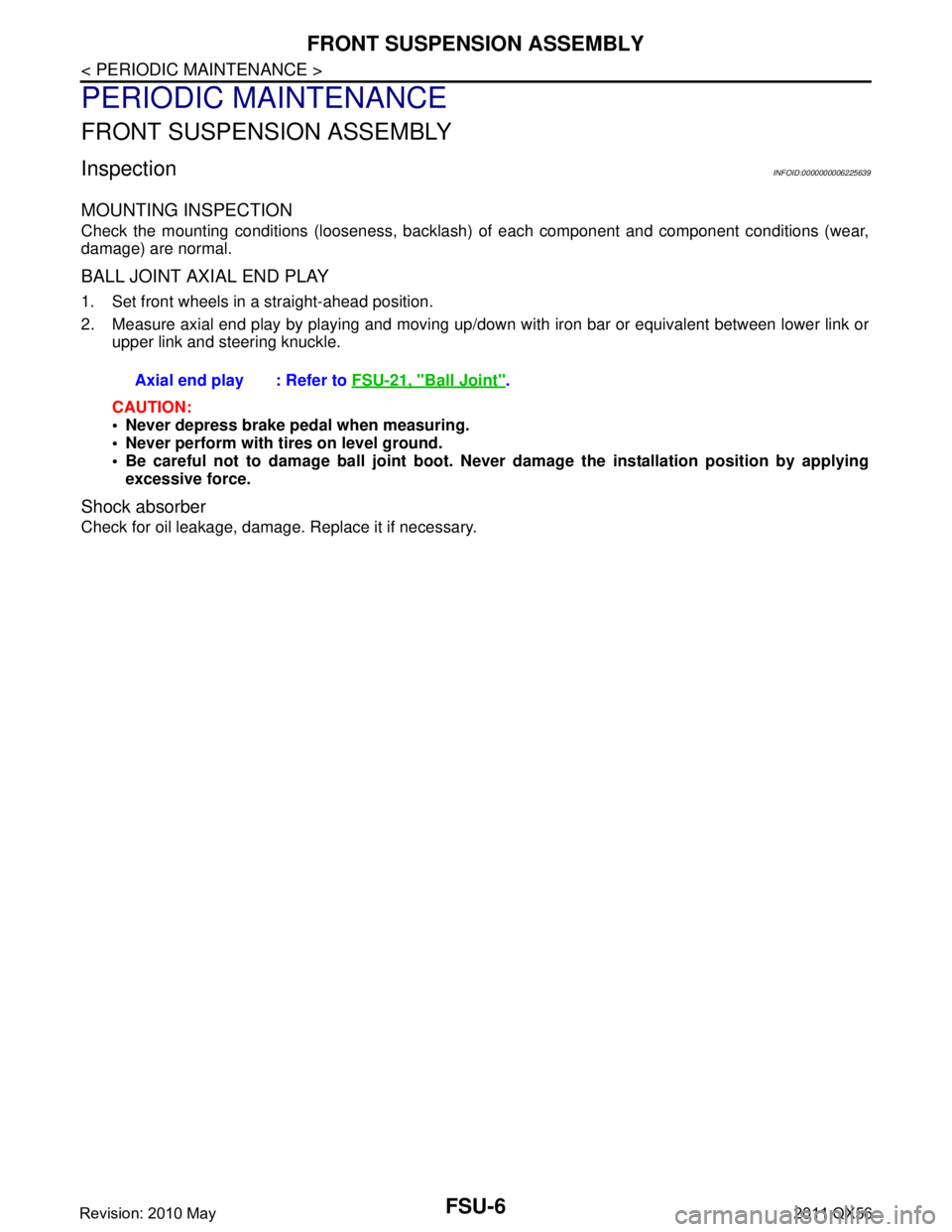
BALL JOINT AXIAL END PLAY
1. Set front wheels in a straight-ahead position.
2. Measure axial end play by playing and moving up/dow n with iron bar or equivalent between lower link or
upper link and steering knuckle.
CAUTION:
Never depress brake pedal when measuring.
Never perform with tires on level ground.
Be careful not to damage ball joint boot. Never damage the installation position by applying
excessive force.
Shock absorber
Check for oil leakage, damage. Replace it if necessary. Axial end play : Refer to
FSU-21, "
Ball Joint".
Revision: 2010 May2011 QX56
Page 2953 of 5598
FRONT COIL SPRING AND SHOCK ABSORBERFSU-11
< REMOVAL AND INSTALLATION >
C
DF
G H
I
J
K L
M A
B
FSU
N
O P
12. Separate drive shaft from steering knuckle. (4WD) Refer to FAX-22, "Removal and Installation".
13. Remove front tube assembly A and front tube asse mbly B from shock absorber. (With HBMC) Refer to
SCS-32, "
FRONT TUBE ASSEMBLY : Removal and Installation".
14. Remove shock absorber.
15. Perform inspection after removal. (With HBMC) Refer to FSU-12, "
Inspection and Adjustment".
INSTALLATION
Note the following, and install in the reverse order of removal.
Never tap on the ball joint cap of the stabilizer connecting rod with a hammer or a similar item when inserting
the stabilizer connecting rod into the lower link. (Without HBMC)
Perform final tightening of bolts and nuts at the shock absorber lower side (rubber bushing), under unladen
conditions with tires on level ground.
Perform inspection after installation. Refer to FSU-12, "
Inspection and Adjustment".
Perform adjustment after installation. (With HBMC) Refer to FSU-12, "
Inspection and Adjustment".
After replacing the shock absorber, always follow the disposal procedure to discard the shock absorber.
Refer to FSU-13, "
Disposal".
Disassembly and AssemblyINFOID:0000000006273960
CAUTION:
The shock absorber assembly can not be disassembled. (With HBMC)
DISASSEMBLY (WITHOUT HBMC)
CAUTION:
Never damage shock absorber piston rod wh en removing components from shock absorber.
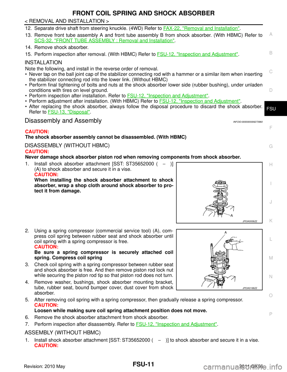
1. Install shock absorber attachment [SST: ST35652000 ( −)]
(A) to shock absorber and secure it in a vise.
CAUTION:
When installing the shock ab sorber attachment to shock
absorber, wrap a shop cloth around shock absorber to pro-
tect it from damage.
2. Using a spring compressor (commercial service tool) (A), com- press coil spring between rubber seat and shock absorber until
coil spring with a spring compressor is free.
CAUTION:
Be sure a spring compresso r is securely attached coil
spring. Compress coil spring
3. Check coil spring with a spring compressor between rubber seat and shock absorber is free. And then remove piston rod lock nut
while securing the piston rod tip so that piston rod does not turn.
4. Remove washer, bushings, shock absorber mounting bracket, tube, rubber seat, bound bumper cover, dust cover from shock
absorber.
5. After removing coil spring with a spring compressor, then gradually release a spring compressor. CAUTION:
Loosen while making sure coil spri ng attachment position does not move.
6. Remove the shock absorber at tachment from shock absorber.
7. Perform inspection after disassembly. Refer to FSU-12, "
Inspection and Adjustment".
ASSEMBLY (WITHOUT HBMC)
1. Install shock absorber attachment [SST: ST35652000 ( −)] to shock absorber and secure it in a vise.
CAUTION:
JPEIA0006ZZ
JPEIA0168ZZ
Revision: 2010 May2011 QX56
Page 2955 of 5598
FRONT COIL SPRING AND SHOCK ABSORBERFSU-13
< REMOVAL AND INSTALLATION >
C
DF
G H
I
J
K L
M A
B
FSU
N
O P
3. Adjust neutral position of steering angle sensor. Refer to BRC-64, "Work Procedure".
4. Adjust levelizer adjustment of height sensor. Refer to EXL-61, "
LEVELIZER ADJUSTMENT : Special
Repair Requirement".
ADJUSTMENT AFTER INSTALLATION (WITH HBMC)
Bleed air from the HBMC. Refer to SCS-18, "Work Procedure".
DisposalINFOID:0000000006225645
WITHOUT HBMC
1. Set shock absorber horizontally with the piston rod fully extended.
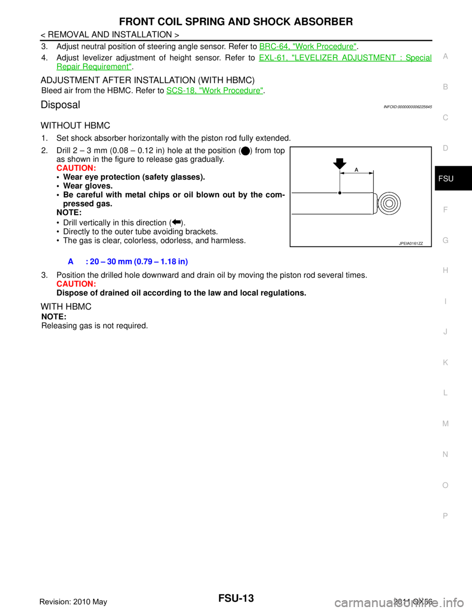
2. Drill 2 – 3 mm (0.08 – 0.12 in) hole at the position ( ) from top
as shown in the figure to release gas gradually.
CAUTION:
Wear eye protection (safety glasses).
Wear gloves.
Be careful with metal chips or oil blown out by the com-
pressed gas.
NOTE:
Drill vertically in this direction ( ).
Directly to the outer tube avoiding brackets.
The gas is clear, colorless, odorless, and harmless.
3. Position the drilled hole downward and drain oil by moving the piston rod several times. CAUTION:
Dispose of drained oil according to the law and local regulations.
WITH HBMC
NOTE:
Releasing gas is not required.A : 20 – 30 mm (0.79 – 1.18 in)
JPEIA0161ZZ
Revision: 2010 May2011 QX56
Page 2979 of 5598

ABBREVIATIONSGI-15
< HOW TO USE THIS MANUAL >
C
DE
F
G H
I
J
K L
M B
GI
N
O P
E
F
G
H
ABBREVIATION DESCRIPTION E/T Exhaust temperature
EBD Electric brake force distribution EC Engine control
ECL Engine coolant level
ECM Engine control module ECT Engine coolant temperature
ECV Electrical control valve
EEPROM Electrically erasable programmable read only memory EFT Engine fuel temperature
EGR Exhaust gas recirculation
EGRT Exhaust gas recirculation temperature EGT Exhaust gas temperature
EOP Engine oil pressure EP Exhaust pressure
EPR Exhaust pressure regulator EPS Electronically controlled power steering
ESP Electronic stability program system
EVAP canister Evaporative emission canister EXC Exhaust control
ABBREVIATION DESCRIPTION FC Fan control
FCW Forward collision warning FIC Fuel injector controlFP Fuel pump
FR Front
FRP Fuel rail pressure FRT Fuel rail temperature
FTP Fuel tank pressure FTT Fuel tank temperature
ABBREVIATION DESCRIPTION GND GroundGPS Global positioning systemGST Generic scan tool
ABBREVIATION DESCRIPTION HBMC Hydraulic body-motion control systemHDD Hard disk drive
HO2S Heated oxygen sensor HOC Heated oxidation catalyst
Revision: 2010 May2011 QX56