2011 INFINITI QX56 oil level
[x] Cancel search: oil levelPage 2388 of 5598
![INFINITI QX56 2011 Factory Service Manual
EC-364
< DTC/CIRCUIT DIAGNOSIS >[VK56VD]
P0524 ENGINE OIL PRESSURE
P0524 ENGINE OIL PRESSURE
DTC LogicINFOID:0000000006288342
DTC DETECTION LOGIC
NOTE:
If DTC P0524 is displayed with DTC P0075 or P00 INFINITI QX56 2011 Factory Service Manual
EC-364
< DTC/CIRCUIT DIAGNOSIS >[VK56VD]
P0524 ENGINE OIL PRESSURE
P0524 ENGINE OIL PRESSURE
DTC LogicINFOID:0000000006288342
DTC DETECTION LOGIC
NOTE:
If DTC P0524 is displayed with DTC P0075 or P00](/manual-img/42/57033/w960_57033-2387.png)
EC-364
< DTC/CIRCUIT DIAGNOSIS >[VK56VD]
P0524 ENGINE OIL PRESSURE
P0524 ENGINE OIL PRESSURE
DTC LogicINFOID:0000000006288342
DTC DETECTION LOGIC
NOTE:
If DTC P0524 is displayed with DTC P0075 or P0081,
perform trouble diagnosis for DTC P0075 or P0081
first. Refer to EC-193, "
DTC Logic".
DTC CONFIRMATION PROCEDURE
1.PRECONDITIONING-I
1. Turn ignition switch OFF and wait at least 10 seconds.
2. Turn ignition switch ON.
3. Turn ignition switch OFF and wait at least 10 seconds.
TESTING CONDITION:
Before performing the following procedure, confi rm that battery voltage is between 10 V and 16 V at
idle.
>> GO TO 2.
2.PRECONDITIONING-II
Check oil level and oil pressure. Refer to LU-7, "
Inspection".
Is the inspection result normal?
YES >> GO TO 3.
NO >> Proceed to LU-7, "
Inspection".
3.PERFORM DTC CONFIRMATION PROCEDURE
WITH CONSULT-III
1. Select “DATA MONITOR” mode with CONSULT-III.
2. Maintain the following conditions for at least 20 consecutive seconds.
CAUTION:
Always drive at a safe speed.
3. Check 1st trip DTC.
WITH GST
Follow the procedure “With CONSULT-III” above.
Is 1st trip DTC detected?
YES >> Proceed to EC-365, "Diagnosis Procedure"
DTC No.Trouble diagnosis name
(Trouble diagnosis content) Detecting condition Possible cause
P0524 ENGINE OIL PRESSURE
(Engine oil pressure too low) Engine oil pressure is low because
there is a gap between angle of target
and phase-control angle. Engine oil pressure or level too low
Crankshaft position sensor
Camshaft position sensor
Intake valve timing control solenoid valve
Accumulation of debris to the signal pick-up por-
tion of the camshaft
Timing chain installation
Foreign matter caught in the oil groove for intake valve timing control
ENG SPEED More than 1,700 rpm
COOLAN TEMP/S More than 70 °C (158 °F)
Selector lever 1st or 2nd position
Driving location uphill Driving vehicle uphill
(Increased engine load will help maintain the driving
conditions required for this test.)
Revision: 2010 May2011 QX56
Page 2424 of 5598
![INFINITI QX56 2011 Factory Service Manual
EC-400
< DTC/CIRCUIT DIAGNOSIS >[VK56VD]
P1217 ENGINE OVER TEMPERATURE
P1217 ENGINE OVER TEMPERATURE
DTC LogicINFOID:0000000006217909
DTC DETECTION LOGIC
NOTE:
If DTC P1217 is displayed with DTC UX INFINITI QX56 2011 Factory Service Manual
EC-400
< DTC/CIRCUIT DIAGNOSIS >[VK56VD]
P1217 ENGINE OVER TEMPERATURE
P1217 ENGINE OVER TEMPERATURE
DTC LogicINFOID:0000000006217909
DTC DETECTION LOGIC
NOTE:
If DTC P1217 is displayed with DTC UX](/manual-img/42/57033/w960_57033-2423.png)
EC-400
< DTC/CIRCUIT DIAGNOSIS >[VK56VD]
P1217 ENGINE OVER TEMPERATURE
P1217 ENGINE OVER TEMPERATURE
DTC LogicINFOID:0000000006217909
DTC DETECTION LOGIC
NOTE:
If DTC P1217 is displayed with DTC UXXXX, perform the trouble diagnosis for DTC UXXXX.
If DTC P1217 is displayed with DTC P0607, perfo rm the trouble diagnosis for DTC P0607. Refer to
EC-378, "
DTC Logic".
If DTC P1217 is displayed with DTC P0527, perfo rm the trouble diagnosis for DTC P0527. Refer to
EC-367, "
DTC Logic".
If the cooling fan or any of other components in the cooling system has a malfunction, engine coolant temper-
ature increases.
When the engine coolant temperature reaches an abnorma lly high temperature condition, a malfunction is
indicated.
CAUTION:
When a malfunction is indicated, al ways replace the coolant. Refer to CO-8, "
Draining" and CO-9,
"Refilling". Also, replace the engine oil. Refer to LU-8, "Draining" and LU-8, "Refilling".
1. Fill radiator with coolant up to specified level with a filling speed of 2 liters per minute. Always use
coolant with the proper mixture ratio. Refer to MA-11, "
Anti-Freeze Coolant Mixture Ratio".
2. After refilling coolant, run engine to en sure that no water-flow noise is emitted.
DTC CONFIRMATION PROCEDURE
1.PERFORM COMPONENT FUNCTION CHECK
Perform component function check. Refer to EC-400, "
Component Function Check".
NOTE:
Use component function check to check the overall functi on of the cooling fan. During this check, a DTC might
not be confirmed.
Is the inspection result normal?
YES >> INSPECTION END
NO >> Go to EC-401, "
Diagnosis Procedure".
Component Function CheckINFOID:0000000006217910
1.PERFORM COMPONENT FUNCTION CHECK-I
WARNING:
Never remove the reservoir tank cap when the engi ne is hot. Serious burns could be caused by high
pressure fluid escaping from the radiator.
Wrap a thick cloth around cap. Carefully remove the cap by turning it a quarter turn to allow built-up
pressure to escape. Then turn the cap all the way off.
DTC No. Trouble diagnosis name DTC detecting condition Possible cause
P1217 Engine over temperature
(Overheat) Cooling fan does not operate properly
(Overheat).
Cooling fan system does not operate properly (Overheat).
Engine coolant is not within the specified quantity. Harness or connectors
(The cooling fan circuit is open or shorted.)
IPDM E/R
Electrically-controlled cooling fan coupling
Cooling fan speed sensor
Radiator hose
Radiator
Reservoir tank cap
Water pump
Thermostat
Revision: 2010 May2011 QX56
Page 2552 of 5598
![INFINITI QX56 2011 Factory Service Manual
E C -528
< SYMPTOM DIAGNOSIS >[VK56VD]
ENGINE CONTROL SYSTEM SYMPTOMS
1 - 6: The numbers refer to the order of inspection.Lubrica-
tion
Oil pan/Oil strainer/Oil pump/Oil
filter/Oil gallery/Oil coole INFINITI QX56 2011 Factory Service Manual
E C -528
< SYMPTOM DIAGNOSIS >[VK56VD]
ENGINE CONTROL SYSTEM SYMPTOMS
1 - 6: The numbers refer to the order of inspection.Lubrica-
tion
Oil pan/Oil strainer/Oil pump/Oil
filter/Oil gallery/Oil coole](/manual-img/42/57033/w960_57033-2551.png)
E C -528
< SYMPTOM DIAGNOSIS >[VK56VD]
ENGINE CONTROL SYSTEM SYMPTOMS
1 - 6: The numbers refer to the order of inspection.Lubrica-
tion
Oil pan/Oil strainer/Oil pump/Oil
filter/Oil gallery/Oil cooler 55555 55 5 EM-56
EM-60
LU-9
LU-12
LU-14
Oil level (Low)/Filthy oil
LU-7
Cooling
Radiator/Hose/Radiator filler cap
55555 55 45 CO-11
CO-11
Thermostat 5
CO-21
Water pumpCO-19
Water galleryEM-115
Cooling fan
5CO-17
Coolant level (Low)/Contaminat-
ed coolant
CO-8
IVIS (INFINITI Vehicle Immobilizer System —
NATS)11
SEC-48
SYMPTOM
Reference
page
HARD/NO START/RESTART (EXCP. HA)
ENGINE STALL
HESITATION/SURGING/FLAT SPOT
SPARK KNOCK/DETONATION
LACK OF POWER/POOR ACCELERATION
HIGH IDLE/LOW IDLE
ROUGH IDLE/HUNTING
IDLING VIBRATION
SLOW/NO RETURN TO IDLE
OVERHEATS/WATER TEMPERATURE HIGH
EXCESSIVE FUEL CONSUMPTION
EXCESSIVE OIL CONSUMPTION
BATTERY DEAD (UNDER CHARGE)
Warranty symptom code AA AB AC AD AE AF AG AH AJ AK AL AM HA
Revision: 2010 May2011 QX56
Page 2578 of 5598
EM-16
< BASIC INSPECTION >
COMPRESSION PRESSURE
COMPRESSION PRESSURE
InspectionINFOID:0000000006289521
1. Warm up engine thoroughly. Then, stop it.
2. Release fuel pressure. Refer to EC-153, "
Work Procedure".
CAUTION:
If CONSULT-III is not used to release fuel pr essure leave the fuel pump fuse disconnected until
step 7.
3. Remove fuel pump fuse in IPDM E/R. NOTE:
For the fuse number, refer to EC-114, "
Wiring Diagram".
For the fuse arrangement, refer to PG-143, "
Fuse, Connector and Terminal Arrangement".
4. Remove engine cover. Refer to EM-25, "
Exploded View".
5. Remove ignition coil and spark plug from each cylinder. Refer to EM-29, "
Exploded View".
6. Connect engine tachometer (not required in use of CONSULT-III).
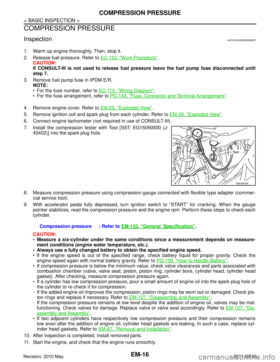
7. Install the compression tester with Tool [SST: EG15050500 (J- 45402)] into the spark plug hole.
8. Measure compression pressure using compressi on gauge connected with flexible type adapter (commer-
cial service tool).
9. With accelerator pedal fully depressed, turn ignition switch to “START” for cranking. When the gauge pointer stabilizes, read the compression pressure and the engine rpm. Perform these steps to check each
cylinder.
CAUTION:
Measure a six-cylinder under the same conditio ns since a measurement depends on measure-
ment conditions (engine water temperature, etc.).
Always use a fully changed battery to obtain the specified engine speed.
If the engine speed is out of the specified range, c heck battery liquid for proper gravity. Check the
engine speed again with normal battery gravity. Refer to PG-159, "
How to Handle Battery".
If compression pressure is below the minimum value, check valve clearances and parts associated with combustion chamber (valve, valve seat, piston, pi ston ring, cylinder bore, cylinder head, cylinder head
gasket). After checking, measure compression pressure again.
If a cylinder has low compression pressure, pour a small amount of engine oil into the spark plug hole of the cylinder to re-check it for compression.
- If the added engine oil improves the compression, pi ston rings may be worn out or damaged. Check pis-
ton rings and replace if necessary. Refer to EM-107, "
Disassembly and Assembly".
- If the compression pressure remains at low level despite the addition of engine oil, valves may be mal- functioning. Check valves for damage. Replace valve or valve seat accordingly. Refer to EM-107, "
Dis-
assembly and Assembly".
If two adjacent cylinders have respectively low co mpression pressure and their compression remains
low even after the addition of engine oil, cylinder head gaskets are leaking. In such a case, replace cyl-
inder head gaskets. Refer to EM-87, "
Removal and Installation".
10. After inspection is completed, install removed parts.
11. Start the engine, and check that the engine runs smoothly.
WBIA0605E
Compression pressure : Refer to EM-132, "GeneralSpecification".
Revision: 2010 May2011 QX56
Page 2595 of 5598
ROCKER COVEREM-33
< REMOVAL AND INSTALLATION >
C
DE
F
G H
I
J
K L
M A
EM
NP
O
ROCKER COVER
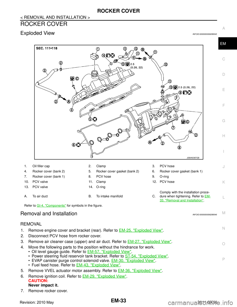
Exploded ViewINFOID:0000000006289545
Removal and InstallationINFOID:0000000006289546
REMOVAL
1. Remove engine cover and bracket (rear). Refer to
EM-25, "Exploded View".
2. Disconnect PCV hose from rocker cover.
3. Remove air cleaner case (upper) and air duct. Refer to EM-27, "
Exploded View".
4. Move the following parts to the position without the hindrance for work. Oil level gauge guide. Refer to EM-57, "
Exploded View".
Power steering fluid reservoir tank bracket. Refer to ST-54, "
Exploded View".
EVAP canister purge control solenoid valve. EM-30, "
Exploded View".
Fuel feed hose. Refer to EM-43, "
Exploded View".
5. Remove VVEL actuator motor assembly. Refer to EM-36, "
Exploded View".
6. Remove ignition coil. Refer to EM-29, "
Exploded View".
CAUTION:
Never impact it.
7. Remove rocker cover.
1. Oil filler cap 2. Clamp 3. PCV hose
4. Rocker cover (bank 2) 5. Rocker cover gasket (bank 2) 6. Rocker cover gasket (bank 1)
7. Rocker cover (bank 1) 8. PCV hose 9. O-ring
10. PCV valve 11. Clamp 12. PCV hose
13. PCV valve 14. O-ring
A. To air duct B. To intake manifold C. Comply with the installation proce-
dure when tightening. Refer to
EM-
33, "Removal and Installation".
Refer to GI-4, "
Components" for symbols in the figure.
JSBIA0387GB
Revision: 2010 May2011 QX56
Page 2603 of 5598
EXHAUST MANIFOLD AND THREE WAY CATALYST
EM-41
< REMOVAL AND INSTALLATION >
C
D E
F
G H
I
J
K L
M A
EM
NP
O
11. Remove front propeller shaft. Refer to
DLN-128, "Exploded View".
12. Disconnect steering lower joint. Refer to ST-37, "
Exploded View".
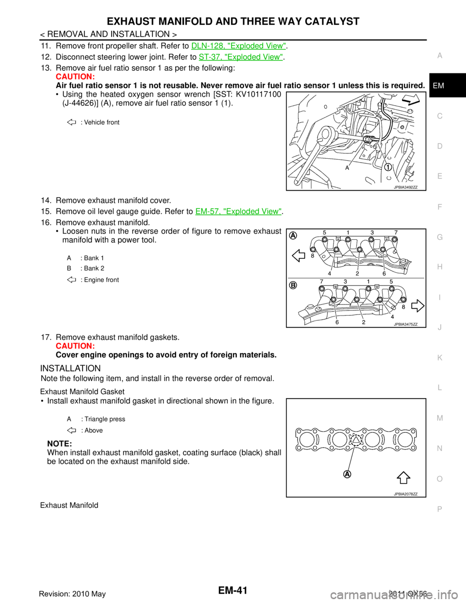
13. Remove air fuel ratio sensor 1 as per the following: CAUTION:
Air fuel ratio sensor 1 is not reusable. Never remo ve air fuel ratio sensor 1 unless this is required.
Using the heated oxygen sensor wrench [SST: KV10117100
(J-44626)] (A), remove air fuel ratio sensor 1 (1).
14. Remove exhaust manifold cover.
15. Remove oil level gauge guide. Refer to EM-57, "
Exploded View".
16. Remove exhaust manifold. Loosen nuts in the reverse order of figure to remove exhaustmanifold with a power tool.
17. Remove exhaust manifold gaskets. CAUTION:
Cover engine openings to avoid entry of foreign materials.
INSTALLATION
Note the following item, and install in the reverse order of removal.
Exhaust Manifold Gasket
Install exhaust manifold gasket in directional shown in the figure.
NOTE:
When install exhaust manifold gasket, coating surface (black) shall
be located on the exhaust manifold side.
Exhaust Manifold
: Vehicle front
JPBIA3492ZZ
A : Bank 1
B : Bank 2 : Engine front
JPBIA3475ZZ
A : Triangle press : Above
JPBIA2078ZZ
Revision: 2010 May2011 QX56
Page 2616 of 5598
EM-54
< REMOVAL AND INSTALLATION >
OIL PAN (LOWER) AND OIL STRAINER
OIL PAN (LOWER) AND OIL STRAINER
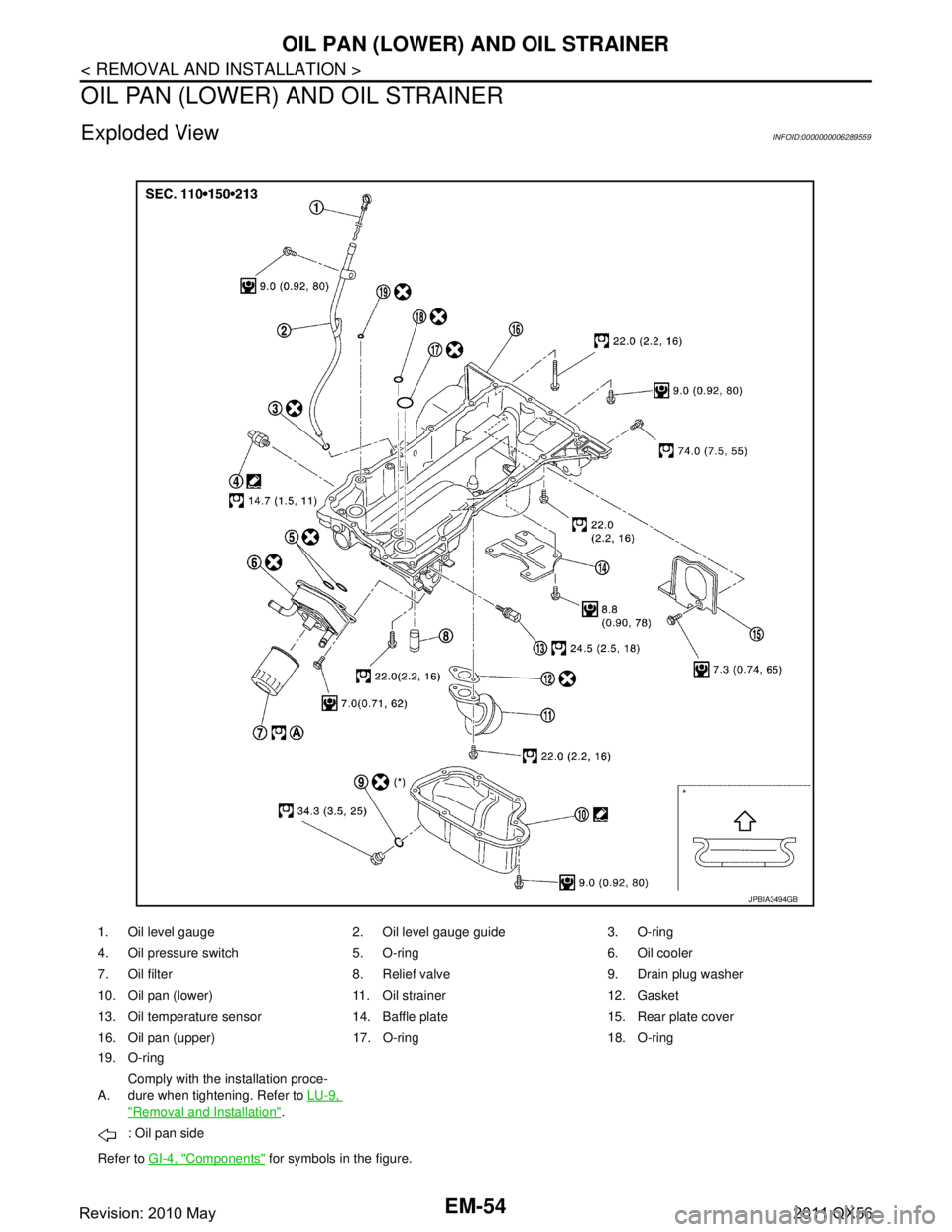
Exploded ViewINFOID:0000000006289559
1. Oil level gauge 2. Oil level gauge guide 3. O-ring
4. Oil pressure switch 5. O-ring 6. Oil cooler
7. Oil filter 8. Relief valve 9. Drain plug washer
10. Oil pan (lower) 11. Oil strainer 12. Gasket
13. Oil temperature sensor 14. Baffle plate 15. Rear plate cover
16. Oil pan (upper) 17. O-ring 18. O-ring
19. O-ring
A.Comply with the installation proce-
dure when tightening. Refer to
LU-9,
"Removal and Installation".
: Oil pan side
Refer to GI-4, "
Components" for symbols in the figure.
JPBIA3494GB
Revision: 2010 May2011 QX56
Page 2618 of 5598
EM-56
< REMOVAL AND INSTALLATION >
OIL PAN (LOWER) AND OIL STRAINER
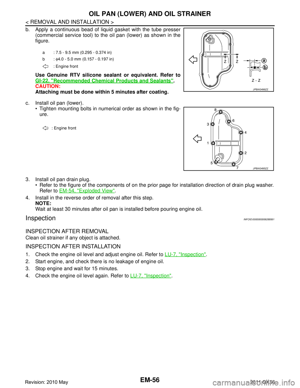
b. Apply a continuous bead of liquid gasket with the tube presser(commercial service tool) to the oil pan (lower) as shown in the
figure.
Use Genuine RTV silicone seal ant or equivalent. Refer to
GI-22, "
Recommended Chemical Products and Sealants".
CAUTION:
Attaching must be done with in 5 minutes after coating.
c. Install oil pan (lower). Tighten mounting bolts in numerical order as shown in the fig-ure.
3. Install oil pan drain plug. Refer to the figure of the components of on the prior page for installation direction of drain plug washer.Refer to EM-54, "
Exploded View".
4. Install in the reverse order of removal after this step. NOTE:
Wait at least 30 minutes after oil pan is installed before pouring engine oil.
InspectionINFOID:0000000006289561
INSPECTION AFTER REMOVAL
Clean oil strainer if any object is attached.
INSPECTION AFTER INSTALLATION
1. Check the engine oil level and adjust engine oil. Refer to LU-7, "Inspection".
2. Start engine, and check there is no leakage of engine oil.
3. Stop engine and wait for 15 minutes.
4. Check the engine oil level again. Refer to LU-7, "
Inspection".
a : 7.5 - 9.5 mm (0.295 - 0.374 in)
b: φ4.0 - 5.0 mm (0.157 - 0.197 in)
: Engine front
JPBIA3496ZZ
: Engine front
JPBIA3495ZZ
Revision: 2010 May2011 QX56