2011 FORD KUGA oil
[x] Cancel search: oilPage 1763 of 2057
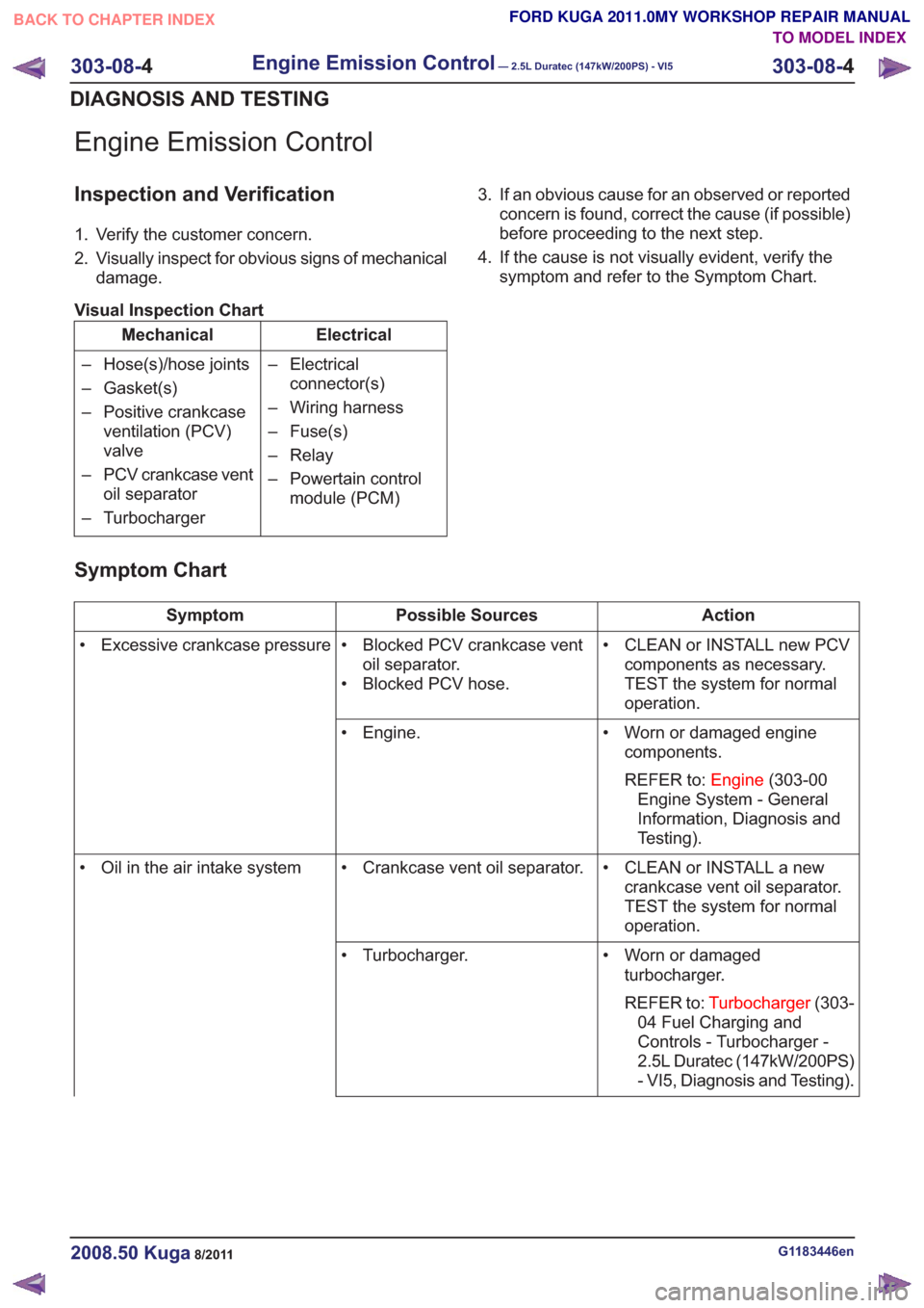
Engine Emission Control
Inspection and Verification
1. Verify the customer concern.
2. Visually inspect for obvious signs of mechanicaldamage.
Visual Inspection Chart
Electrical
Mechanical
– Electricalconnector(s)
– Wiring harness
– Fuse(s)
– Relay
– Powertain control module (PCM)
– Hose(s)/hose joints
– Gasket(s)
– Positive crankcase
ventilation (PCV)
valve
– PCV crankcase vent oil separator
– Turbocharger 3. If an obvious cause for an observed or reported
concern is found, correct the cause (if possible)
before proceeding to the next step.
4. If the cause is not visually evident, verify the symptom and refer to the Symptom Chart.
Symptom Chart
Action
Possible Sources
Symptom
• CLEAN or INSTALL new PCVcomponents as necessary.
TEST the system for normal
operation.
• Blocked PCV crankcase vent
oil separator.
• Blocked PCV hose.
• Excessive crankcase pressure
• Worn or damaged enginecomponents.
REFER to: Engine(303-00
Engine System - General
Information, Diagnosis and
Testing).
• Engine.
• CLEAN or INSTALL a newcrankcase vent oil separator.
TEST the system for normal
operation.
• Crankcase vent oil separator.
• Oil in the air intake system
• Worn or damagedturbocharger.
REFER to: Turbocharger (303-
04 Fuel Charging and
Controls - Turbocharger -
2.5L Duratec (147kW/200PS)
- VI5, Diagnosis and Testing).
• Turbocharger.
G1183446en2008.50 Kuga8/2011
303-08-
4
Engine Emission Control— 2.5L Duratec (147kW/200PS) - VI5303-08-
4
DIAGNOSIS AND TESTING
TO MODEL INDEX
BACK TO CHAPTER INDEX
FORD KUGA 2011.0MY WORKSHOP REPAIR MANUAL
Page 1768 of 2057
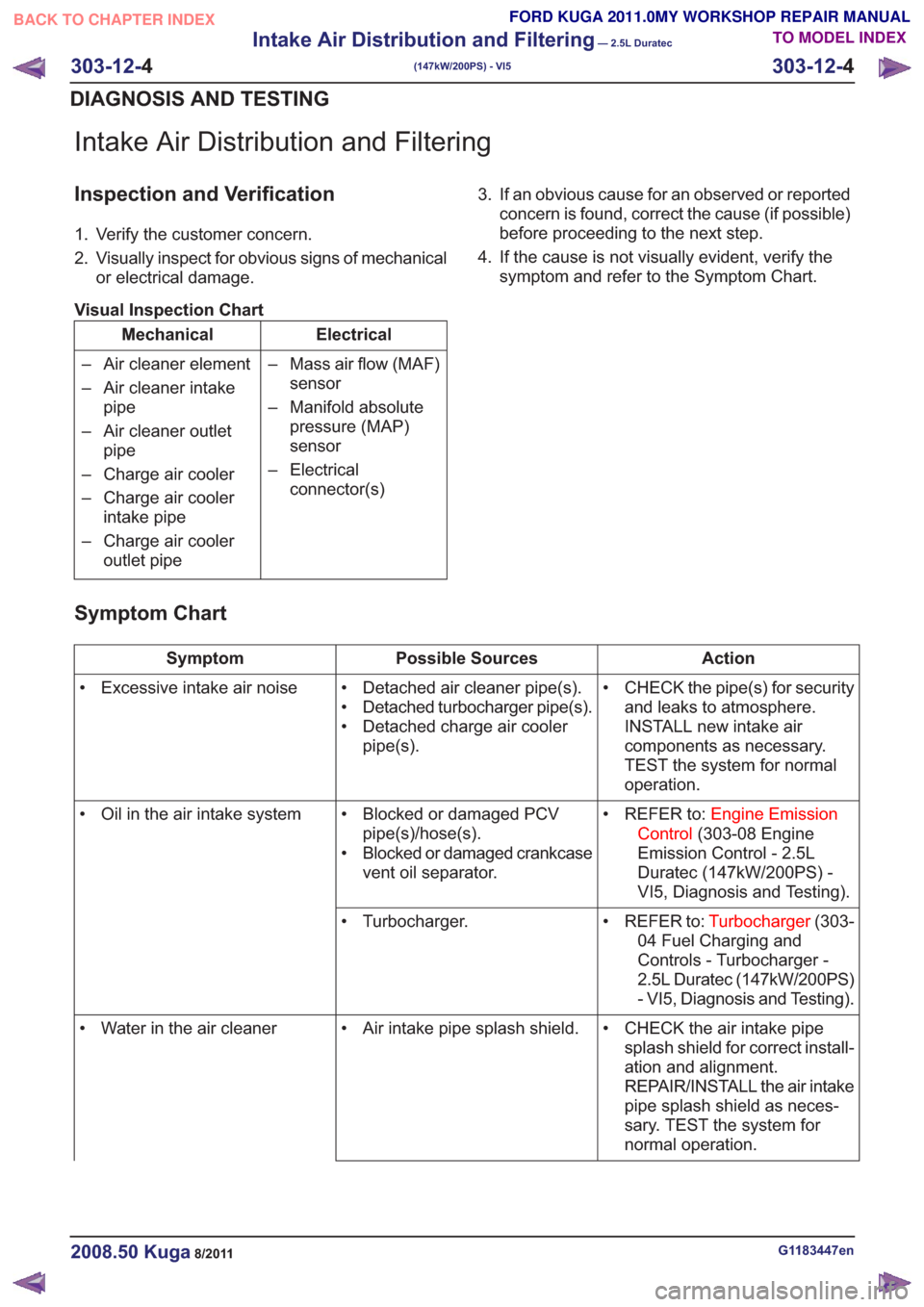
Intake Air Distribution and Filtering
Inspection and Verification
1. Verify the customer concern.
2. Visually inspect for obvious signs of mechanicalor electrical damage.
Visual Inspection Chart
Electrical
Mechanical
– Mass air flow (MAF)sensor
– Manifold absolute pressure (MAP)
sensor
– Electrical connector(s)
– Air cleaner element
– Air cleaner intake
pipe
– Air cleaner outlet pipe
– Charge air cooler
– Charge air cooler intake pipe
– Charge air cooler outlet pipe 3. If an obvious cause for an observed or reported
concern is found, correct the cause (if possible)
before proceeding to the next step.
4. If the cause is not visually evident, verify the symptom and refer to the Symptom Chart.
Symptom Chart
Action
Possible Sources
Symptom
• CHECK the pipe(s) for securityand leaks to atmosphere.
INSTALL new intake air
components as necessary.
TEST the system for normal
operation.
• Detached air cleaner pipe(s).
• Detached turbocharger pipe(s).
• Detached charge air cooler
pipe(s).
• Excessive intake air noise
• REFER to:Engine Emission
Control (303-08 Engine
Emission Control - 2.5L
Duratec (147kW/200PS) -
VI5, Diagnosis and Testing).
• Blocked or damaged PCV
pipe(s)/hose(s).
• Blocked or damaged crankcase vent oil separator.
• Oil in the air intake system
• REFER to:Turbocharger(303-
04 Fuel Charging and
Controls - Turbocharger -
2.5L Duratec (147kW/200PS)
- VI5, Diagnosis and Testing).
• Turbocharger.
• CHECK the air intake pipesplash shield for correct install-
ation and alignment.
REPAIR/INSTALL the air intake
pipe splash shield as neces-
sary. TEST the system for
normal operation.
• Air intake pipe splash shield.
• Water in the air cleaner
G1183447en2008.50 Kuga8/2011
303-12- 4
Intake Air Distribution and Filtering
— 2.5L Duratec
(147kW/200PS) - VI5
303-12- 4
DIAGNOSIS AND TESTING
TO MODEL INDEX
BACK TO CHAPTER INDEX
FORD KUGA 2011.0MY WORKSHOP REPAIR MANUAL
Page 1775 of 2057
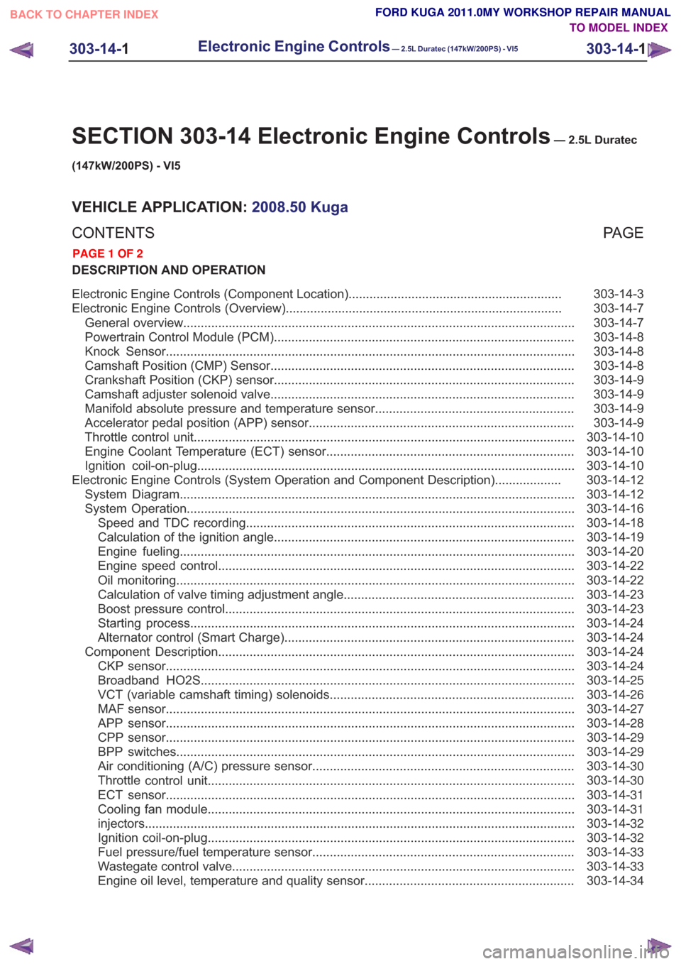
SECTION 303-14 Electronic Engine Controls— 2.5L Duratec
(147kW/200PS) - VI5
VEHICLE APPLICATION: 2008.50 Kuga
PA G E
CONTENTS
DESCRIPTION AND OPERATION
303-14-3
Electronic Engine Controls (Component Location) .............................................................
303-14-7
Electronic Engine Controls (Overview) ........................................................................\
.......
303-14-7
General overview ........................................................................\
........................................
303-14-8
Powertrain Control Module (PCM) ........................................................................\
..............
303-14-8
Knock Sensor ........................................................................\
.............................................
303-14-8
Camshaft Position (CMP) Sensor ........................................................................\
...............
303-14-9
Crankshaft Position (CKP) sensor ........................................................................\
..............
303-14-9
Camshaft adjuster solenoid valve........................................................................\
...............
303-14-9
Manifold absolute pressure and temperature sensor .........................................................
303-14-9
Accelerator pedal position (APP) sensor ........................................................................\
....
303-14-10
Throttle control unit ........................................................................\
.....................................
303-14-10
Engine Coolant Temperature (ECT) sensor.......................................................................
303-14-10
Ignition coil-on-plug ........................................................................\
....................................
303-14-12
Electronic Engine Controls (System Operation and Component Description) ...................
303-14-12
System Diagram ........................................................................\
.........................................
303-14-16
System Operation ........................................................................\
.......................................
303-14-18
Speed and TDC recording ........................................................................\
......................
303-14-19
Calculation of the ignition angle ........................................................................\
..............
303-14-20
Engine fueling ........................................................................\
.........................................
303-14-22
Engine speed control ........................................................................\
..............................
303-14-22
Oil monitoring ........................................................................\
..........................................
303-14-23
Calculation of valve timing adjustment angle..................................................................
303-14-23
Boost pressure control ........................................................................\
............................
303-14-24
Starting process ........................................................................\
......................................
303-14-24
Alternator control (Smart Charge) ........................................................................\
...........
303-14-24
Component Description ........................................................................\
..............................
303-14-24
CKP sensor ........................................................................\
.............................................
303-14-25
Broadband HO2S ........................................................................\
...................................
303-14-26
VCT (variable camshaft timing) solenoids ......................................................................
303-14-27
MAF sensor ........................................................................\
.............................................
303-14-28
APP sensor ........................................................................\
.............................................
303-14-29
CPP sensor ........................................................................\
.............................................
303-14-29
BPP switches ........................................................................\
..........................................
303-14-30
Air conditioning (A/C) pressure sensor ........................................................................\
...
303-14-30
Throttle
control unit ........................................................................\
.................................
303-14-31
ECT sensor ........................................................................\
.............................................
303-14-31
Cooling fan module ........................................................................\
.................................
303-14-32
injectors........................................................................\
...................................................
303-14-32
Ignition coil-on-plug ........................................................................\
.................................
303-14-33
Fuel pressure/fuel temperature sensor ........................................................................\
...
303-14-33
Wastegate control valve ........................................................................\
..........................
303-14-34
Engine oil level, temperature and quality sensor ............................................................
303-14-1
Electronic Engine Controls— 2.5L Duratec (147kW/200PS) - VI5303-14-
1
.
TO MODEL INDEX
BACK TO CHAPTER INDEX
PAGE 1 OF 2
FORD KUGA 2011.0MY WORKSHOP REPAIR MANUAL
Page 1776 of 2057
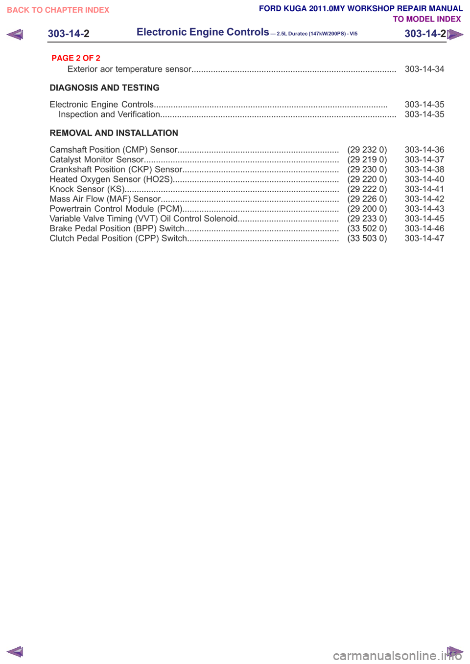
303-14-34
Exterior aor temperature sensor ........................................................................\
.............
DIAGNOSIS AND TESTING 303-14-35
Electronic Engine Controls ........................................................................\
.........................
303-14-35
Inspection and Verification ........................................................................\
..........................
REMOVAL AND INSTALLATION 303-14-36
(29 232 0)
Camshaft Position (CMP) Sensor ...................................................................
303-14-37
(29 219 0)
Catalyst Monitor Sensor ........................................................................\
.........
303-14-38
(29 230 0)
Crankshaft Position (CKP) Sensor .................................................................
303-14-40
(29 220 0)
Heated Oxygen Sensor (HO2S) .....................................................................
303-14-41
(29 222 0)
Knock Sensor (KS) ........................................................................\
.................
303-14-42
(29 226 0)
Mass Air Flow (MAF) Sensor ........................................................................\
..
303-14-43
(29 200 0)
Powertrain Control Module (PCM) .................................................................
303-14-45
(29 233 0)
Variable Valve Timing (VVT) Oil Control Solenoid ..........................................
303-14-46
(33 502 0)
Brake Pedal Position (BPP) Switch ................................................................
303-14-47
(33 503 0)
Clutch Pedal Position (CPP) Switch ...............................................................
303-14-2
Electronic Engine Controls— 2.5L Duratec (147kW/200PS) - VI5303-14-
2
.
TO MODEL INDEX
BACK TO CHAPTER INDEX
PAGE 2 OF 2
FORD KUGA 2011.0MY WORKSHOP REPAIR MANUAL
Page 1777 of 2057
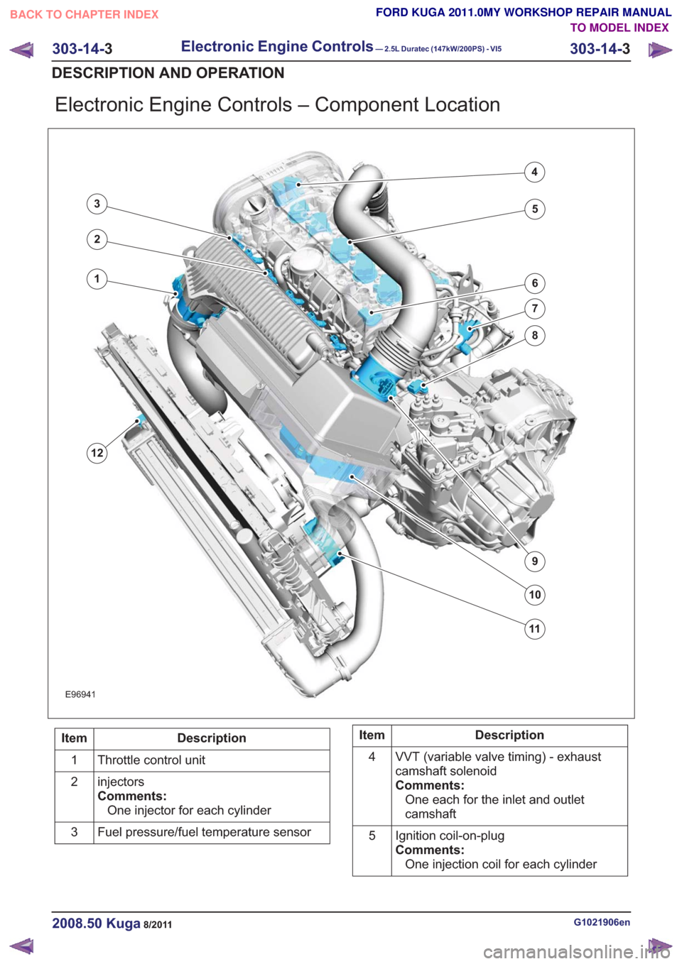
Electronic Engine Controls – Component Location
E96941
1
12
2
3
4
5
6
7
8
9
10
11
Description
Item
Throttle control unit
1
injectors
Comments:One injector for each cylinder
2
Fuel pressure/fuel temperature sensor
3Description
Item
VVT (variable valve timing) - exhaust
camshaft solenoid
Comments:One each for the inlet and outlet
camshaft
4
Ignition coil-on-plug
Comments:One injection coil for each cylinder
5
G1021906en2008.50 Kuga8/2011
303-14-
3
Electronic Engine Controls— 2.5L Duratec (147kW/200PS) - VI5303-14-
3
DESCRIPTION AND OPERATION
TO MODEL INDEX
BACK TO CHAPTER INDEX
FORD KUGA 2011.0MY WORKSHOP REPAIR MANUAL
Page 1784 of 2057
If one of the two APP sensors fails, then only a
proportion of the engine's power will be available
when accelerating. Top speed can nevertheless
be achieved.
If both of the APP sensors fail, the engine is
regulated to a defined speed following a plausibility
check after the BPP (brake pedal position) switch
and brake light switch have been actuated once.
The vehicle can then only be accelerated to a
defined speed.
In either case, a fault is saved in the error memory
of the PCM.
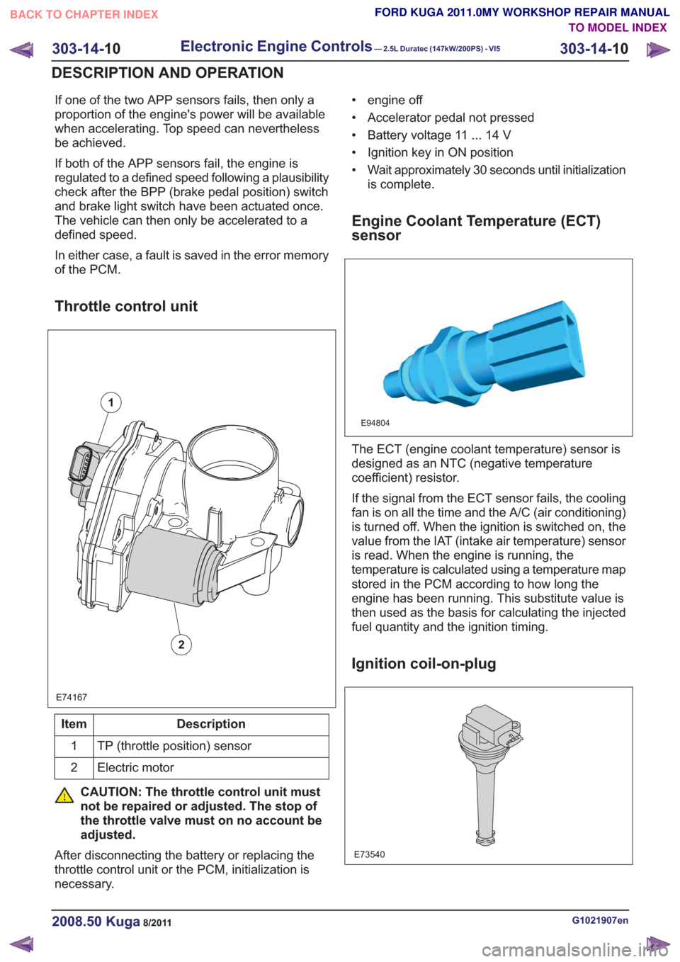
Throttle control unit
E74167
1
2
Description
Item
TP (throttle position) sensor
1
Electric motor
2
CAUTION: The throttle control unit must
not be repaired or adjusted. The stop of
the throttle valve must on no account be
adjusted.
After disconnecting the battery or replacing the
throttle control unit or the PCM, initialization is
necessary. • engine off
• Accelerator pedal not pressed
• Battery voltage 11 ... 14 V
• Ignition key in ON position
• Wait approximately 30 seconds until initialization
is complete.
Engine Coolant Temperature (ECT)
sensor
E94804
The ECT (engine coolant temperature) sensor is
designed as an NTC (negative temperature
coefficient) resistor.
If the signal from the ECT sensor fails, the cooling
fan is on all the time and the A/C (air conditioning)
is turned off. When the ignition is switched on, the
value from the IAT (intake air temperature) sensor
is read. When the engine is running, the
temperature is calculated using a temperature map
stored in the PCM according to how long the
engine has been running. This substitute value is
then used as the basis for calculating the injected
fuel quantity and the ignition timing.
Ignition coil-on-plug
E73540
G1021907en2008.50 Kuga8/2011
303-14- 10
Electronic Engine Controls— 2.5L Duratec (147kW/200PS) - VI5303-14-
10
DESCRIPTION AND OPERATION
TO MODEL INDEX
BACK TO CHAPTER INDEX
FORD KUGA 2011.0MY WORKSHOP REPAIR MANUAL
Page 1785 of 2057
The resistance in the ignition coil primary circuit
cannot be checked using a multimeter because
the power output stage is integrated into the ignition
coil.
G1021907en2008.50 Kuga8/2011
303-14-11
Electronic Engine Controls— 2.5L Duratec (147kW/200PS) - VI5303-14-
11
DESCRIPTION AND OPERATION
TO MODEL INDEX
BACK TO CHAPTER INDEX
FORD KUGA 2011.0MY WORKSHOP REPAIR MANUAL
Page 1788 of 2057
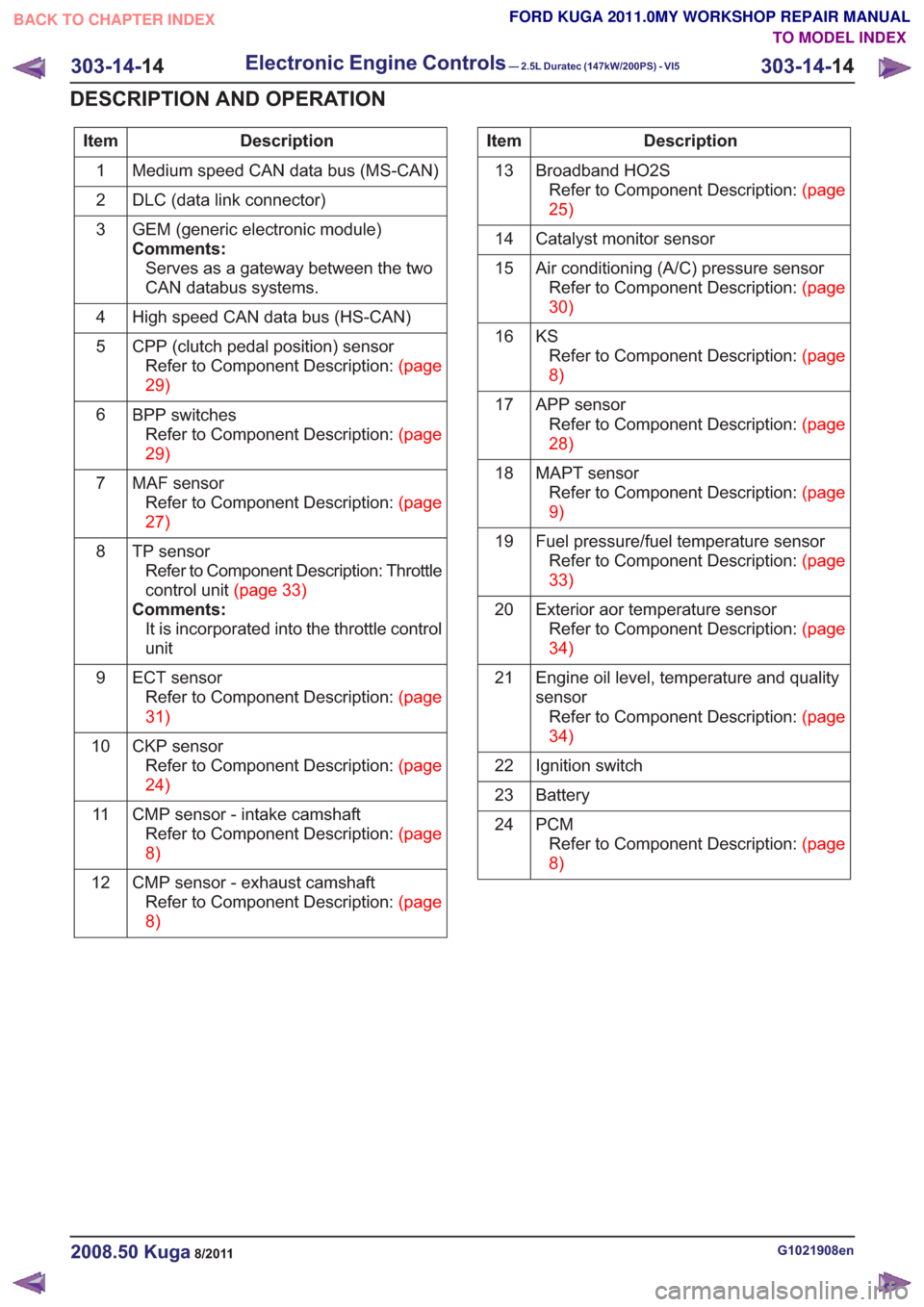
Description
Item
Medium speed CAN data bus (MS-CAN)
1
DLC (data link connector)
2
GEM (generic electronic module)
Comments:Serves as a gateway between the two
CAN databus systems.
3
High speed CAN data bus (HS-CAN)
4
CPP (clutch pedal position) sensorRefertoComponentDescription:(page
29)
5
BPP switchesRefertoComponentDescription:(page
29)
6
MAF sensorRefertoComponentDescription:(page
27)
7
TP sensorRefer to Component Description: Throttle
controlunit(page33)
Comments: It is incorporated into the throttle control
unit
8
ECT sensorRefertoComponentDescription:(page
31)
9
CKP sensorRefertoComponentDescription:(page
24)
10
CMP sensor - intake camshaftRefertoComponentDescription:(page
8)
11
CMP sensor - exhaust camshaftRefertoComponentDescription:(page
8)
12Description
Item
Broadband HO2SRefertoComponentDescription:(page
25)
13
Catalyst monitor sensor
14
Air conditioning (A/C) pressure sensorRefertoComponentDescription:(page
30)
15
KSRefertoComponentDescription:(page
8)
16
APP sensorRefertoComponentDescription:(page
28)
17
MAPT sensorRefertoComponentDescription:(page
9)
18
Fuel pressure/fuel temperature sensorRefertoComponentDescription:(page
33)
19
Exterior aor temperature sensorRefertoComponentDescription:(page
34)
20
Engine oil level, temperature and quality
sensorRefertoComponentDescription:(page
34)
21
Ignition switch
22
Battery
23
PCMRefertoComponentDescription:(page
8)
24
G1021908en2008.50 Kuga8/2011
303-14-
14
Electronic Engine Controls— 2.5L Duratec (147kW/200PS) - VI5303-14-
14
DESCRIPTION AND OPERATION
TO MODEL INDEX
BACK TO CHAPTER INDEX
FORD KUGA 2011.0MY WORKSHOP REPAIR MANUAL