Page 1726 of 2057
Action
Possible Sources
Symptom
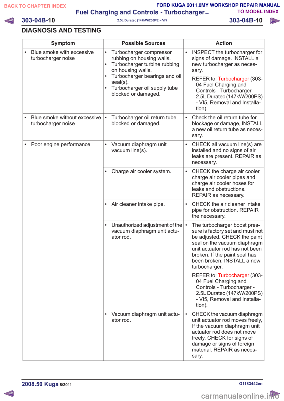
• INSPECT the turbocharger forsigns of damage. INSTALL a
new turbocharger as neces-
sary.
REFER to: Turbocharger (303-
04 Fuel Charging and
Controls - Turbocharger -
2.5L Duratec (147kW/200PS)
- VI5, Removal and Installa-
tion).
• Turbocharger compressor
rubbing on housing walls.
• Turbocharger turbine rubbing on housing walls.
• Turbocharger bearings and oil seal(s).
• Turbocharger oil supply tube blocked or damaged.
• Blue smoke with excessive
turbocharger noise
• Check the oil return tube forblockage or damage, INSTALL
a new oil return tube as neces-
sary.
• Turbocharger oil return tube
blocked or damaged.
• Blue smoke without excessive
turbocharger noise
• CHECK all vacuum line(s) areinstalled and no signs of air
leaks are present. REPAIR as
necessary.
• Vacuum diaphragm unit
vacuum line(s).
• Poor engine performance
• CHECK the charge air cooler,charge air cooler pipes and
charge air cooler hoses for
leaks and obstructions.
REPAIR as necessary.
• Charge air cooler system.
• CHECK the air cleaner intakepipe for obstruction. REPAIR
the necessary.
• Air cleaner intake pipe.
• The turbocharger boost pres-sure is factory set and must not
be adjusted. CHECK the paint
seal on the vacuum diaphragm
unit actuator rod has not been
broken. If the paint seal has
been broken, INSTALL a new
turbocharger.
REFER to: Turbocharger (303-
04 Fuel Charging and
Controls - Turbocharger -
2.5L Duratec (147kW/200PS)
- VI5, Removal and Installa-
tion).
• Unauthorized adjustment of the
vacuum diaphragm unit actu-
ator rod.
• CHECK the vacuum diaphragmunit actuator rod moves freely,
If the vacuum diaphragm unit
actuator rod does not move
freely. CHECK for signs of
damage or signs of foreign
material. REPAIR as neces-
sary.
• Vacuum diaphragm unit actu-
ator rod.
G1183442en2008.50 Kuga8/2011
303-04B- 10
Fuel Charging and Controls - Turbocharger
—
2.5L Duratec (147kW/200PS) - VI5
303-04B- 10
DIAGNOSIS AND TESTING
TO MODEL INDEX
BACK TO CHAPTER INDEX
FORD KUGA 2011.0MY WORKSHOP REPAIR MANUAL
Page 1727 of 2057
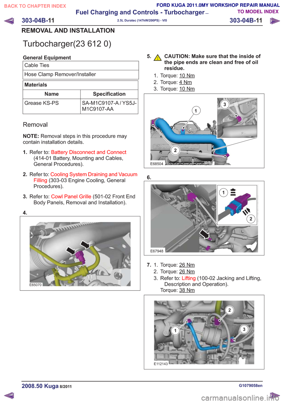
Turbocharger(23 612 0)
General EquipmentCable Ties
Hose Clamp Remover/Installer
Materials
Specification
Name
SA-M1C9107-A / YS5J-
M1C9107-AA
Grease KS-PS
Removal
NOTE:
Removal steps in this procedure may
contain installation details.
1. Refer to: Battery Disconnect and Connect
(414-01 Battery, Mounting and Cables,
General Procedures).
2. Refer to: Cooling System Draining and Vacuum
Filling (303-03 Engine Cooling, General
Procedures).
3. Refer to: Cowl Panel Grille (501-02 Front End
Body Panels, Removal and Installation).
4.
E65070
5. CAUTION: Make sure that the inside of the pipe ends are clean and free of oil
residue.
1. Torque: 10Nm
2. Torque: 4Nm
3. Torque: 10Nm
2
1
3
E68504
6.
E67948
2
1
7.Torque: 26Nm1.
2. Torque: 26
Nm
3. Refer to: Lifting(100-02 Jacking and Lifting,
Description and Operation).
Torque: 38
Nm
E112143
3
2
1
G1079058en2008.50 Kuga8/2011
303-04B- 11
Fuel Charging and Controls - Turbocharger
—
2.5L Duratec (147kW/200PS) - VI5
303-04B- 11
REMOVAL AND INSTALLATION
TO MODEL INDEX
BACK TO CHAPTER INDEX
FORD KUGA 2011.0MY WORKSHOP REPAIR MANUAL
Page 1728 of 2057
8.Torque: 24Nm
E112607
4
9. CAUTION: Make sure that the inside of
the pipe ends are clean and free of oil
residue.
10.Torque: 17Nm
E63819
12.
13.General Equipment: Cable Ties
14.Torque: 28Nm
E66825
G1079058en2008.50 Kuga8/2011
BACK TO CHAPTER INDEX
FORD KUGA 2011.0MY WORKSHOP REPAIR MANUAL
TO MODEL INDEX
E66726
TIE0014991
1
2
3
11. CAUTION: Make sure that the inside of
the pipe ends are clean and free of oil
residue.
Torque: 4Nm
E63820
303-04B- 12
Fuel Charging and Controls - Turbocharger
—
2.5L Duratec (147kW/200PS) - VI5
303-04B- 12
REMOVAL AND INSTALLATION
Page 1737 of 2057
Action
Possible Sources
Symptom
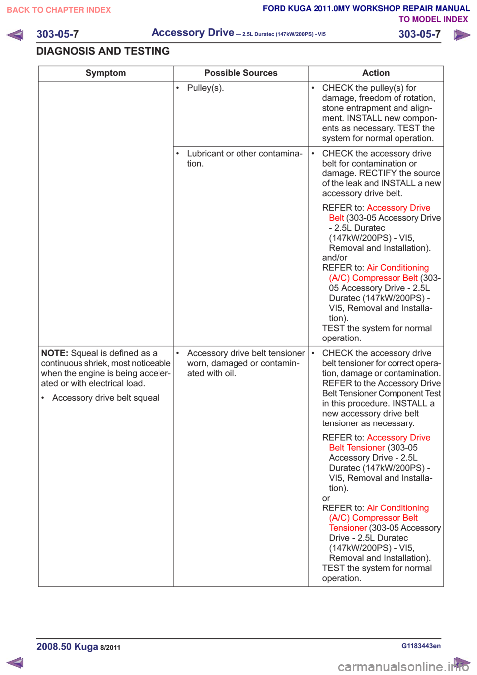
• CHECK the pulley(s) fordamage, freedom of rotation,
stone entrapment and align-
ment. INSTALL new compon-
ents as necessary. TEST the
system for normal operation.
• Pulley(s).
• CHECK the accessory drivebelt for contamination or
damage. RECTIFY the source
of the leak and INSTALL a new
accessory drive belt.
REFER to: Accessory Drive
Belt (303-05 Accessory Drive
- 2.5L Duratec
(147kW/200PS) - VI5,
Removal and Installation).
and/or
REFER to: Air Conditioning
(A/C) Compressor Belt (303-
05 Accessory Drive - 2.5L
Duratec (147kW/200PS) -
VI5, Removal and Installa-
tion).
TEST the system for normal
operation.
• Lubricant or other contamina-
tion.
• CHECK the accessory drivebelt tensioner for correct opera-
tion, damage or contamination.
REFER to the Accessory Drive
Belt Tensioner Component Test
in this procedure. INSTALL a
new accessory drive belt
tensioner as necessary.
REFER to: Accessory Drive
Belt Tensioner (303-05
Accessory Drive - 2.5L
Duratec (147kW/200PS) -
VI5, Removal and Installa-
tion).
or
REFER to: Air Conditioning
(A/C) Compressor Belt
Tensioner (303-05 Accessory
Drive - 2.5L Duratec
(147kW/200PS) - VI5,
Removal and Installation).
TEST the system for normal
operation.
• Accessory drive belt tensioner
worn, damaged or contamin-
ated with oil.
NOTE:
Squeal is defined as a
continuous shriek, most noticeable
when the engine is being acceler-
ated or with electrical load.
• Accessory drive belt squeal
G1183443en2008.50 Kuga8/2011
303-05- 7
Accessory Drive— 2.5L Duratec (147kW/200PS) - VI5303-05-
7
DIAGNOSIS AND TESTING
TO MODEL INDEX
BACK TO CHAPTER INDEX
FORD KUGA 2011.0MY WORKSHOP REPAIR MANUAL
Page 1756 of 2057
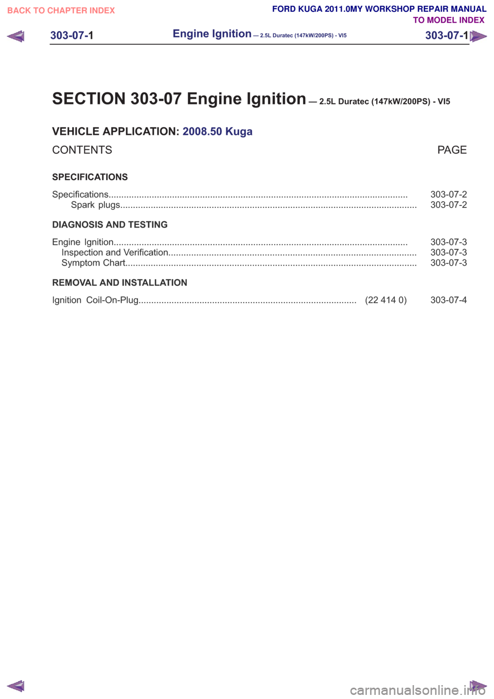
SECTION 303-07 Engine Ignition— 2.5L Duratec (147kW/200PS) - VI5
VEHICLE APPLICATION:2008.50 Kuga
PA G E
CONTENTS
SPECIFICATIONS
303-07-2
Specifications ........................................................................\
..............................................
303-07-2
Spark plugs ........................................................................\
.............................................
DIAGNOSIS AND TESTING 303-07-3
Engine Ignition ........................................................................\
............................................
303-07-3
Inspection and Verification ........................................................................\
..........................
303-07-3
Symptom Chart ........................................................................\
...........................................
REMOVAL AND INSTALLATION 303-07-4
(22 414 0)
Ignition Coil-On-Plug ........................................................................\
..............
303-07-1
Engine Ignition— 2.5L Duratec (147kW/200PS) - VI5303-07-
1
.
TO MODEL INDEX
BACK TO CHAPTER INDEX
FORD KUGA 2011.0MY WORKSHOP REPAIR MANUAL
Page 1758 of 2057
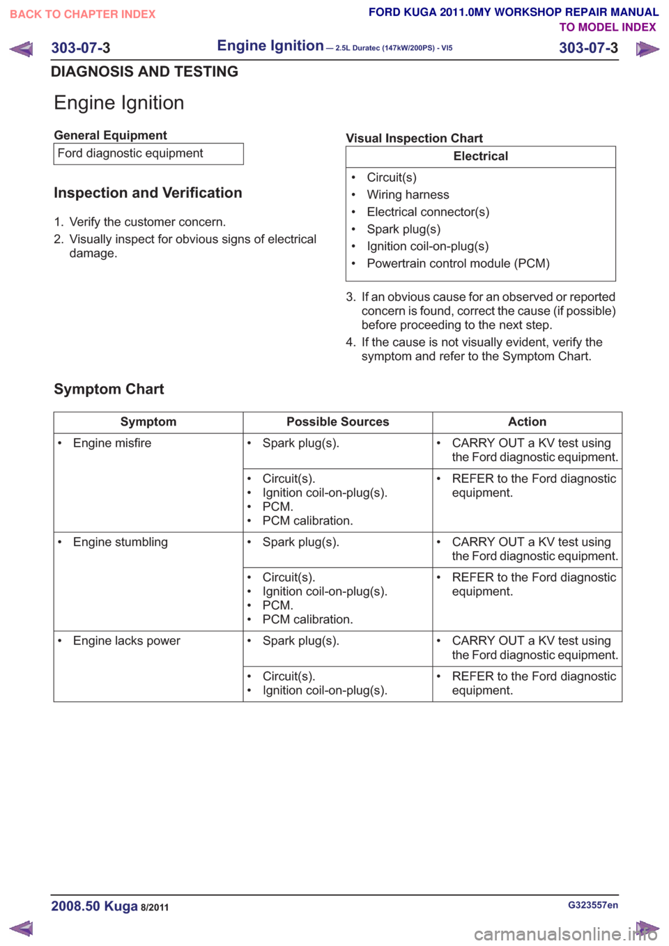
Engine Ignition
General EquipmentFord diagnostic equipment
Inspection and Verification
1. Verify the customer concern.
2. Visually inspect for obvious signs of electrical damage. Visual Inspection Chart
Electrical
• Circuit(s)
• Wiring harness
• Electrical connector(s)
• Spark plug(s)
• Ignition coil-on-plug(s)
• Powertrain control module (PCM)
3. If an obvious cause for an observed or reported concern is found, correct the cause (if possible)
before proceeding to the next step.
4. If the cause is not visually evident, verify the symptom and refer to the Symptom Chart.
Symptom Chart
Action
Possible Sources
Symptom
• CARRY OUT a KV test usingthe Ford diagnostic equipment.
• Spark plug(s).
• Engine misfire
• REFER to the Ford diagnosticequipment.
• Circuit(s).
• Ignition coil-on-plug(s).
•PCM.
• PCM calibration.
• CARRY OUT a KV test usingthe Ford diagnostic equipment.
• Spark plug(s).
• Engine stumbling
• REFER to the Ford diagnosticequipment.
• Circuit(s).
• Ignition coil-on-plug(s).
•PCM.
• PCM calibration.
• CARRY OUT a KV test usingthe Ford diagnostic equipment.
• Spark plug(s).
• Engine lacks power
• REFER to the Ford diagnosticequipment.
• Circuit(s).
• Ignition coil-on-plug(s).
G323557en2008.50 Kuga8/2011
303-07-
3
Engine Ignition— 2.5L Duratec (147kW/200PS) - VI5303-07-
3
DIAGNOSIS AND TESTING
TO MODEL INDEX
BACK TO CHAPTER INDEX
FORD KUGA 2011.0MY WORKSHOP REPAIR MANUAL
Page 1759 of 2057
Ignition Coil-On-Plug(22 414 0)
Removal
NOTE:Removal steps in this procedure may
contain installation details.
1. CAUTION: Make sure that the inside of the pipe ends are clean and free of oil
residue.
E65070
2. CAUTION: Make sure that the inside ofthe pipe ends are clean and free of oil
residue.
1. Torque: 10Nm
2. Torque: 4Nm
3. Torque: 10Nm
2
1
3
E68504
3.Torque: 10Nm
E113004
x8
4. Torque: 10Nm2.
1
22
E65075
Installation
1.To install, reverse the removal procedure.
G1165594en2008.50 Kuga8/2011
303-07- 4
Engine Ignition— 2.5L Duratec (147kW/200PS) - VI5303-07-
4
REMOVAL AND INSTALLATION
TO MODEL INDEX
BACK TO CHAPTER INDEX
FORD KUGA 2011.0MY WORKSHOP REPAIR MANUAL
Page 1762 of 2057
Description
Item
Intake manifold to turbocharger breather
hose
1
Crankcase vent oil separator to valve
cover hose
2
Crankcase vent oil separator to intake
manifold hose
3
Crankcase vent oil separator
4
G510285en2008.50 Kuga8/2011
303-08- 3
Engine Emission Control— 2.5L Duratec (147kW/200PS) - VI5303-08-
3
DESCRIPTION AND OPERATION
TO MODEL INDEX
BACK TO CHAPTER INDEX
FORD KUGA 2011.0MY WORKSHOP REPAIR MANUAL