2011 FORD KUGA oil
[x] Cancel search: oilPage 1807 of 2057
Description
Item
Coil-on-plug ignition coil
1
Spark plug connector
2
Low-voltage connection
3
Laminated soft-iron core
4Description
Item
Primary winding
5
Secondary winding
6
Spark plug
7
High-voltage connection via spring contact
8
In an ignition system with coil-on-plug ignition coils,
each cylinder is actuated individually and only once
per cycle (working stroke). The coil-on-plug ignition
coils are mounted directly on the spark plugs,
therefore no ignition cables are required between
the ignition coils and the spark plugs.
Each individual ignition coil is actuated on the
low-voltage side by the PCM. The power
end-stages are incorporated into the coil-on-plug
ignition coils. Only the actuating current for these
power end-stages is controlled by the PCM.
Fuel pressure/fuel temperature sensor
E73531
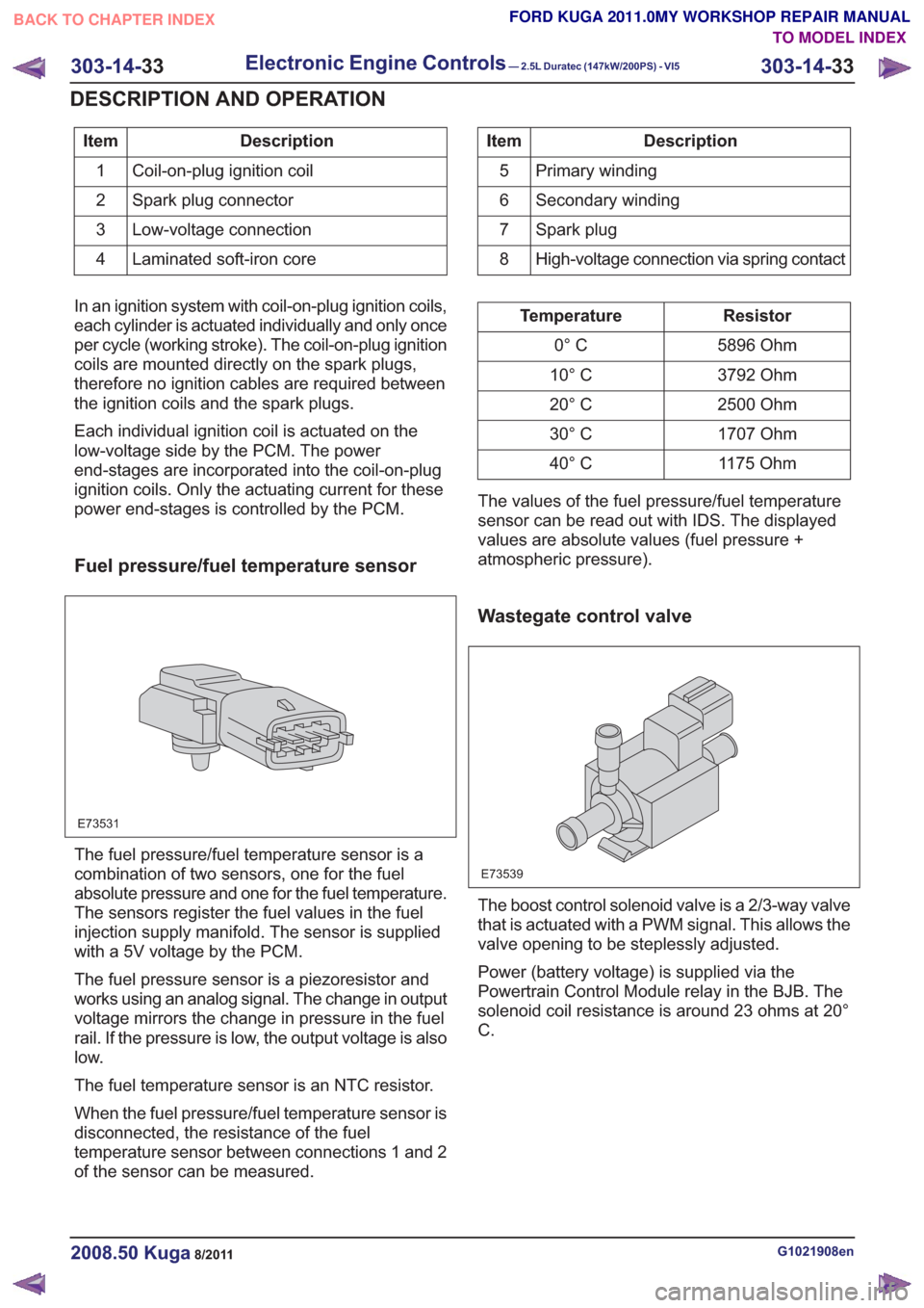
The fuel pressure/fuel temperature sensor is a
combination of two sensors, one for the fuel
absolute pressure and one for the fuel temperature.
The sensors register the fuel values in the fuel
injection supply manifold. The sensor is supplied
with a 5V voltage by the PCM.
The fuel pressure sensor is a piezoresistor and
works using an analog signal. The change in output
voltage mirrors the change in pressure in the fuel
rail. If the pressure is low, the output voltage is also
low.
The fuel temperature sensor is an NTC resistor.
When the fuel pressure/fuel temperature sensor is
disconnected, the resistance of the fuel
temperature sensor between connections 1 and 2
of the sensor can be measured.
Resistor
Temperature
5896 Ohm
0° C
3792 Ohm
10° C
2500 Ohm
20° C
1707 Ohm
30° C
1175 Ohm
40° C
The values of the fuel pressure/fuel temperature
sensor can be read out with IDS. The displayed
values are absolute values (fuel pressure +
atmospheric pressure).
Wastegate control valve
E73539
The boost control solenoid valve is a 2/3-way valve
that is actuated with a PWM signal. This allows the
valve opening to be steplessly adjusted.
Power (battery voltage) is supplied via the
Powertrain Control Module relay in the BJB. The
solenoid coil resistance is around 23 ohms at 20°
C.
G1021908en2008.50 Kuga8/2011
303-14- 33
Electronic Engine Controls— 2.5L Duratec (147kW/200PS) - VI5303-14-
33
DESCRIPTION AND OPERATION
TO MODEL INDEX
BACK TO CHAPTER INDEX
FORD KUGA 2011.0MY WORKSHOP REPAIR MANUAL
Page 1808 of 2057
Engine oil level, temperature and quality
sensor
E95312
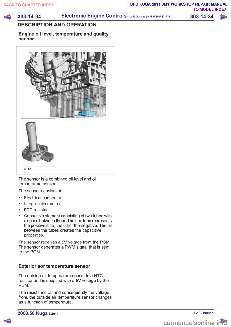
The sensor is a combined oil level and oil
temperature sensor.
The sensor consists of:
• Electrical connector
• Integral electronics
• PTC resistor
• Capacitive element consisting of two tubes witha space between them. The one tube represents
the positive side, the other the negative. The oil
between the tubes creates the capacitive
properties.
The sensor receives a 5V voltage from the PCM.
The sensor generates a PWM signal that is sent
to the PCM.
Exterior aor temperature sensor
The outside air temperature sensor is a NTC
resistor and is supplied with a 5V voltage by the
PCM.
The resistance of, and consequently the voltage
from, the outside air temperature sensor changes
as a function of temperature.
G1021908en2008.50 Kuga8/2011
303-14- 34
Electronic Engine Controls— 2.5L Duratec (147kW/200PS) - VI5303-14-
34
DESCRIPTION AND OPERATION
TO MODEL INDEX
BACK TO CHAPTER INDEX
FORD KUGA 2011.0MY WORKSHOP REPAIR MANUAL
Page 1810 of 2057
Camshaft Position (CMP) Sensor(29 232 0)
Removal
NOTE:Removal steps in this procedure may
contain installation details.
1. Refer to: Battery Disconnect and Connect
(414-01 Battery, Mounting and Cables,
General Procedures).
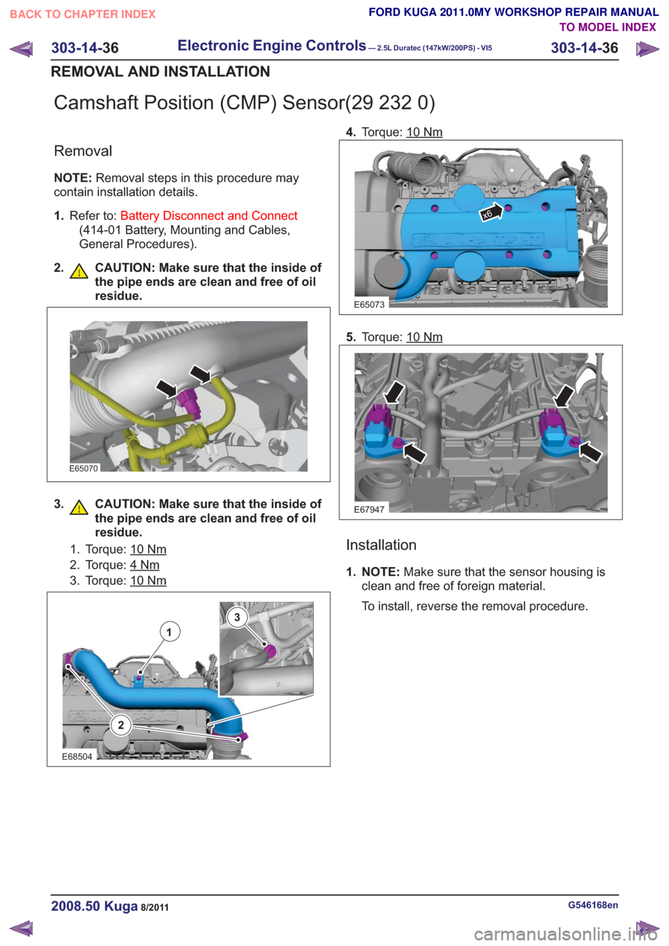
2. CAUTION: Make sure that the inside of the pipe ends are clean and free of oil
residue.
E65070
3. CAUTION: Make sure that the inside ofthe pipe ends are clean and free of oil
residue.
1. Torque: 10Nm
2. Torque: 4Nm
3. Torque: 10Nm
2
1
3
E68504
4.Torque: 10Nm
E65073
x6
5.Torque: 10Nm
E67947
Installation
1. NOTE: Make sure that the sensor housing is
clean and free of foreign material.
To install, reverse the removal procedure.
G546168en2008.50 Kuga8/2011
303-14- 36
Electronic Engine Controls— 2.5L Duratec (147kW/200PS) - VI5303-14-
36
REMOVAL AND INSTALLATION
TO MODEL INDEX
BACK TO CHAPTER INDEX
FORD KUGA 2011.0MY WORKSHOP REPAIR MANUAL
Page 1812 of 2057
Crankshaft Position (CKP) Sensor(29 230 0)
Removal
NOTE:Removal steps in this procedure may
contain installation details.
1. Refer to: Lifting(100-02 Jacking and Lifting,
Description and Operation).
2.
x7x7
E86012
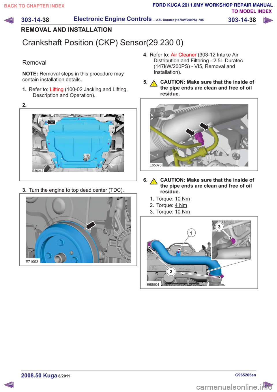
3. Turn the engine to top dead center (TDC).
E71093
4.Refer to: Air Cleaner (303-12 Intake Air
Distribution and Filtering - 2.5L Duratec
(147kW/200PS) - VI5, Removal and
Installation).
5. CAUTION: Make sure that the inside of the pipe ends are clean and free of oil
residue.
E65070
6. CAUTION: Make sure that the inside ofthe pipe ends are clean and free of oil
residue.
1. Torque: 10Nm
2. Torque: 4Nm
3. Torque: 10Nm
2
1
3
E68504
G965265en2008.50 Kuga8/2011
303-14- 38
Electronic Engine Controls— 2.5L Duratec (147kW/200PS) - VI5303-14-
38
REMOVAL AND INSTALLATION
TO MODEL INDEX
BACK TO CHAPTER INDEX
FORD KUGA 2011.0MY WORKSHOP REPAIR MANUAL
Page 1814 of 2057
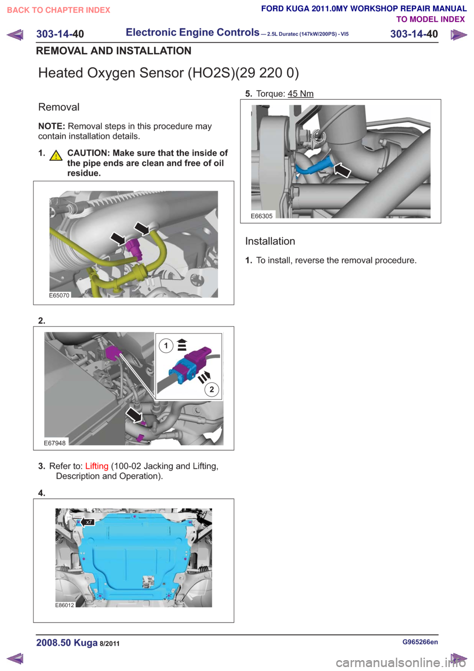
Heated Oxygen Sensor (HO2S)(29 220 0)
Removal
NOTE:Removal steps in this procedure may
contain installation details.
1. CAUTION: Make sure that the inside of the pipe ends are clean and free of oil
residue.
E65070
2.
E67948
2
1
3.Refer to: Lifting(100-02 Jacking and Lifting,
Description and Operation).
4.
x7x7
E86012
5. Torque: 45Nm
E66305
Installation
1.To install, reverse the removal procedure.
G965266en2008.50 Kuga8/2011
303-14- 40
Electronic Engine Controls— 2.5L Duratec (147kW/200PS) - VI5303-14-
40
REMOVAL AND INSTALLATION
TO MODEL INDEX
BACK TO CHAPTER INDEX
FORD KUGA 2011.0MY WORKSHOP REPAIR MANUAL
Page 1819 of 2057
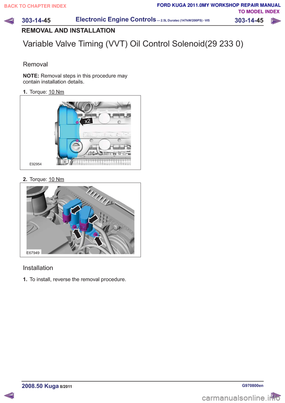
Variable Valve Timing (VVT) Oil Control Solenoid(29 233 0)
Removal
NOTE:Removal steps in this procedure may
contain installation details.
1. Torque: 10
Nm
x2x2
E92954
2.Torque: 10Nm
E67949
Installation
1.To install, reverse the removal procedure.
G970800en2008.50 Kuga8/2011
303-14- 45
Electronic Engine Controls— 2.5L Duratec (147kW/200PS) - VI5303-14-
45
REMOVAL AND INSTALLATION
TO MODEL INDEX
BACK TO CHAPTER INDEX
FORD KUGA 2011.0MY WORKSHOP REPAIR MANUAL
Page 1823 of 2057
307-01-29
Automatic transmission, selector lever in position "D". ...................................................
307-01-29
Sport mode, selector lever in position "S" .......................................................................
307-01-29
Changing gear in select-shift mode........................................................................\
........
307-01-30
Selector lever from 'N' to 'R' position ........................................................................\
......
307-01-30
Self-test and Diagnosis ........................................................................\
...........................
307-01-30
Temperature controlled torque converter lockup ............................................................
307-01-30
Slip locking ........................................................................\
..............................................
307-01-30
Hill climbing ........................................................................\
.............................................
307-01-31
Downhill driving ........................................................................\
.......................................
307-01-31
Hill-hold function ........................................................................\
.....................................
307-01-31
Altitude correction ........................................................................\
...................................
307-01-31
Selector lever lock ........................................................................\
..................................
307-01-31
Shifting from P into another transmission range .............................................................
307-01-31
Shifting from N into another transmission range .............................................................
307-01-31
Power flow through the transmission ........................................................................\
......
307-01-31
Clutches and brakes ........................................................................\
...............................
307-01-33
Position P (park) ........................................................................\
.....................................
307-01-34
Position N (neutral) ........................................................................\
.................................
307-01-35
Position D, 1st gear........................................................................\
................................
307-01-36
Position D, 2nd gear ........................................................................\
...............................
307-01-37
Position D, 3rd gear ........................................................................\
................................
307-01-38
Position D, 4th gear ........................................................................\
................................
307-01-39
Position D, 5th gear ........................................................................\
................................
307-01-40
Position R (reverse) ........................................................................\
................................
307-01-41
Service instructions ........................................................................\
.................................
307-01-41
Towing procedure ........................................................................\
...................................
307-01-42
Reset adaptation data ........................................................................\
.............................
307-01-42
Limp home mode ........................................................................\
....................................
307-01-42
Component Description ........................................................................\
..............................
Tasks of the electronic components ........................................................................\
........
307-01-44
Input signals ........................................................................\
............................................
307-01-45
Output signals ........................................................................\
.........................................
Control valve assembly ........................................................................\
...........................
Shift solenoids S1 - S5 ........................................................................\
...........................
PWM-
solenoid valve – TCC (SLU) ........................................................................\
........
PWM solenoid valve – shift pressure (SLS) ...................................................................
PWM solenoid valve for main line pressure (SLT) ..........................................................
307-01-52
Installation position ........................................................................\
.................................
Operation ........................................................................\
................................................
Selector lever with integrated select-shift switch module ...............................................
Oil pump ........................................................................\
..................................................
Torque converter with TCC ........................................................................\
.....................
The TSS sensor ........................................................................\
......................................
The OSS sensor ........................................................................\
.....................................
The TFT sensor ........................................................................\
......................................
The TR sensor ........................................................................\
........................................
GENERAL PROCEDURES
T ransmission Fluid Level Check ........................................................................\
.................
307-01-63
T ransmission Fluid Drain and Refill ........................................................................\
............
REMOVAL AND INSTALLATION 307-01-67
Halfshaft Seal LH ........................................................................\
........................................
307-01-68
Halfshaft Seal RH........................................................................\
.......................................
307-01-69
Main Control Valve Body ........................................................................\
............................
307-01-2
Automatic Transmission/Transaxle
— Vehicles With:
5-Speed Automatic Transaxle - AW55 AWD
307-01- 2
.
TO MODEL INDEX
BACK TO CHAPTER INDEX
307-01-42
307-01-49
307-01-52 307-01-47
307-01-45
307-01-50
307-01-51
307-01-53
307-01-55
307-01-54
307-01-56
307-01-57
307-01-58
307-01-61 307-01-60
PAGE 2 OF 3 FORD KUGA 2011.0MY WORKSHOP REPAIR MANUAL
Page 1875 of 2057

Overview of the select-shift switch module
E112331
The select-shift switch module is located on the
upper trim of the selector lever unit. The module
is supplied with power by the TCM.
It uses the LIN databus to interact with the TCM,
for instance to activate the selector lever position
display.
It allows the automatic transmission gears to be
changed up and down manually via the signals of
the Hall sensors.
The select-shift switch module detects the selector
lever position 'P' and 'S' via the integrated selector
lever position sensors (Hall sensors).
A cable leading from the TCM passes directly to
the select-shift switch module and is used to control
the solenoid of the selector lever lock. The
switching solenoid receives its voltage supply
directly from the module.
In the event of a fault, a signal is transmitted to the
TCM where all DTCs are stored.
Oil pump
E68097
1
2
3
45
Description
Item
Fluid pump rotor, outer
1
Fluid pump rotor, inner
2
G1163605en2008.50 Kuga8/2011
307-01- 54
Automatic Transmission/Transaxle
— Vehicles With:
5-Speed Automatic Transaxle - AW55 AWD
307-01- 54
DESCRIPTION AND OPERATION
TO MODEL INDEX
BACK TO CHAPTER INDEX
FORD KUGA 2011.0MY WORKSHOP REPAIR MANUAL