2011 FORD KUGA seats
[x] Cancel search: seatsPage 82 of 2057

sometimes noticed in the steering wheel/column,
seats, front floor panel, front door trim panel or
front end sheet metal. It is a low frequency
vibration (around 9-15 cycles per second). It
may or may not be increased by applying the
brakes lightly. REFER to Idle
Boom/Shake/Vibration in the Driveline Noise
and Vibration Symptom Chart.
3. High Speed: A vibration is felt in the front floor panel or seats with no visible shake, but with
an accompanying sound or rumble, buzz, hum,
drone or booming noise. Coast with the clutch
pedal depressed (manual transmission) or shift
control selector lever in "N" (NEUTRAL)
(automatic transmission) and engine idling. If
vibration is still evident, it may be related to
wheels, tires, front brake discs, wheel hubs or
front wheel bearings. REFER to Shake and
Vibration While Driving in the Driveline Noise
and Vibration Symptom Chart.
4. Engine rpm Sensitive: A vibration is felt whenever the engine reaches a particular rpm.
It will disappear in neutral coasts. The vibration
can be duplicated by operating the engine at
the problem rpm while the vehicle is stationary.
It can be caused by any component, from the
accessory drive belt to the clutch or torque
converter which turns at engine speed when the
vehicle is stopped. REFER to Shake and
Vibration While Driving in the Driveline Noise
and Vibration Symptom Chart.
5. Noise and Vibration While Turning: Clicking, popping or grinding noises may be due to the
following:
• worn, damaged or incorrectly installed front wheel bearing.
• damaged powertrain/drivetrain mounts.
Road Conditions
An experienced technician will always establish a
route that will be used for all NVH diagnosis road
tests. The road selected should be reasonably
smooth, level and free of undulations (unless a
particular condition needs to be identified). A
smooth asphalt road that allows driving over a
range of speeds is best. Gravel or bumpy roads
are unsuitable because of the additional road noise
produced. Once the route is established and consistently used, the road noise variable is
eliminated from the test results.
NOTE:
Some concerns may be apparent only on
smooth asphalt roads.
If a customer complains of a noise or vibration on
a particular road and only on a particular road, the
source of the concern may be the road surface. If
possible, try to test the vehicle on the same type
of road.
Vehicle Preparation
Carry out a thorough visual inspection of the
vehicle before carrying out the road test. Note
anything which is unusual. Do not repair or adjust
any condition until the road test is carried out,
unless the vehicle is inoperative or the condition
could pose a hazard to the technician. After
verifying that the condition has been corrected,
make sure all components removed have been
installed.
Power Steering Conditions
Check for the noise in the following conditions to
verify the customer concern.
• Check for the noise in several temperature conditions.
• Is the noise from when the vehicle was new?
• Can the noise be repeated constantly or is it random?
• Check the condition of the vehicle age, mileage and service record.
• Interview the customer to find the operating condition in which the noise will occur. Test the
vehicle based on the detail(s) from the customer
interview.
• Follow the power steering operation noise condition tables below, to find which condition
the noise will occur.
Power Steering Operation Noise Check
Step 1: Check for NVH concerns from non-steering
components, which may sound like noises coming
from the steering system.
G37349en2008.50 Kuga8/2011
100-04- 4
Noise, Vibration and Harshness
100-04- 4
DIAGNOSIS AND TESTING
TO MODEL INDEX
BACK TO CHAPTER INDEX
FORD KUGA 2011.0MY WORKSHOP REPAIR MANUAL
Page 1159 of 2057

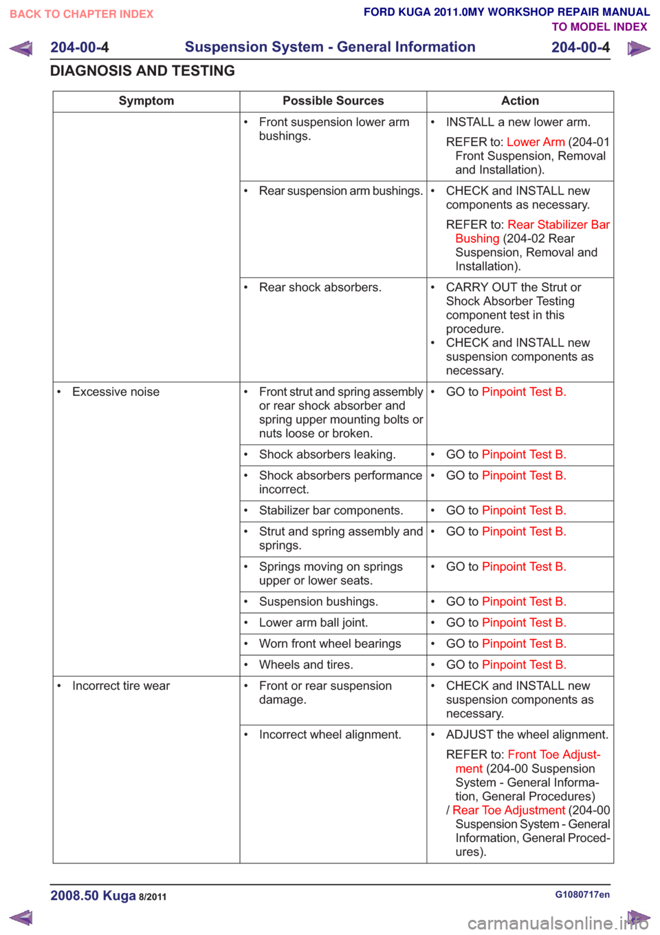
Action
Possible Sources
Symptom
• INSTALL a new lower arm.REFER to: Lower Arm (204-01
Front Suspension, Removal
and Installation).
• Front suspension lower arm
bushings.
• CHECK and INSTALL newcomponents as necessary.
REFER to: Rear Stabilizer Bar
Bushing (204-02 Rear
Suspension, Removal and
Installation).
• Rear suspension arm bushings.
• CARRY OUT the Strut orShock Absorber Testing
component test in this
procedure.
• CHECK and INSTALL new suspension components as
necessary.
• Rear shock absorbers.
• GO toPinpoint Test B.
• Front strut and spring assembly
or rear shock absorber and
spring upper mounting bolts or
nuts loose or broken.
• Excessive noise
• GO toPinpoint Test B.
• Shock absorbers leaking.
• GO toPinpoint Test B.
• Shock absorbers performance
incorrect.
• GO toPinpoint Test B.
• Stabilizer bar components.
• GO toPinpoint Test B.
• Strut and spring assembly and
springs.
• GO toPinpoint Test B.
• Springs moving on springs
upper or lower seats.
• GO toPinpoint Test B.
• Suspension bushings.
• GO toPinpoint Test B.
• Lower arm ball joint.
• GO toPinpoint Test B.
• Worn front wheel bearings
• GO toPinpoint Test B.
• Wheels and tires.
• CHECK and INSTALL newsuspension components as
necessary.
• Front or rear suspension
damage.
• Incorrect tire wear
• ADJUST the wheel alignment.REFER to: Front Toe Adjust-
ment (204-00 Suspension
System - General Informa-
tion, General Procedures)
/ Rear Toe Adjustment (204-00
Suspension System - General
Information, General Proced-
ures).
• Incorrect wheel alignment.
G1080717en2008.50 Kuga8/2011
204-00-
4
Suspension System - General Information
204-00- 4
DIAGNOSIS AND TESTING
TO MODEL INDEX
BACK TO CHAPTER INDEX
FORD KUGA 2011.0MY WORKSHOP REPAIR MANUAL
Page 1537 of 2057

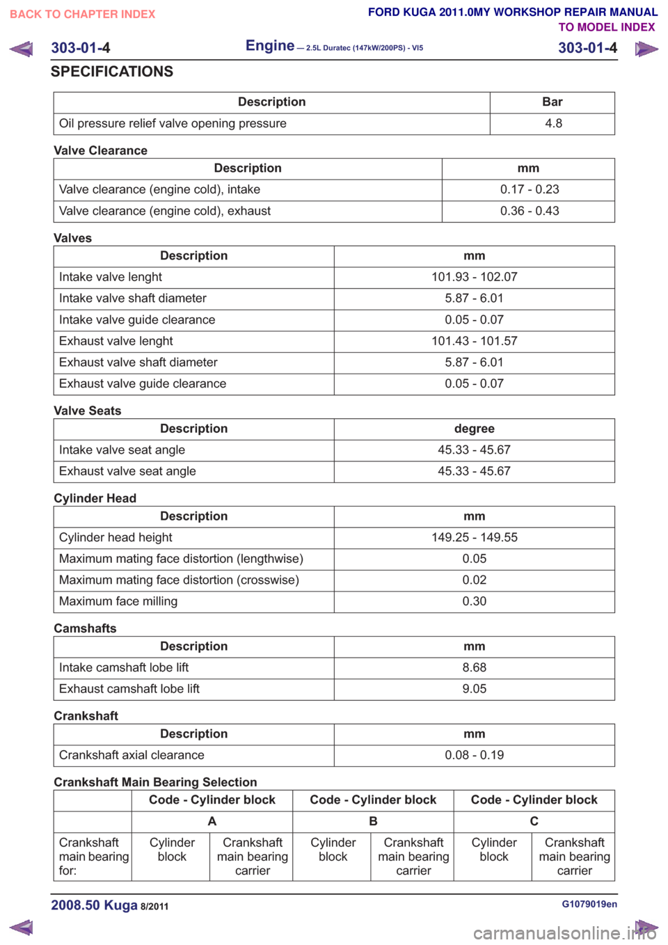
Bar
Description
4.8
Oil pressure relief valve opening pressure
Valve Clearance
mm
Description
0.17 - 0.23
Valve clearance (engine cold), intake
0.36 - 0.43
Valve clearance (engine cold), exhaust
Valves
mm
Description
101.93 - 102.07
Intake valve lenght
5.87 - 6.01
Intake valve shaft diameter
0.05 - 0.07
Intake valve guide clearance
101.43 - 101.57
Exhaust valve lenght
5.87 - 6.01
Exhaust valve shaft diameter
0.05 - 0.07
Exhaust valve guide clearance
Valve Seats
degree
Description
45.33 - 45.67
Intake valve seat angle
45.33 - 45.67
Exhaust valve seat angle
Cylinder Head
mm
Description
149.25 - 149.55
Cylinder head height
0.05
Maximum mating face distortion (lengthwise)
0.02
Maximum mating face distortion (crosswise)
0.30
Maximum face milling
Camshafts
mm
Description
8.68
Intake camshaft lobe lift
9.05
Exhaust camshaft lobe lift
Crankshaft
mm
Description
0.08 - 0.19
Crankshaft axial clearance
Crankshaft Main Bearing Selection
Code - Cylinder block
Code - Cylinder block
Code - Cylinder block
C
B
A
Crankshaft
main bearing carrier
Cylinder
block
Crankshaft
main bearing carrier
Cylinder
block
Crankshaft
main bearing carrier
Cylinder
block
Crankshaft
main bearing
for:
G1079019en2008.50 Kuga8/2011
303-01-
4
Engine— 2.5L Duratec (147kW/200PS) - VI5303-01-
4
SPECIFICATIONS
TO MODEL INDEX
BACK TO CHAPTER INDEX
FORD KUGA 2011.0MY WORKSHOP REPAIR MANUAL