2011 FORD KUGA jump cable
[x] Cancel search: jump cablePage 7 of 2057

100-00-48
Lubricants and Greases ........................................................................\
.............................
100-00-48
Transmission Fluids ........................................................................\
....................................
100-00-49
Noise ........................................................................\
..........................................................
100-00-49
Noise Insulation Materials ........................................................................\
..........................
100-00-49
O-Rings (Fluoroelastomer) ........................................................................\
.........................
100-00-49
Paints ........................................................................\
..........................................................
100-00-50
Pressurized Equipment ........................................................................\
..............................
100-00-50
Solder ........................................................................\
.........................................................
100-00-50
Solvents ........................................................................\
......................................................
100-00-50
Sound Insulation ........................................................................\
.........................................
100-00-50
Suspended Loads ........................................................................\
.......................................
100-00-50
Transmission Brake Bands ........................................................................\
.........................
100-00-50
Underseal ........................................................................\
...................................................
100-00-50
Viton ........................................................................\
............................................................
100-00-51
Welding ........................................................................\
.......................................................
100-00-52
Warning Symbols on Vehicles ........................................................................\
....................
100-00-53
White Spirit ........................................................................\
.................................................
100-00-54
Standard Workshop Practices ........................................................................\
....................
100-00-54
Vehicle in Workshop ........................................................................\
...................................
100-00-54
Towing the Vehicle ........................................................................\
......................................
100-00-54
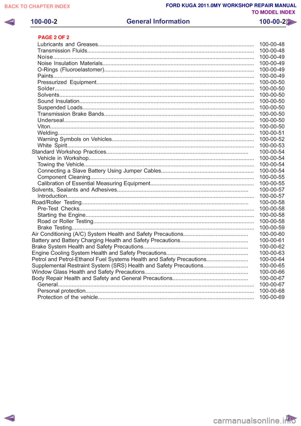
Connecting a Slave Battery Using Jumper Cables ............................................................
100-00-55
Component Cleaning ........................................................................\
..................................
100-00-55
Calibration of Essential Measuring Equipment ...................................................................
100-00-57
Solvents, Sealants and Adhesives ........................................................................\
.............
100-00-57
Introduction ........................................................................\
.................................................
100-00-58
Road/Roller Testing ........................................................................\
....................................
100-00-58
Pre-Test Checks ........................................................................\
.........................................
100-00-58
Starting the Engine ........................................................................\
.....................................
100-00-58
Road or Roller Testing ........................................................................\
................................
100-00-59
Brake Testing ........................................................................\
..............................................
100-00-60
Air Conditioning (A/C) System Health and Safety Precautions ..........................................
100-00-61
Battery and Battery Charging Health and Safety Precautions ............................................
100-00-62
Brake System Health and Safety Precautions
....................................................................
100-00-63
Engine
Cooling System Health and Safety Precautions .....................................................
100-00-64
Petrol and Petrol-Ethanol Fuel Systems Health and Safety Precautions ...........................
100-00-65
Supplemental Restraint System (SRS) Health and Safety Precautions .............................
100-00-66
Window Glass Health and Safety Precautions ...................................................................
100-00-67
Body Repair Health and Safety and General Precautions .................................................
100-00-67
General ........................................................................\
.......................................................
100-00-68
Personal protection ........................................................................\
.....................................
100-00-69
Protection of the vehicle ........................................................................\
.............................
100-00-2
General Information
100-00- 2
.
TO MODEL INDEX
BACK TO CHAPTER INDEX
PAGE 2 OF 2 FORD KUGA 2011.0MY WORKSHOP REPAIR MANUAL
Page 60 of 2057

Standard Workshop Practices
Vehicle in Workshop
When working on a vehicle in the workshop always
make sure that:
– the parking brake is applied or the wheels aresecurely chocked to prevent the vehicle moving
forwards or backwards.
– the key is removed from key operated hood locks before any work is carried out around the
front of the vehicle.
– if the engine is to be run, there is adequate ventilation, or an extraction hose to remove
exhaust fumes.
– there is adequate room to raise the vehicle and remove the wheels, if necessary.
– fender covers are always fitted if any work is to be carried out in the engine compartment.
– the battery is disconnected if working on the engine, underneath the vehicle, or if the vehicle
is raised.
CAUTION: When electric arc welding on a
vehicle, always disconnect the generator
wiring to prevent the possibility of a surge
of current causing damage to the internal
components of the generator.
– if using welding equipment on the vehicle, a suitable fire extinguisher is readily available.
Towing the Vehicle
WARNING: When the vehicle is being
towed, the ignition switch must be in
position II (steering lock released and
warning lamps illuminated). Only then will
the steering, turn signal lamps, horn and
stop lamps be operational. Failure to follow
these instructions may result in personal
injury.
NOTE: The removable towing eye (if equipped),
has a left-hand thread and must be fully tightened
before towing can commence.
When towing is necessary, the vehicle towing eyes
should be used. The rope must be securely
fastened to the towing eyes and must also be
attached to the other vehicle such that the rope will
not foul the bodywork.
When a vehicle with automatic transmission is
towed, the gear selector must be in position N (Neutral). Never tow a vehicle with automatic
transmission at a speed greater than 30 mph (50
km/h) or for a distance greater than 30 miles (50
km). If it is necessary to tow the vehicle a greater
distance, the drive wheels must be lifted clear off
the ground.
Alternatively the vehicle can be transported on a
low loader or a trailer.
Connecting a Slave Battery Using
Jumper Cables
WARNING: If the slave battery has recently
been charged and is gassing, cover the
vent plugs or covers with a damp cloth to
reduce the risk of explosion should arcing
occur when connecting the jumper cables.
Failure to follow these instructions may
result in personal injury.
CAUTIONS:
A discharged battery condition may have
been caused by an electrical short circuit.
If this condition exists there will be an
apparently live circuit on the vehicle even
when all normal circuits are switched off.
This can cause arcing when the jumper
cables are connected.
While it is not recommended that the
vehicle is jump started, it is recognized
that this may occasionally be the only
practical way to mobilize a vehicle. In such
an instance, the discharged battery must
be recharged immediately after jump
starting to avoid permanent damage.
– Always make sure that the jumper cables are adequate for the task. Heavy duty cables must
be used.
– Always make sure that the slave battery is of the same voltage as the vehicle battery. The
batteries must be connected in parallel.
– Always make sure that switched electric circuits are switched off before connecting jumper
cables. This reduces the risk of arcing occurring
when the final connection is made.
G17373en2008.50 Kuga8/2011
100-00- 54
General Information
100-00- 54
DESCRIPTION AND OPERATION
TO MODEL INDEX
BACK TO CHAPTER INDEX
FORD KUGA 2011.0MY WORKSHOP REPAIR MANUAL
Page 62 of 2057

TIM0103001
WARNING: Make sure that the ends of the
jumper cables do not touch each other or
ground against the vehicle body at any
time while the cables are attached to the
battery. A fully charged battery, if shorted
through jumper cables, can discharge at
a rate well above 1000 amps causing
violent arcing and very rapid heating of the
jumper cables and terminals, and can even
cause the battery to explode. Failure to
follow these instructions may result in
personal injury.
Always connect the jumper cables in the following
sequence:
– Slave battery positive first and then vehicle battery positive.
– Slave battery negative next and then vehicle ground at least 12 inches (300 mm) from the
battery terminal, for example engine lifting eye.
Always reduce the engine speed to idle before
disconnecting the jumper cables.
Before removing the jumper cables from the vehicle
that had the discharged battery, switch on the
heater blower (high) or the heated rear window, to
reduce the voltage peak when the cables are
removed.
Always disconnect the jumper cables in the reverse
order to the connecting sequence and do not short
the ends of the cables.
Do not rely on the generator to restore a
discharged battery. For a generator to recharge a
battery, it would take in excess of eight hours
continuous driving with no additional loads placed
on the battery.
Component Cleaning
To prevent the ingress of dirt, accumulations of
loose dirt and greasy deposits should be removed before disconnecting or dismantling components
or assemblies.
Components should be thoroughly cleaned before
inspection prior to reassembly.
Cleaning Methods:
– Dry cleaning.
– Removal of loose dirt with soft or cable brushes.
– Scraping dirt off with a piece of metal or wood.
– Wiping off with a rag.
WARNING: Wear eye protection when
cleaning vehicle components with
compressed air, a steam cleaner or a
power washer. Failure to follow this
instruction may result in personal injury.
CAUTIONS:
Compressed air is sometimes 'wet' so use
with caution, especially on hydraulic
systems.
To prevent damage to the electrical
connectors in the engine compartment, do
not use a steam cleaner or a power washer
to clean the engine compartment.
– Blowing dirt off with compressed air.
– Removal of dry dust using vacuum equipment. This method must always be used to remove
friction lining material dust (asbestos particles).
– Steam cleaning.
WARNING: Most solvents require careful
handling and some are harmful. Refer to
Health and Safety Precautions and to the
manufacturers literature for the relevant
safety precautions. Failure to follow these
instructions may result in personal injury.
Various solvents are available which are suitable
for component cleaning. Some components, such
as brake hydraulic parts and electrical assemblies
should be cleaned only with recommended solvents
— refer to Solvents, Sealers and Adhesives or to
the section of the manual relevant to the
component.
Calibration of Essential Measuring
Equipment
WARNING: Equipment, which requires
regular calibration, must be calibrated in
accordance with the manufacturers
G17373en2008.50 Kuga8/2011
100-00- 55
General Information
100-00- 55
DESCRIPTION AND OPERATION
TO MODEL INDEX
BACK TO CHAPTER INDEX
FORD KUGA 2011.0MY WORKSHOP REPAIR MANUAL
Page 266 of 2057

• Surface charge removal procedure
• Dynamic Response procedure for refined
decisiveness on battery diagnostics
• Upgradeable by SD card
• Export data feature to send data to infra red printer
• Voltmeter function
• Date and time indication with every test
• 23 languages included within the battery tester
Using the Midtronics EXP-1050 battery
tester
• Disconnect the battery ground cable at the battery negative (-) post. Note: if using this
battery tester on models where the ground cable
is not accessible, the battery does not have to
be removed from the vehicle and may be tested
using the vehicle's 'jump start post' if the battery
tester is set to the correct mode. In this case,
the battery must be disconnected at the positive
(+) post before testing.
• Connect the positive red clamp of the Midtronics
EXP-1050 battery tester to the battery positive
(+) post.
• Connect the negative black clamp of the Midtronics EXP-1050 battery tester to the
battery negative (-) post or jump start post as
appropriate.
A poor connection will prevent testing and the
battery tester will display the message CHECK
CONNECTION. If this message appears after you have correctly reconnected the clamps, clean the
terminals and reconnect.
It is recommended that batteries are always tested
using both battery posts. However, if used in 'jump
start post' mode, the Midtronics EXP-1050 battery
tester will compensate for the extra resistance of
the additional cable.
1.
Select BATTERY TEST or START-STOP
BATTERY TEST.
– Press the NEXT key to continue.
2. Select the BATTERY LOCATION
– UNDER HOOD
– UNDER SEAT
– OUT OF VEHICLE
– Press the NEXT key to continue.
3. Select the negative POST TYPE (IN-VEHICLE
ONLY)
– BATTERY POST
– JUMP START POST
– JUMP START POST (Battery Monitoring
Sensor)
– Press the NEXT key to continue.
4. Select the BATTERY RATING from the drop
down list.
– Press the NEXT key to test the battery.
5. If the battery under test is not listed in the drop
down list, it can still be selected with the
MANUAL ENTRY mode. This is item 11 of 11
in the list.
The Midtronics EXP-1050 battery tester will display
the word TESTING while it evaluates the battery.
Battery tester results and required actions Action
Battery Tester Reading
Return the battery to service
GOOD BATTERY
Fully recharge the battery and return it to service
GOOD - RECHARGE
Fully charge the battery and retest (failure to fully
charge the battery before retesting may cause false readings)
CHARGE & RETEST G1055063en
2008.50 Kuga 8/2011 414-00-5
Charging System - General Information
414-00-5
DIAGNOSIS AND TESTINGTO MODEL INDEX
BACK TO CHAPTER INDEX
FORD KUGA 2011.0MY WORKSHOP REPAIR MANUAL
Page 1822 of 2057

SECTION 307-01 Automatic Transmission/Transaxle
— Vehicles With: 5-Speed Automatic Transaxle - AW55 AWD
VEHICLE APPLICATION:2008.50 Kuga
PA G E
CONTENTS
SPECIFICATIONS
307-01-4
Specifications ........................................................................\
..............................................
DESCRIPTION AND OPERATION 307-01-5
Transmission Description (Component Location) ...............................................................
307-01-6
Transmission Description (Overview) ........................................................................\
.........
307-01-6
Components of the AW55 automatic transaxle ..................................................................
307-01-6
General overview ........................................................................\
....................................
307-01-8
Transaxle cooling ........................................................................\
....................................
307-01-8
External shift mechanism ........................................................................\
........................
307-01-9
Components of the electronic control ........................................................................\
.....
307-01-11
Overview of the brakes, clutches and one-way clutches ................................................
307-01-12
Input and output signals at the TCM ........................................................................\
.......
307-01-14
Knowing and Understanding Customer Concerns ..........................................................
307-01-14
Testing Possible Causes of Transmission Control Faults ...............................................
307-01-14
IDS Diagnosis ........................................................................\
.........................................
307-01-14
visual inspection ........................................................................\
.....................................
307-01-15
Towing the vehicle ........................................................................\
..................................
307-01-15
Push-starting the Vehicle ........................................................................\
........................
307-01-15
Jump-starting the Vehicle ........................................................................\
.......................
307-01-15
Selector Lever Emergency Release ........................................................................\
.......
307-01-16
Adjusting the Selector Lever Cable ........................................................................\
........
307-01-17
Transmission Fluid Level Check ........................................................................\
.............
307-01-17
Changing the Transmission Fluid ........................................................................\
...........
307-01-18
Diagnosis with IDS ........................................................................\
..................................
307-01-19
Resetting the counter for fluid change intervals. .............................................................
307-01-19
Programming the 'N' position of the TR sensor..............................................................
307-01-19
Resetting the values learned by the TCM .......................................................................
307-01-21
Transmission Description (System Operation and Component Description) .....................
307-01-21
System Operation ........................................................................\
.......................................
307-01-22
Functionality overview ........................................................................\
............................
307-01-24
Electronic Control System ........................................................................\
......................
307-01-24
Hydraulic Control System ........................................................................\
.......................
307-01-24
Type plate ........................................................................\
...............................................
307-01-25
Serial number of the transmission ........................................................................\
..........
307-01-25
Markings on the TCM ........................................................................\
.............................
307-01-25
Serial
number of the TCM ........................................................................\
.......................
307-01-25
Transmission Control ........................................................................\
..............................
307-01-27
Pin assignment for TCM connector 'C' (connection to transaxle) ...................................
307-01-28
Operation ........................................................................\
................................................
307-01-29
Gearshift control ........................................................................\
......................................
307-01-29
Adaptation ........................................................................\
...............................................
307-01-29
Shifting from 'P' to another transmission range ..............................................................
307-01-1
Automatic Transmission/Transaxle
— Vehicles With:
5-Speed Automatic Transaxle - AW55 AWD
307-01- 1
.
TO MODEL INDEX
BACK TO CHAPTER INDEX
PAGE 1 OF 3 FORD KUGA 2011.0MY WORKSHOP REPAIR MANUAL