2011 FORD KUGA Wiring
[x] Cancel search: WiringPage 60 of 2057

Standard Workshop Practices
Vehicle in Workshop
When working on a vehicle in the workshop always
make sure that:
– the parking brake is applied or the wheels aresecurely chocked to prevent the vehicle moving
forwards or backwards.
– the key is removed from key operated hood locks before any work is carried out around the
front of the vehicle.
– if the engine is to be run, there is adequate ventilation, or an extraction hose to remove
exhaust fumes.
– there is adequate room to raise the vehicle and remove the wheels, if necessary.
– fender covers are always fitted if any work is to be carried out in the engine compartment.
– the battery is disconnected if working on the engine, underneath the vehicle, or if the vehicle
is raised.
CAUTION: When electric arc welding on a
vehicle, always disconnect the generator
wiring to prevent the possibility of a surge
of current causing damage to the internal
components of the generator.
– if using welding equipment on the vehicle, a suitable fire extinguisher is readily available.
Towing the Vehicle
WARNING: When the vehicle is being
towed, the ignition switch must be in
position II (steering lock released and
warning lamps illuminated). Only then will
the steering, turn signal lamps, horn and
stop lamps be operational. Failure to follow
these instructions may result in personal
injury.
NOTE: The removable towing eye (if equipped),
has a left-hand thread and must be fully tightened
before towing can commence.
When towing is necessary, the vehicle towing eyes
should be used. The rope must be securely
fastened to the towing eyes and must also be
attached to the other vehicle such that the rope will
not foul the bodywork.
When a vehicle with automatic transmission is
towed, the gear selector must be in position N (Neutral). Never tow a vehicle with automatic
transmission at a speed greater than 30 mph (50
km/h) or for a distance greater than 30 miles (50
km). If it is necessary to tow the vehicle a greater
distance, the drive wheels must be lifted clear off
the ground.
Alternatively the vehicle can be transported on a
low loader or a trailer.
Connecting a Slave Battery Using
Jumper Cables
WARNING: If the slave battery has recently
been charged and is gassing, cover the
vent plugs or covers with a damp cloth to
reduce the risk of explosion should arcing
occur when connecting the jumper cables.
Failure to follow these instructions may
result in personal injury.
CAUTIONS:
A discharged battery condition may have
been caused by an electrical short circuit.
If this condition exists there will be an
apparently live circuit on the vehicle even
when all normal circuits are switched off.
This can cause arcing when the jumper
cables are connected.
While it is not recommended that the
vehicle is jump started, it is recognized
that this may occasionally be the only
practical way to mobilize a vehicle. In such
an instance, the discharged battery must
be recharged immediately after jump
starting to avoid permanent damage.
– Always make sure that the jumper cables are adequate for the task. Heavy duty cables must
be used.
– Always make sure that the slave battery is of the same voltage as the vehicle battery. The
batteries must be connected in parallel.
– Always make sure that switched electric circuits are switched off before connecting jumper
cables. This reduces the risk of arcing occurring
when the final connection is made.
G17373en2008.50 Kuga8/2011
100-00- 54
General Information
100-00- 54
DESCRIPTION AND OPERATION
TO MODEL INDEX
BACK TO CHAPTER INDEX
FORD KUGA 2011.0MY WORKSHOP REPAIR MANUAL
Page 168 of 2057

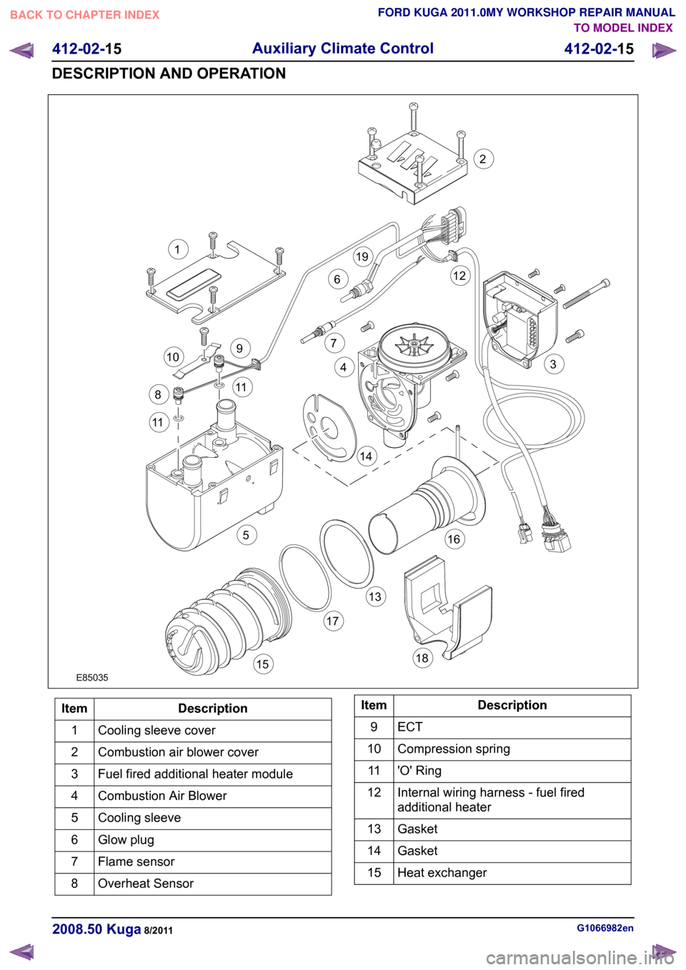
Description
Item
Cooling sleeve cover
1
Combustion air blower cover
2
Fuel fired additional heater module
3
Combustion Air Blower
4
Cooling sleeve
5
Glow plug
6
Flame sensor
7
Overheat Sensor
8 Description
Item
ECT9
Compression spring
10
'O' Ring
11
Internal wiring harness - fuel fired
additional heater
12
Gasket
13
Gasket
14
Heat exchanger
15 G1066982en
2008.50 Kuga 8/2011 412-02-15
Auxiliary Climate Control
412-02-15
DESCRIPTION AND OPERATIONTO MODEL INDEX
BACK TO CHAPTER INDEX
FORD KUGA 2011.0MY WORKSHOP REPAIR MANUALE850351132126791011115144316171518198
Page 169 of 2057

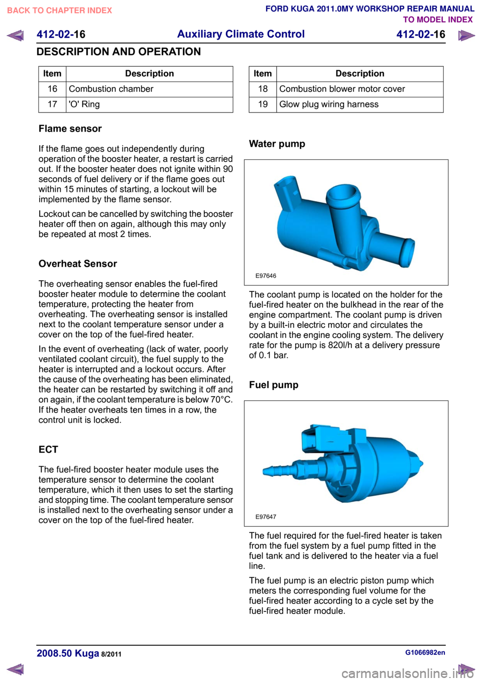
Description
Item
Combustion chamber
16
'O' Ring
17 Description
Item
Combustion blower motor cover
18
Glow plug wiring harness
19
Flame sensor
If the flame goes out independently during
operation of the booster heater, a restart is carried
out. If the booster heater does not ignite within 90
seconds of fuel delivery or if the flame goes out
within 15 minutes of starting, a lockout will be
implemented by the flame sensor.
Lockout can be cancelled by switching the booster
heater off then on again, although this may only
be repeated at most 2 times.
Overheat Sensor
The overheating sensor enables the fuel-fired
booster heater module to determine the coolant
temperature, protecting the heater from
overheating. The overheating sensor is installed
next to the coolant temperature sensor under a
cover on the top of the fuel-fired heater.
In the event of overheating (lack of water, poorly
ventilated coolant circuit), the fuel supply to the
heater is interrupted and a lockout occurs. After
the cause of the overheating has been eliminated,
the heater can be restarted by switching it off and
on again, if the coolant temperature is below 70°C.
If the heater overheats ten times in a row, the
control unit is locked.
ECT
The fuel-fired booster heater module uses the
temperature sensor to determine the coolant
temperature, which it then uses to set the starting
and stopping time. The coolant temperature sensor
is installed next to the overheating sensor under a
cover on the top of the fuel-fired heater. Water pump The coolant pump is located on the holder for the
fuel-fired heater on the bulkhead in the rear of the
engine compartment. The coolant pump is driven
by a built-in electric motor and circulates the
coolant in the engine cooling system. The delivery
rate for the pump is 820l/h at a delivery pressure
of 0.1 bar.
Fuel pump
The fuel required for the fuel-fired heater is taken
from the fuel system by a fuel pump fitted in the
fuel tank and is delivered to the heater via a fuel
line.
The fuel pump is an electric piston pump which
meters the corresponding fuel volume for the
fuel-fired heater according to a cycle set by the
fuel-fired heater module.
G1066982en
2008.50 Kuga 8/2011 412-02-16
Auxiliary Climate Control
412-02-16
DESCRIPTION AND OPERATIONTO MODEL INDEX
BACK TO CHAPTER INDEX
FORD KUGA 2011.0MY WORKSHOP REPAIR MANUALE97646 E97647
Page 183 of 2057

Instrument Cluster and Panel Illumination
Refer to
Wiring Diagrams Section 413-00, for
schematic and connector information.
Principles of Operation
NOTE: A new instrument cluster must be
configured.
The instrument cluster and panel illumination
consists of dimmable and non-dimmable
illumination. The dimmable panel illumination is
controlled by the panel illumination switch (part of
the headlamp switch), which allows the brightness
level of the backlights to be adjusted dependent
on the customer preference. When the headlamp
switch is in the parking lamps ON or headlamps
ON position, the intensity of the backlighting can
be adjusted using the panel dimmer switch. The
non dimmable illumination allows for full intensity
dependant on the ignition switch position.
Instrument Cluster and Dimmable
Backlighting A.
Tachometer
B. Engine coolant temperature gauge
C. Fuel gauge
D. Speedometer
E. Information display
The dimmable illumination utilizes light emitting
diodes (LEDs) and bulb(s). The following dimmable
components are backlight using LEDs only:
• ashtray
• cigar lighter
• transmission control lever
• heater control panel
• audio unit • navigation system display module
• instrument cluster
• climate control module
• hazard switch
• traction control system disable switch
• right-hand and left-hand heated front seat
switch(es)
Inspection and Verification
1. Verify the customer concern.
2. Visually inspect for obvious signs of mechanical
or electrical damage.
Visual Inspection Chart Electrical
Mechanical
– Fuse(s)
– Loose or corrodedconnector(s)
– Instrument cluster
– Wiring Harness
– Circuit
– LED(s)
– Bulb(s)
– Engine/engine
compartment or
underbody compon-
ents
– Fluid levels
– Accessory installa- tion
3. If an obvious cause for an observed or reported concern is found, correct the cause (if possible)
before proceeding to the next step.
4. If the cause is not visually evident, verify the symptom and refer to the diagnostic tab within
the Ford approved diagnostic tool. G1054961en
2008.50 Kuga 8/2011 413-00-2
Instrument Cluster and Panel Illumination
413-00-2
DIAGNOSIS AND TESTINGTO MODEL INDEX
BACK TO CHAPTER INDEX
FORD KUGA 2011.0MY WORKSHOP REPAIR MANUALE98738ABCED
Page 190 of 2057

Instrument Cluster
Refer to
Wiring Diagrams Section 413-01, for
schematic and connector information. General Equipment
The Ford approved diagnostic tool
Inspection and Verification
1. Verify the customer concern.
2. Visually inspect for obvious signs of mechanical
or electrical damage.
Visual Inspection Chart Electrical
Mechanical
– Fuse(s)
– Wiring harness
– Electricalconnector(s)
– Instrument cluster
– Light emitting diode(s) (LED)(s)
– Engine oil filter
– Engine oil level
–
Engine coolant level
– Oil pressure switch
– Engine coolant level
– Coolant thermostat
– Engine coolant temperature (ECT)
sensor
– Fuel gauge
– Collapsed or damaged fuel tank
– Recirculation hose
– Fuel tank filler pipe/hose
– Indicated fuel level
– Fuel lines
– Fuel tank filler cap
– Fuel filter (external to the fuel tank)
– Fuel tank
– Door adjustment
3. If an obvious cause for an observed or reported concern is found, correct the cause (if possible)
before proceeding to the next step.
4. NOTE: If none of the following warning indicators are operating correctly this may
indicate a concern with the central junction
box (CJB). If only one or two of the following
warning indicators are not operating
correctly this may indicate an instrument
cluster concern. Verify the following warning indicators are
working correctly:
• Charging.
• Turn signals.
• Headlamps.
5. If the cause is not visually evident, verify the symptom and refer to the diagnostic tab within
the Ford approved diagnostic tool.
Configuration of the Instrument Cluster
The instrument cluster is a programmable module,
which must be configured by selecting the
Programmable Module Installation Routine on the
Ford approved diagnostic tool.
NOTE: When the new instrument cluster has been
configured with the odometer value, its
configuration cannot be decreased or matched. A
new configuration will result in an increase in the
displayed odometer value by a minimum of two
units.
NOTE: The odometer value must be recorded from
the original instrument cluster before removal.
If the odometer value cannot be obtained from
the original instrument cluster (display failure)
the customer should supply the approximate
value.
The following features will need to be configured
when a new instrument cluster is installed:
• Anti-lock Brake System (ABS)
• All wheel drive
• Keyless vehicle entry
• Electronic power assisted steering
• Trip computer
• Voice control
• Parking aid
• Belt minder
• Safety belt not fastened
• Right hand drive
• Overspeed warning
• Reverse warning
• Turbocharger boost pressure
• Speed control
• Auxiliary heater
• Suspension control
• Washer fluid sensor G1054964en
2008.50 Kuga 8/2011 413-01-7
Instrument Cluster
413-01-7
DIAGNOSIS AND TESTINGTO MODEL INDEX
BACK TO CHAPTER INDEX
FORD KUGA 2011.0MY WORKSHOP REPAIR MANUAL
Page 195 of 2057

Horn
Principles of Operation
The horn system consists of a relay, a steering
wheel switch and either one or two horns. The
horn(s) receives voltage from the switched side of
the relay, and the relay switch is controlled on its
ground side by the steering wheel switch.
The horn relay, is located in the Battery junction
box (BJB) and is supplied with a permanent voltage
from the battery.
The steering wheel horn switch shares the steering
wheel clockspring circuit with the air-bag circuit.
Each of these systems work completely
independent of each other.
Inspection and Verification
1. Verify the customer concern.
2.
Visually inspect for obvious signs of mechanical
or electrical damage.
Visual Inspection Chart Electrical
• Fuse(s)
• Wiring harness
• Electrical connector(s)
• Horn switch
• Horn
• Clockspring
• Horn relay
• BJB
3. If an obvious cause for an observed or reported concern is found, correct the cause (if possible)
before proceeding to the next step.
4. If the cause is not visually evident, verify the symptom and refer to the diagnostic tab within
the Ford approved diagnostic tool. G1055042en
2008.50 Kuga 8/2011 413-06-2
Horn
413-06-2
DIAGNOSIS AND TESTINGTO MODEL INDEX
BACK TO CHAPTER INDEX
FORD KUGA 2011.0MY WORKSHOP REPAIR MANUAL
Page 197 of 2057

Warning Devices
Refer to
Wiring Diagrams Section 501-20B, for
schematic and connector information. General Equipment
Ford diagnostic equipment
Inspection and Verification
1. Verify the customer concern.
2. Visually inspect for obvious signs of mechanical
or electrical damage.
Visual Inspection Chart Electrical
Mechanical
– Wiring harness
– Electricalconnector(s)
– Safety belt buckle switch
– Restraints control module
– Safety belt buckle
3. If an obvious cause for an observed or reported concern is found, correct the cause (if possible)
before proceeding to the next step.
4. If the cause is not visually evident, verify the symptom and refer to the Ford diagnostic
equipment to diagnose the system. G1055053en
2008.50 Kuga 8/2011 413-09-2
Warning Devices
413-09-2
DIAGNOSIS AND TESTINGTO MODEL INDEX
BACK TO CHAPTER INDEX
FORD KUGA 2011.0MY WORKSHOP REPAIR MANUAL
Page 212 of 2057

Parking Aid Camera
For vehicles with a DVD navigation system with a
touch screen, the parking aid camera is supplied
as standard. For vehicles with a standard
navigation system, the camera can be ordered as
an optional extra. The system essentially consists
of a camera with a wide angle lens, a control unit
and a wiring harness which is not integrated in the
vehicle wiring harness.
On the navigation display screen, the drivers sees
a video image of the area behind the vehicle.
Guides integrated in the camera images by the
parking aid camera module and displayed on the
screen help the driver to find out about the steering
angle, vehicle width, cornering and driving straight
ahead. The system generates these guides using:
• Vehicle parameters (length, width)
• Steering Angle
• Vehicle position during the parking maneuverDescription
Item
Monitoring angle
1
If the vehicle is also fitted with a rear parking aid,
the distances to the obstacle are displayed as a
3D illustration. G1034399en
2008.50 Kuga 8/2011 413-13-13
Parking Aid
413-13-13
DESCRIPTION AND OPERATIONTO MODEL INDEX
BACK TO CHAPTER INDEX
FORD KUGA 2011.0MY WORKSHOP REPAIR MANUAL0,3m120,11E97904 E97905