2011 FORD KUGA oil
[x] Cancel search: oilPage 1790 of 2057
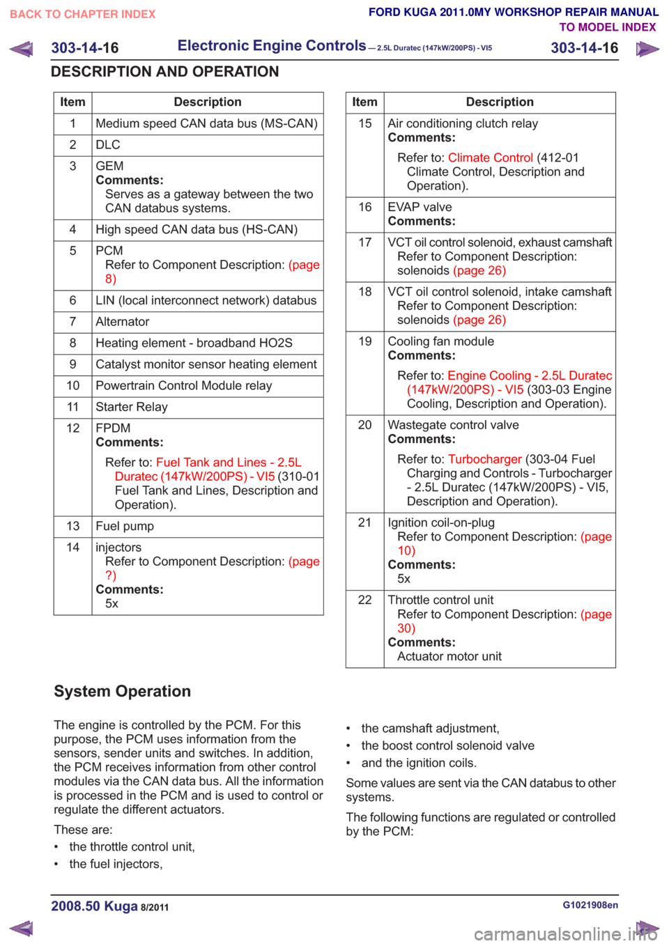
Description
Item
Medium speed CAN data bus (MS-CAN)
1
DLC
2
GEM
Comments:Serves as a gateway between the two
CAN databus systems.
3
High speed CAN data bus (HS-CAN)
4
PCMRefertoComponentDescription:(page
8)
5
LIN (local interconnect network) databus
6
Alternator
7
Heating element - broadband HO2S
8
Catalyst monitor sensor heating element
9
Powertrain Control Module relay
10
Starter Relay
11
FPDM
Comments:Refer to: Fuel Tank and Lines - 2.5L
Duratec (147kW/200PS) - VI5 (310-01
Fuel Tank and Lines, Description and
Operation).
12
Fuel pump
13
injectorsRefertoComponentDescription:(page
?)
Comments: 5x
14Description
Item
Air conditioning clutch relay
Comments:Refer to: Climate Control (412-01
Climate Control, Description and
Operation).
15
EVAP valve
Comments:
16
VCT oil control solenoid, exhaust camshaftRefer to Component Description:
solenoids(page26)
17
VCT oil control solenoid, intake camshaftRefer to Component Description:
solenoids(page26)
18
Cooling fan module
Comments:Refer to: Engine Cooling - 2.5L Duratec
(147kW/200PS) - VI5 (303-03 Engine
Cooling, Description and Operation).
19
Wastegate control valve
Comments:Refer to: Turbocharger (303-04 Fuel
Charging and Controls - Turbocharger
- 2.5L Duratec (147kW/200PS) - VI5,
Description and Operation).
20
Ignition coil-on-plugRefertoComponentDescription:(page
10)
Comments: 5x
21
Throttle control unitRefertoComponentDescription:(page
30)
Comments: Actuator motor unit
22
System Operation
The engine is controlled by the PCM. For this
purpose, the PCM uses information from the
sensors, sender units and switches. In addition,
the PCM receives information from other control
modules via the CAN data bus. All the information
is processed in the PCM and is used to control or
regulate the different actuators.
These are:
• the throttle control unit,
• the fuel injectors, • the camshaft adjustment,
• the boost control solenoid valve
• and the ignition coils.
Some values are sent via the CAN databus to other
systems.
The following functions are regulated or controlled
by the PCM:
G1021908en2008.50 Kuga8/2011
303-14-
16
Electronic Engine Controls— 2.5L Duratec (147kW/200PS) - VI5303-14-
16
DESCRIPTION AND OPERATION
TO MODEL INDEX
BACK TO CHAPTER INDEX
FORD KUGA 2011.0MY WORKSHOP REPAIR MANUAL
Page 1791 of 2057
• Starting process
• Engine running– Fuel supply to the engine including lambdacontrol
– Ignition setting including knock control
– Idle speed control
– Boost pressure control
– Valve timing via the camshaft adjuster for the intake and exhaust camshafts (including
internal exhaust gas recirculation)
• Refrigerant compressor (activation, deactivation and delivery)
• EVAP purge valve
• Charging system
Fuel is supplied to the engine via a sequential
multi-point injection system. Ignition is performed
by a distributor-less ignition system with one
ignition coil unit for each cylinder.
The PCM optimizes engine power and emissions
at all times by processing the sensor signals and
information received via the CAN databus and
using these for open or closed loop control of the
different variables.
The PCM contains part of the PATS (passive
anti-theft system).
The PCM is supplied with battery voltage via a fuse
in the BJB (battery junction box). This power supply
is needed to ensure that saved data is not lost
when the engine is switched off.
For other power supply requirements, the PCM
switches on a relay in the BJB which is responsible
for supplying power to the PCM and to some
sensors and actuators. Each of these are protected
by fuses in the BJB.
To guarantee optimum engine running at all times,
the PCM has several adaptive (self-learning)
functions. These adapt the output signals to
changing circumstances, such as wear or system
faults.
In some cases a faulty signal is replaced with a
substitute value or limited. A substitute value can
be calculated from other signals or it can be
predefined by the PCM. The substitute value allows
the vehicle to keep on running without the emission
values changing unduly. Depending on the signal
failure, the PCM operates in emergency mode. In
this mode, the engine power and/or the engine
speed is reduced to prevent further damage.
Depending on the faulty signal, a fault code is
stored in the error memory of the PCM. These can be read out using IDS (Integrated Diagnostic
System) via the DLC.
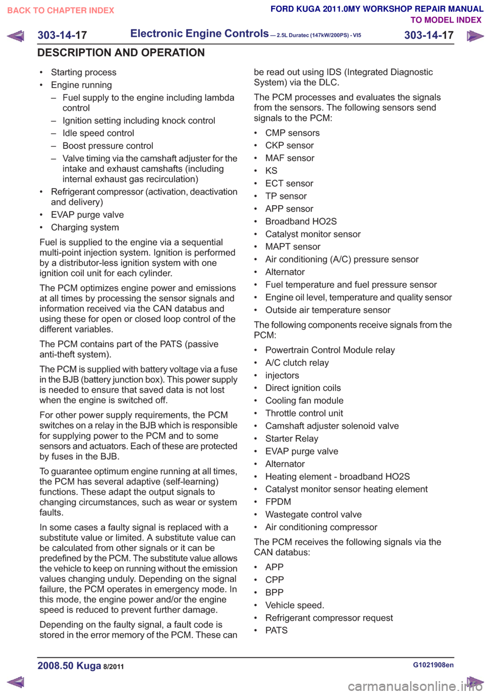
The PCM processes and evaluates the signals
from the sensors. The following sensors send
signals to the PCM:
• CMP sensors
• CKP sensor
• MAF sensor
•KS
• ECT sensor
• TP sensor
• APP sensor
• Broadband HO2S
• Catalyst monitor sensor
• MAPT sensor
• Air conditioning (A/C) pressure sensor
• Alternator
• Fuel temperature and fuel pressure sensor
• Engine oil level, temperature and quality sensor
• Outside air temperature sensor
The following components receive signals from the
PCM:
• Powertrain Control Module relay
• A/C clutch relay
• injectors
• Direct ignition coils
• Cooling fan module
• Throttle control unit
• Camshaft adjuster solenoid valve
• Starter Relay
• EVAP purge valve
• Alternator
• Heating element - broadband HO2S
• Catalyst monitor sensor heating element
• FPDM
• Wastegate control valve
• Air conditioning compressor
The PCM receives the following signals via the
CAN databus:
• APP
•CPP
• BPP
• Vehicle speed.
• Refrigerant compressor request
• PAT S
G1021908en2008.50 Kuga8/2011
303-14-
17
Electronic Engine Controls— 2.5L Duratec (147kW/200PS) - VI5303-14-
17
DESCRIPTION AND OPERATION
TO MODEL INDEX
BACK TO CHAPTER INDEX
FORD KUGA 2011.0MY WORKSHOP REPAIR MANUAL
Page 1796 of 2057
current value is reached. The PCM then
permanently connects the heating element to earth.
The catalyst monitor sensor is used by the PCM
to measure the oxygen content in the exhaust gas
in the TWC. If all the conditions for catalyst
diagnostics are met, based on this information the
PCM can check that the TWC is working
satisfactorily. The information is also used to
improve the air/fuel mixture adjustment.
The catalyst monitor sensor is similar in function
to an HO2S. The signal transmitted by the catalyst
monitor sensor changes sharply if the oxygen
content in the exhaust gas changes. For this
reason, catalyst monitor sensors are also called
"jump lambda sensors".
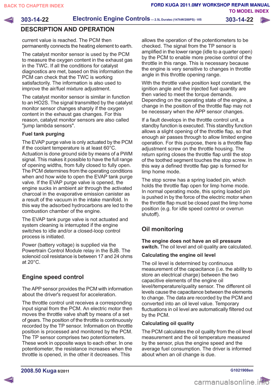
Fuel tank purging
The EVAP purge valve is only actuated by the PCM
if the coolant temperature is at least 60°C.
Actuation is done ground side by means of a PWM
signal. This makes it possible to have the full range
of opening widths, from fully closed to fully open.
The PCM determines from the operating conditions
when and how wide to open the EVAP tank purge
valve. If the EVAP purge valve is opened, the
engine sucks in ambient air through the activated
charcoal in the evaporative emission canister as
a result of the vacuum in the intake manifold. In
this way the adsorbed hydrocarbons are led to the
combustion chamber of the engine.
The EVAP tank purge valve is not actuated and
system cleaning is interrupted if the engine
switches to idle and/or a closed-loop control
process is initiated.
Power (battery voltage) is supplied via the
Powertrain Control Module relay in the BJB. The
solenoid coil resistance is between 17 and 24 ohms
at 20°C.
Engine speed control
The APP sensor provides the PCM with information
about the driver's request for acceleration.
The throttle control unit receives a corresponding
input signal from the PCM. An electric motor then
moves the throttle valve shaft by means of a set
of gears. The position of the throttle is continuously
recorded by the TP sensor. Information on throttle
position is processed and monitored by the PCM.
The TP sensor comprises two potentiometers.
These work in opposite ways to each other. In one
potentiometer, the resistance increases when the
throttle is opened, in the other it decreases. Thisallows the operation of the potentiometers to be
checked. The signal from the TP sensor is
amplified in the lower range (idle to a quarter open)
by the PCM to enable more precise control of the
throttle in this range. This is necessary because
the engine is very sensitive to changes in throttle
angle in this throttle opening range.
With the throttle valve position kept constant, the
ignition angle and the injected fuel quantity are
then varied to meet the torque demands.
Depending on the operating state of the engine, a
change in the position of the throttle flap may not
be necessary when the APP sensor changes.
If a fault develops in the throttle control unit, a
standby function is executed. This standby function
allows a slight opening of the throttle flap, so that
enough air passes through to allow limited engine
operation. For this purpose, there is a throttle flap
adjustment screw on the throttle housing. The
return spring closes the throttle flap until the stop
of the toothed segment touches the stop screw. In
this way a defined throttle flap gap is formed for
limp home mode.
The stop screw has a spring loaded pin, which
holds the throttle flap open for limp home mode.
In normal operating mode, this spring loaded pin
is pushed in by the force of the electric motor when
the throttle flap must be closed past the limp home
position (e.g. for idle speed control or overrun
shutoff).
Oil monitoring
The engine does not have an oil pressure
switch.
The oil level and oil quality are calculated.
Calculating the engine oil level
The oil level is determined by continuous
measurement of the capacitance (i.e. the ability to
store an electrical charge) between the two
capacitive elements of the engine oil
level/temperature/quality sensor. The different oil
levels cause the capacitance between the elements
to change. The data are recorded by the PCM and
converted into an oil level value. Temporary
fluctuations in oil level are automatically filtered out
by the PCM.
Calculating oil quality
The PCM calculates the oil quality from the oil level
measurement and the oil temperature measured
by the sensor, plus the engine speed and the
average fuel consumption. The driver is informed
about when an oil change is due.
G1021908en2008.50 Kuga8/2011
303-14- 22
Electronic Engine Controls— 2.5L Duratec (147kW/200PS) - VI5303-14-
22
DESCRIPTION AND OPERATION
TO MODEL INDEX
BACK TO CHAPTER INDEX
FORD KUGA 2011.0MY WORKSHOP REPAIR MANUAL
Page 1797 of 2057
Calculation of valve timing adjustment
angle
The 2.5L Duratec (VI5) engine has two camshaft
adjustment units which work independently of each
other.
One camshaft adjustment solenoid is installed for
each intake camshaft and exhaust camshaft.
This allows the PCM to continuously adjust the
intake and exhaust-side camshaft adjustments
independently of one another. The timing is
adjusted by the PCM using curves; adjustment is
primarily done as a function of engine load and
engine speed.
In this way the engine performance is increased
and internal exhaust gas recirculation is realized.
The advantages of camshaft adjustment are as
follows:
• Higher torque and improved torquecharacteristics
• Reduced fuel consumption
• Improved emissions performance
The camshaft adjustment solenoids are actuated
by the PWM by means of a PCM signal.
Continuous adjustment of the camshafts by the
PCM is achieved by means of the camshaft
adjustment solenoids, the camshaft adjustment
units and two CMP sensors. A defined quantity of
engine is oil is supplied to or drained from the
adjustment units via the camshaft adjustment
solenoids. The existing EOP (engine oil pressure)
is taken into account in the process. In this way
the valve timings are adjusted according to the
operating condition of the engine. The camshaft
adjusters work according to the vane-cell principle.
On starting the engine, both camshafts are
mechanically locked in their starting positions. The
intake camshaft is in the maximum late position
and the exhaust camshaft in the maximum early
position.
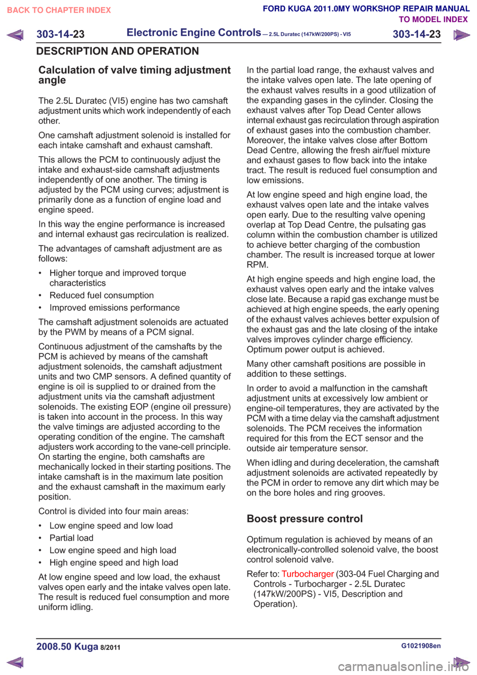
Control is divided into four main areas:
• Low engine speed and low load
• Partial load
• Low engine speed and high load
• High engine speed and high load
At low engine speed and low load, the exhaust
valves open early and the intake valves open late.
The result is reduced fuel consumption and more
uniform idling. In the partial load range, the exhaust valves and
the intake valves open late. The late opening of
the exhaust valves results in a good utilization of
the expanding gases in the cylinder. Closing the
exhaust valves after Top Dead Center allows
internal exhaust gas recirculation through aspiration
of exhaust gases into the combustion chamber.
Moreover, the intake valves close after Bottom
Dead Centre, allowing the fresh air/fuel mixture
and exhaust gases to flow back into the intake
tract. The result is reduced fuel consumption and
low emissions.
At low engine speed and high engine load, the
exhaust valves open late and the intake valves
open early. Due to the resulting valve opening
overlap at Top Dead Centre, the pulsating gas
column within the combustion chamber is utilized
to achieve better charging of the combustion
chamber. The result is increased torque at lower
RPM.
At high engine speeds and high engine load, the
exhaust valves open early and the intake valves
close late. Because a rapid gas exchange must be
achieved at high engine speeds, the early opening
of the exhaust valves achieves better expulsion of
the exhaust gas and the late closing of the intake
valves improves cylinder charge efficiency.
Optimum power output is achieved.
Many other camshaft positions are possible in
addition to these settings.
In order to avoid a malfunction in the camshaft
adjustment units at excessively low ambient or
engine-oil temperatures, they are activated by the
PCM with a time delay via the camshaft adjustment
solenoids. The PCM receives the information
required for this from the ECT sensor and the
outside air temperature sensor.
When idling and during deceleration, the camshaft
adjustment solenoids are activated repeatedly by
the PCM in order to remove any dirt which may be
on the bore holes and ring grooves.
Boost pressure control
Optimum regulation is achieved by means of an
electronically-controlled solenoid valve, the boost
control solenoid valve.
Refer to:
Turbocharger (303-04 Fuel Charging and
Controls - Turbocharger - 2.5L Duratec
(147kW/200PS) - VI5, Description and
Operation).
G1021908en2008.50 Kuga8/2011
303-14- 23
Electronic Engine Controls— 2.5L Duratec (147kW/200PS) - VI5303-14-
23
DESCRIPTION AND OPERATION
TO MODEL INDEX
BACK TO CHAPTER INDEX
FORD KUGA 2011.0MY WORKSHOP REPAIR MANUAL
Page 1798 of 2057
Starting process
The PCM enables the starting process when a key
providing a valid code is read via the PATS.
Refer to:Starting System (303-06 Starting System
- 2.5L Duratec (147kW/200PS) - VI5, Description
and Operation).
Alternator control (Smart Charge)
The vehicle is fitted with a Smart Charging charge
system.
In this system, the charge voltage is regulated by
the PCM.
Refer to: Generator (414-02 Generator and
Regulator, Description and Operation).
Component Description
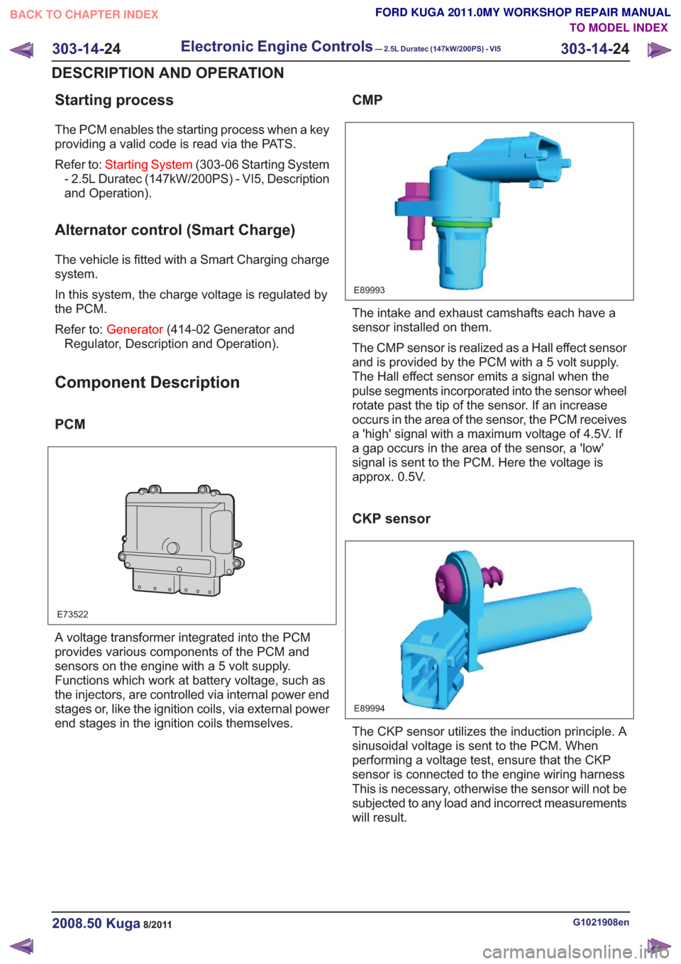
PCM
E73522
A voltage transformer integrated into the PCM
provides various components of the PCM and
sensors on the engine with a 5 volt supply.
Functions which work at battery voltage, such as
the injectors, are controlled via internal power end
stages or, like the ignition coils, via external power
end stages in the ignition coils themselves.
CMP
E89993
The intake and exhaust camshafts each have a
sensor installed on them.
The CMP sensor is realized as a Hall effect sensor
and is provided by the PCM with a 5 volt supply.
The Hall effect sensor emits a signal when the
pulse segments incorporated into the sensor wheel
rotate past the tip of the sensor. If an increase
occurs in the area of the sensor, the PCM receives
a 'high' signal with a maximum voltage of 4.5V. If
a gap occurs in the area of the sensor, a 'low'
signal is sent to the PCM. Here the voltage is
approx. 0.5V.
CKP sensor
E89994
The CKP sensor utilizes the induction principle. A
sinusoidal voltage is sent to the PCM. When
performing a voltage test, ensure that the CKP
sensor is connected to the engine wiring harness
This is necessary, otherwise the sensor will not be
subjected to any load and incorrect measurements
will result.
G1021908en2008.50 Kuga8/2011
303-14- 24
Electronic Engine Controls— 2.5L Duratec (147kW/200PS) - VI5303-14-
24
DESCRIPTION AND OPERATION
TO MODEL INDEX
BACK TO CHAPTER INDEX
FORD KUGA 2011.0MY WORKSHOP REPAIR MANUAL
Page 1801 of 2057
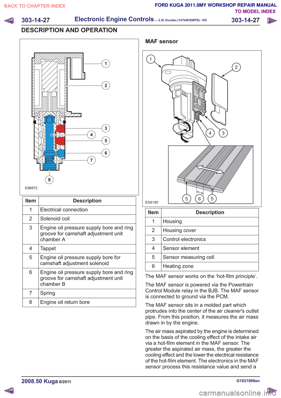
E96872
1
2
3
5
4
6
7
8
Description
Item
Electrical connection
1
Solenoid coil
2
Engine oil pressure supply bore and ring
groove for camshaft adjustment unit
chamber A
3
Tappet
4
Engine oil pressure supply bore for
camshaft adjustment solenoid
5
Engine oil pressure supply bore and ring
groove for camshaft adjustment unit
chamber B
6
Spring
7
Engine oil return bore
8
MAF sensor
E58185
1
2
43
565
Description
Item
Housing
1
Housing cover
2
Control electronics
3
Sensor element
4
Sensor measuring cell
5
Heating zone
6
The MAF sensor works on the ‘hot-film principle’.
The MAF sensor is powered via the Powertrain
Control Module relay in the BJB. The MAF sensor
is connected to ground via the PCM.
The MAF sensor sits in a molded part which
protrudes into the center of the air cleaner's outlet
pipe. From this position, it measures the air mass
drawn in by the engine.
The air mass aspirated by the engine is determined
on the basis of the cooling effect of the intake air
via a hot-film element in the MAF sensor. The
greater the aspirated air mass, the greater the
cooling effect and the lower the electrical resistance
of the hot-film element. The electronics in the MAF
sensor process this resistance value and send a
G1021908en2008.50 Kuga8/2011
303-14- 27
Electronic Engine Controls— 2.5L Duratec (147kW/200PS) - VI5303-14-
27
DESCRIPTION AND OPERATION
TO MODEL INDEX
BACK TO CHAPTER INDEX
FORD KUGA 2011.0MY WORKSHOP REPAIR MANUAL
Page 1803 of 2057
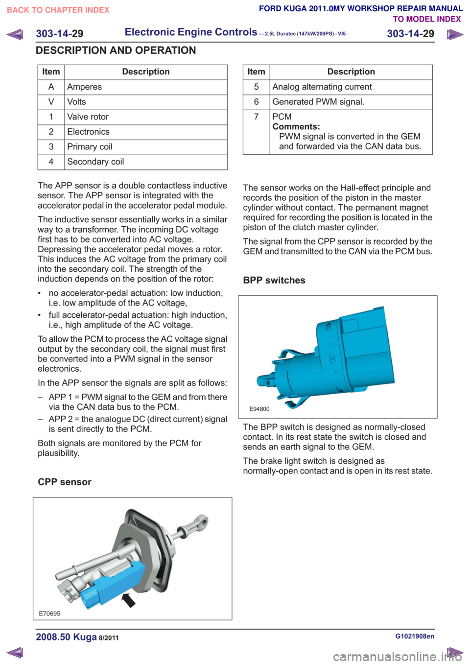
Description
Item
Amperes
A
Volts
V
Valve rotor
1
Electronics
2
Primary coil
3
Secondary coil
4Description
Item
Analog alternating current
5
Generated PWM signal.
6
PCM
Comments:PWM signal is converted in the GEM
and forwarded via the CAN data bus.
7
The APP sensor is a double contactless inductive
sensor. The APP sensor is integrated with the
accelerator pedal in the accelerator pedal module.
The inductive sensor essentially works in a similar
way to a transformer. The incoming DC voltage
first has to be converted into AC voltage.
Depressing the accelerator pedal moves a rotor.
This induces the AC voltage from the primary coil
into the secondary coil. The strength of the
induction depends on the position of the rotor:
• no accelerator-pedal actuation: low induction, i.e. low amplitude of the AC voltage,
• full accelerator-pedal actuation: high induction, i.e., high amplitude of the AC voltage.
To allow the PCM to process the AC voltage signal
output by the secondary coil, the signal must first
be converted into a PWM signal in the sensor
electronics.
In the APP sensor the signals are split as follows:
– APP 1 = PWM signal to the GEM and from there via the CAN data bus to the PCM.
– APP 2 = the analogue DC (direct current) signal is sent directly to the PCM.
Both signals are monitored by the PCM for
plausibility.
CPP sensor
E70695
The sensor works on the Hall-effect principle and
records the position of the piston in the master
cylinder without contact. The permanent magnet
required for recording the position is located in the
piston of the clutch master cylinder.
The signal from the CPP sensor is recorded by the
GEM and transmitted to the CAN via the PCM bus.
BPP switches
E94800
The BPP switch is designed as normally-closed
contact. In its rest state the switch is closed and
sends an earth signal to the GEM.
The brake light switch is designed as
normally-open contact and is open in its rest state.
G1021908en2008.50 Kuga8/2011
303-14- 29
Electronic Engine Controls— 2.5L Duratec (147kW/200PS) - VI5303-14-
29
DESCRIPTION AND OPERATION
TO MODEL INDEX
BACK TO CHAPTER INDEX
FORD KUGA 2011.0MY WORKSHOP REPAIR MANUAL
Page 1806 of 2057
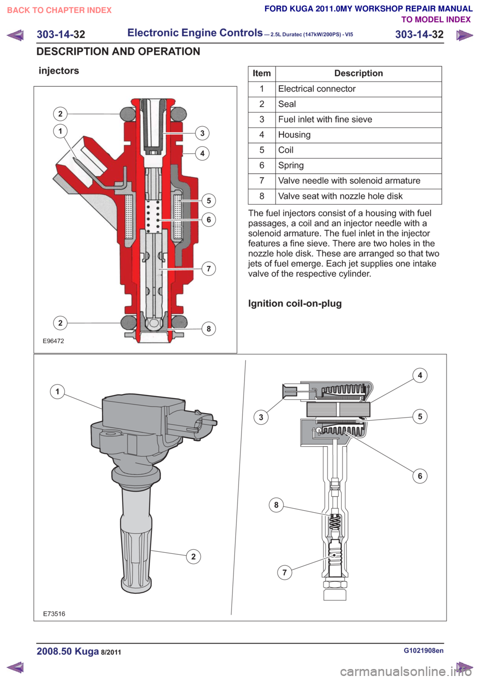
injectors
E96472
2
3
4
5
6
7
8
1
2
Description
Item
Electrical connector
1
Seal
2
Fuel inlet with fine sieve
3
Housing
4
Coil
5
Spring
6
Valve needle with solenoid armature
7
Valve seat with nozzle hole disk
8
The fuel injectors consist of a housing with fuel
passages, a coil and an injector needle with a
solenoid armature. The fuel inlet in the injector
features a fine sieve. There are two holes in the
nozzle hole disk. These are arranged so that two
jets of fuel emerge. Each jet supplies one intake
valve of the respective cylinder.
Ignition coil-on-plug
E73516
2
1
3
4
5
6
7
8
G1021908en2008.50 Kuga8/2011
303-14- 32
Electronic Engine Controls— 2.5L Duratec (147kW/200PS) - VI5303-14-
32
DESCRIPTION AND OPERATION
TO MODEL INDEX
BACK TO CHAPTER INDEX
FORD KUGA 2011.0MY WORKSHOP REPAIR MANUAL