2011 FORD KUGA air condition
[x] Cancel search: air conditionPage 1237 of 2057
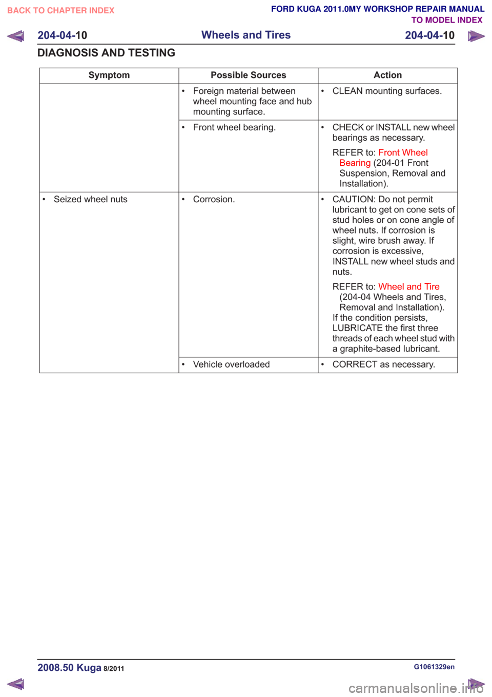
Action
Possible Sources
Symptom
• CLEAN mounting surfaces.
• Foreign material between
wheel mounting face and hub
mounting surface.
• CHECK or INSTALL new wheelbearings as necessary.
REFER to: Front Wheel
Bearing (204-01 Front
Suspension, Removal and
Installation).
• Front wheel bearing.
• CAUTION: Do not permitlubricant to get on cone sets of
stud holes or on cone angle of
wheel nuts. If corrosion is
slight, wire brush away. If
corrosion is excessive,
INSTALL new wheel studs and
nuts.
REFER to: Wheel and Tire
(204-04 Wheels and Tires,
Removal and Installation).
If the condition persists,
LUBRICATE the first three
threads of each wheel stud with
a graphite-based lubricant.
• Corrosion.
• Seized wheel nuts
• CORRECT as necessary.
• Vehicle overloaded
G1061329en2008.50 Kuga8/2011
204-04- 10
Wheels and Tires
204-04- 10
DIAGNOSIS AND TESTING
TO MODEL INDEX
BACK TO CHAPTER INDEX
FORD KUGA 2011.0MY WORKSHOP REPAIR MANUAL
Page 1251 of 2057
Rear Drive Axle and Differential – System Operation andComponent Description
System Operation
General Information
The powertrain with all-wheel drive consists of the
following main components:
• engine
• transaxle with front axle differential
• transfer box
• halfshafts and driveshafts
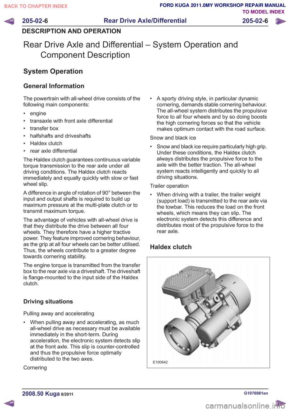
• Haldex clutch
• rear axle differential
The Haldex clutch guarantees continuous variable
torque transmission to the rear axle under all
driving conditions. The Haldex clutch reacts
immediately and equally quickly with slow or fast
wheel slip.
A difference in angle of rotation of 90° between the
input and output shafts is required to build up
maximum pressure at the multi-plate clutch or to
transmit maximum torque.
The advantage of vehicles with all-wheel drive is
that they distribute the drive between all four
wheels. They therefore have a higher tractive
power. They feature improved cornering behaviour,
as the grip at all four wheels can be better utilised.
Thus, the wheels contribute to a greater degree
towards cornering stability.
The engine torque is transmitted from the transfer
box to the rear axle via a driveshaft. The driveshaft
is flange-mounted to the input side of the Haldex
clutch.
Driving situations
Pulling away and accelerating
• When pulling away and accelerating, as muchall-wheel drive as necessary must be available
immediately in the short-term. During
acceleration, the electronic system detects slip
at the front axle. This slip is counter-controlled
and thus the propulsive force optimally
distributed to the two axes.
Cornering • A sporty driving style, in particular dynamic
cornering, demands stable cornering behaviour.
The all-wheel system distributes the propulsive
force to all four wheels and by so doing boosts
the high cornering forces so that the vehicle
makes optimum contact with the road surface.
Snow and black ice
• Snow and black ice require particularly high grip. Under these conditions, the Haldex clutch
always distributes the propulsive force to the
axle with the better traction. The all-wheel
system reacts intelligently and quickly to all
driving situations.
Trailer operation
• When driving with a trailer, the trailer weight (support load) is transmitted to the rear axle via
the towbar. This reduces the load on the front
wheels, which means they can slip. The
electronic system detects this difference and
distributes most of the propulsive force to the
rear axle.
Haldex clutch
E100642
G1076981en2008.50 Kuga8/2011
205-02- 6
Rear Drive Axle/Differential
205-02- 6
DESCRIPTION AND OPERATION
TO MODEL INDEX
BACK TO CHAPTER INDEX
FORD KUGA 2011.0MY WORKSHOP REPAIR MANUAL
Page 1261 of 2057
6
7
8
9
10
11
1
2
3
4
5
6
7
8
9
10
11
E114914
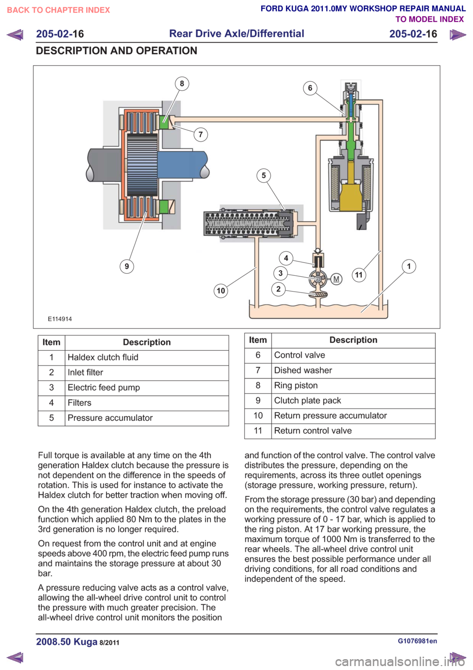
Description
Item
Haldex clutch fluid
1
Inlet filter
2
Electric feed pump
3
Filters4
Pressure accumulator
5Description
Item
Control valve
6
Dished washer
7
Ring piston
8
Clutch plate pack
9
Return pressure accumulator
10
Return control valve
11
Full torque is available at any time on the 4th
generation Haldex clutch because the pressure is
not dependent on the difference in the speeds of
rotation. This is used for instance to activate the
Haldex clutch for better traction when moving off.
On the 4th generation Haldex clutch, the preload
function which applied 80 Nm to the plates in the
3rd generation is no longer required.
On request from the control unit and at engine
speeds above 400 rpm, the electric feed pump runs
and maintains the storage pressure at about 30
bar.
A pressure reducing valve acts as a control valve,
allowing the all-wheel drive control unit to control
the pressure with much greater precision. The
all-wheel drive control unit monitors the position and function of the control valve. The control valve
distributes the pressure, depending on the
requirements, across its three outlet openings
(storage pressure, working pressure, return).
From the storage pressure (30 bar) and depending
on the requirements, the control valve regulates a
working pressure of 0 - 17 bar, which is applied to
the ring piston. At 17 bar working pressure, the
maximum torque of 1000 Nm is transferred to the
rear wheels. The all-wheel drive control unit
ensures the best possible performance under all
driving conditions, for all road conditions and
independent of the speed.
G1076981en2008.50 Kuga8/2011
205-02-
16
Rear Drive Axle/Differential
205-02- 16
DESCRIPTION AND OPERATION
TO MODEL INDEX
BACK TO CHAPTER INDEX
FORD KUGA 2011.0MY WORKSHOP REPAIR MANUAL
Page 1298 of 2057
Front Drive Halfshafts
Inspection and Verification
NOTE:New front wheel drive halfshafts should not
be installed unless disassembly and inspection
reveals unusual wear.
1. Inspect front wheel driveshaft joint boots for evidence of cracks, tears or splits.
NOTE: While inspecting the front wheel driveshaft
CV joint boots, watch for indentations (dimples) in
the boot convolutions. If an indentation is observed,
it must be removed.
2. Inspect the underbody for any indication of grease splatter in the vicinity of the front wheel
driveshaft CV joint boots outboard and inboard
locations, which is an indication of front wheel
driveshaft CV joint boot and/or front wheel
driveshaft CV joint boot clamp damage. 3. Inspect for inboard CV joint stub shaft pilot
bearing housing seal leakage at the front wheel
driveshaft CV joint.
4. Make sure front axle wheel hub retainer is the correct prevailing torque type.
5. The silicone front wheel driveshaft CV joint boot will sweat during operation, causing a light film
of grease to show on the outside of the front
wheel driveshaft CV joint boot. This condition
is normal.
NOTE: Halfshafts are not balanced and do not
contribute to rotational vibration.
6. If the concerns remain after the inspection, determine the symptoms and go to the Symptom
Chart. For additional Noise, Vibration and
Harshness (NVH). REFER to Section 100-04
[Noise, Vibration and Harshness] .
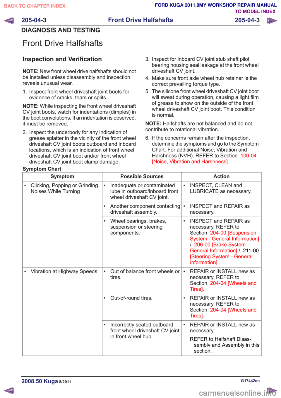
Symptom Chart
Action
Possible Sources
Symptom
• INSPECT, CLEAN andLUBRICATE as necessary.
• Inadequate or contaminated
lube in outboard/inboard front
wheel driveshaft CV joint.
• Clicking, Popping or Grinding
Noises While Turning
• INSPECT and REPAIR asnecessary.
• Another component contacting
driveshaft assembly.
• INSPECT and REPAIR asnecessary. REFER to
Section 204-00 [Suspension
System - General Information]
/ 206-00 [Brake System -
General Information] /211-00
[Steering System - General
Information] .
• Wheel bearings, brakes,
suspension or steering
components.
• REPAIR or INSTALL new asnecessary. REFER to
Section 204-04 [Wheels and
Tires] .
• Out of balance front wheels or
tires.
• Vibration at Highway Speeds
• REPAIR or INSTALL new asnecessary. REFER to
Section 204-04 [Wheels and
Tires] .
• Out-of-round tires.
• REPAIR or INSTALL new asnecessary.
REFER to Halfshaft Disas-
semblv and Assembly in this
section.
• Incorrectly seated outboard
front wheel driveshaft CV joint
in front wheel hub.
G17442en2008.50 Kuga8/2011
205-04- 3
Front Drive Halfshafts
205-04- 3
DIAGNOSIS AND TESTING
TO MODEL INDEX
BACK TO CHAPTER INDEX
FORD KUGA 2011.0MY WORKSHOP REPAIR MANUAL
Page 1340 of 2057
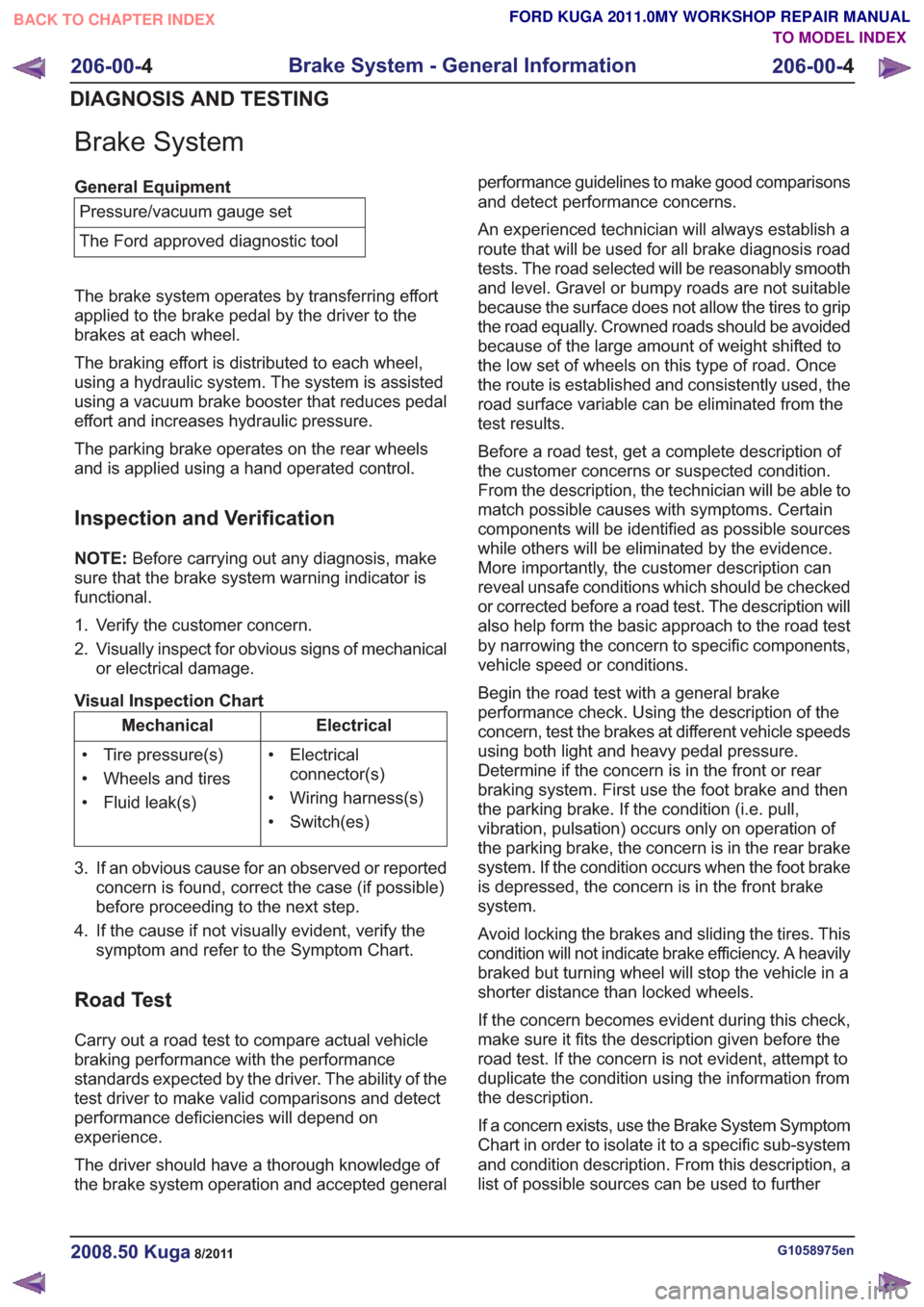
Brake System
General EquipmentPressure/vacuum gauge set
The Ford approved diagnostic tool
The brake system operates by transferring effort
applied to the brake pedal by the driver to the
brakes at each wheel.
The braking effort is distributed to each wheel,
using a hydraulic system. The system is assisted
using a vacuum brake booster that reduces pedal
effort and increases hydraulic pressure.
The parking brake operates on the rear wheels
and is applied using a hand operated control.
Inspection and Verification
NOTE: Before carrying out any diagnosis, make
sure that the brake system warning indicator is
functional.
1. Verify the customer concern.
2. Visually inspect for obvious signs of mechanical or electrical damage.
Visual Inspection Chart
Electrical
Mechanical
• Electricalconnector(s)
• Wiring harness(s)
• Switch(es)
• Tire pressure(s)
• Wheels and tires
• Fluid leak(s)
3. If an obvious cause for an observed or reported concern is found, correct the case (if possible)
before proceeding to the next step.
4. If the cause if not visually evident, verify the symptom and refer to the Symptom Chart.
Road Test
Carry out a road test to compare actual vehicle
braking performance with the performance
standards expected by the driver. The ability of the
test driver to make valid comparisons and detect
performance deficiencies will depend on
experience.
The driver should have a thorough knowledge of
the brake system operation and accepted general performance guidelines to make good comparisons
and detect performance concerns.
An experienced technician will always establish a
route that will be used for all brake diagnosis road
tests. The road selected will be reasonably smooth
and level. Gravel or bumpy roads are not suitable
because the surface does not allow the tires to grip
the road equally. Crowned roads should be avoided
because of the large amount of weight shifted to
the low set of wheels on this type of road. Once
the route is established and consistently used, the
road surface variable can be eliminated from the
test results.
Before a road test, get a complete description of
the customer concerns or suspected condition.
From the description, the technician will be able to
match possible causes with symptoms. Certain
components will be identified as possible sources
while others will be eliminated by the evidence.
More importantly, the customer description can
reveal unsafe conditions which should be checked
or corrected before a road test. The description will
also help form the basic approach to the road test
by narrowing the concern to specific components,
vehicle speed or conditions.
Begin the road test with a general brake
performance check. Using the description of the
concern, test the brakes at different vehicle speeds
using both light and heavy pedal pressure.
Determine if the concern is in the front or rear
braking system. First use the foot brake and then
the parking brake. If the condition (i.e. pull,
vibration, pulsation) occurs only on operation of
the parking brake, the concern is in the rear brake
system. If the condition occurs when the foot brake
is depressed, the concern is in the front brake
system.
Avoid locking the brakes and sliding the tires. This
condition will not indicate brake efficiency. A heavily
braked but turning wheel will stop the vehicle in a
shorter distance than locked wheels.
If the concern becomes evident during this check,
make sure it fits the description given before the
road test. If the concern is not evident, attempt to
duplicate the condition using the information from
the description.
If a concern exists, use the Brake System Symptom
Chart in order to isolate it to a specific sub-system
and condition description. From this description, a
list of possible sources can be used to further
G1058975en2008.50 Kuga8/2011
206-00-
4
Brake System - General Information
206-00- 4
DIAGNOSIS AND TESTING
TO MODEL INDEX
BACK TO CHAPTER INDEX
FORD KUGA 2011.0MY WORKSHOP REPAIR MANUAL
Page 1341 of 2057
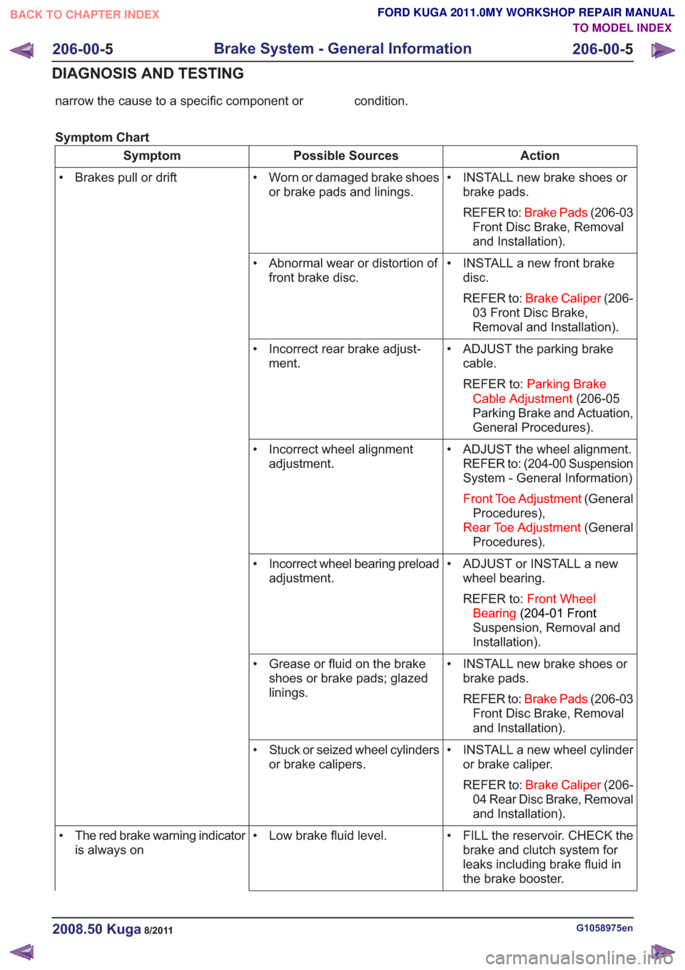
narrow the cause to a specific component or condition.
Symptom Chart
Action
Possible Sources
Symptom
• INSTALL new brake shoes orbrake pads.
REFER to: Brake Pads (206-03
Front Disc Brake, Removal
and Installation).
• Worn or damaged brake shoes
or brake pads and linings.
• Brakes pull or drift
• INSTALL a new front brakedisc.
REFER to: Brake Caliper (206-
03 Front Disc Brake,
Removal and Installation).
• Abnormal wear or distortion of
front brake disc.
• ADJUST the parking brakecable.
REFER to: Parking Brake
Cable Adjustment (206-05
Parking Brake and Actuation,
General Procedures).
• Incorrect rear brake adjust-
ment.
• ADJUST the wheel alignment.REFER to: (204-00 Suspension
System - General Information)
Front Toe Adjustment (General
Procedures),
Rear Toe Adjustment (General
Procedures).
• Incorrect wheel alignment
adjustment.
• ADJUST or INSTALL a newwheel bearing.
REFER to: Front Wheel
Bearing (204-01 Front
Suspension, Removal and
Installation).
• Incorrect wheel bearing preload
adjustment.
• INSTALL new brake shoes orbrake pads.
REFER to: Brake Pads (206-03
Front Disc Brake, Removal
and Installation).
• Grease or fluid on the brake
shoes or brake pads; glazed
linings.
• INSTALL a new wheel cylinderor brake caliper.
REFER to: Brake Caliper (206-
04 Rear Disc Brake, Removal
and Installation).
• Stuck or seized wheel cylinders
or brake calipers.
• FILL the reservoir. CHECK thebrake and clutch system for
leaks including brake fluid in
the brake booster.
• Low brake fluid level.
• The red brake warning indicator
is always on
G1058975en2008.50 Kuga8/2011
206-00- 5
Brake System - General Information
206-00- 5
DIAGNOSIS AND TESTING
TO MODEL INDEX
BACK TO CHAPTER INDEX
FORD KUGA 2011.0MY WORKSHOP REPAIR MANUAL
Page 1346 of 2057
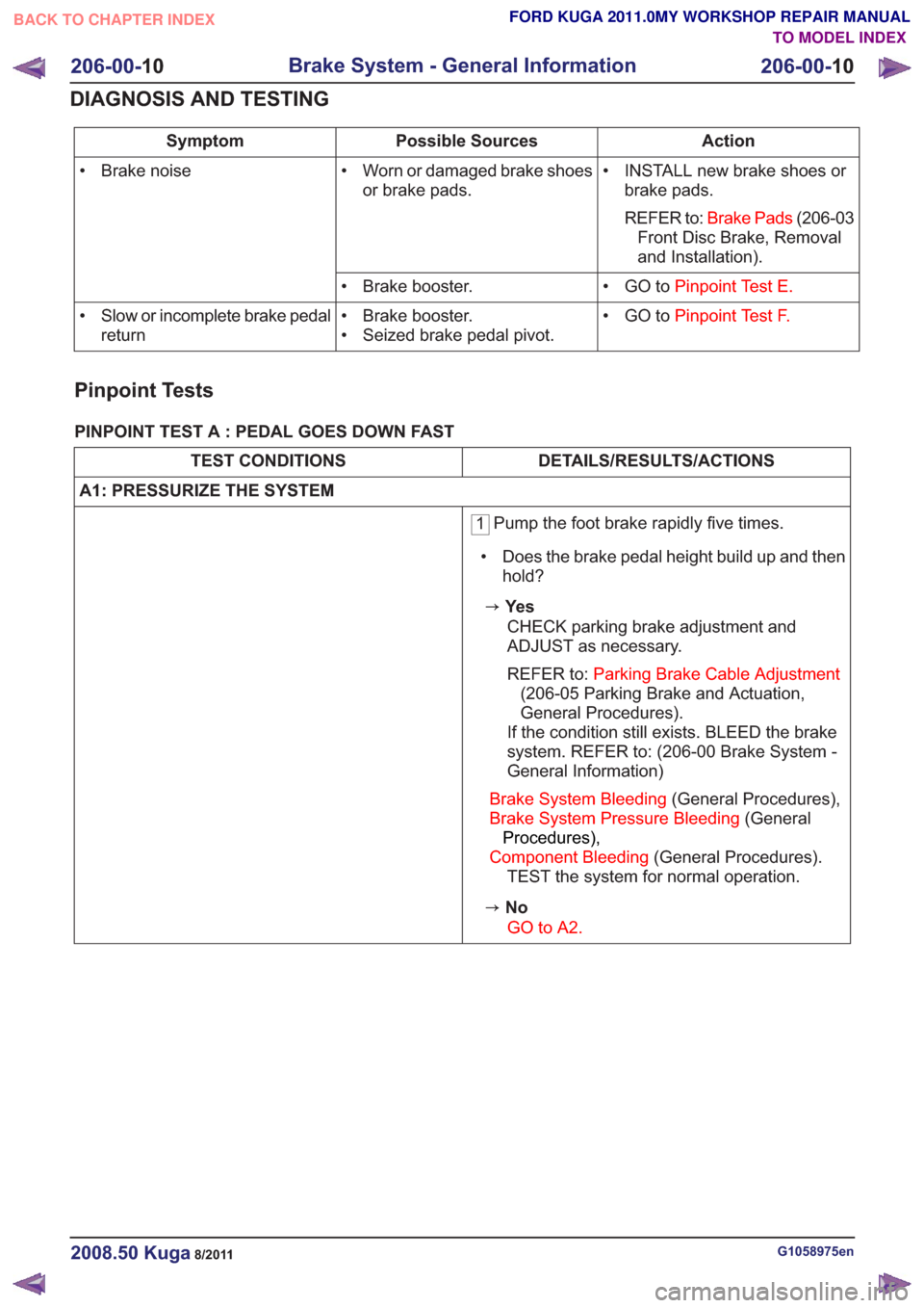
Action
Possible Sources
Symptom
• INSTALL new brake shoes orbrake pads.
REFER to: Brake Pads (206-03
Front Disc Brake, Removal
and Installation).
• Worn or damaged brake shoes
or brake pads.
• Brake noise
• GO toPinpoint Test E.
• Brake booster.
• GO toPinpoint Test F.
• Brake booster.
• Seized brake pedal pivot.
• Slow or incomplete brake pedal
return
Pinpoint Tests
PINPOINT TEST A : PEDAL GOES DOWN FAST
DETAILS/RESULTS/ACTIONS
TEST CONDITIONS
A1: PRESSURIZE THE SYSTEM
1 Pump the foot brake rapidly five times.
• Does the brake pedal height build up and then hold?
zYe s
CHECK parking brake adjustment and
ADJUST as necessary.
REFER to: Parking Brake Cable Adjustment
(206-05 Parking Brake and Actuation,
General Procedures).
If the condition still exists. BLEED the brake
system. REFER to: (206-00 Brake System -
General Information)
Brake System Bleeding (General Procedures),
Brake System Pressure Bleeding (General
Procedures),
Component Bleeding (General Procedures).
TEST the system for normal operation.
zNo
GO to A2.
G1058975en2008.50 Kuga8/2011
206-00- 10
Brake System - General Information
206-00- 10
DIAGNOSIS AND TESTING
TO MODEL INDEX
BACK TO CHAPTER INDEX
FORD KUGA 2011.0MY WORKSHOP REPAIR MANUAL
Page 1347 of 2057
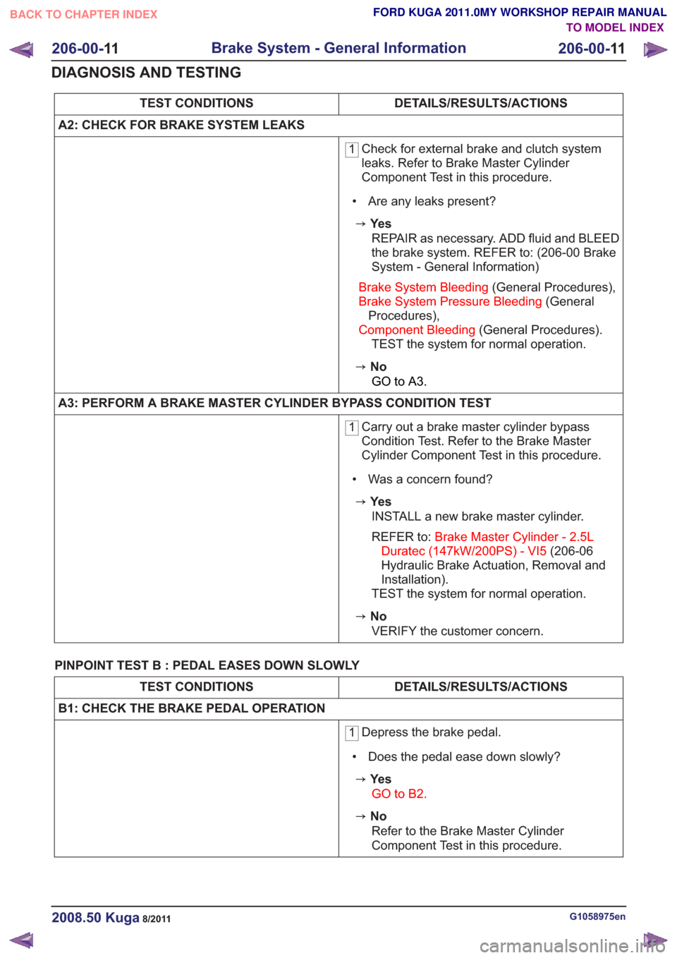
DETAILS/RESULTS/ACTIONS
TEST CONDITIONS
A2: CHECK FOR BRAKE SYSTEM LEAKS
1 Check for external brake and clutch system
leaks. Refer to Brake Master Cylinder
Component Test in this procedure.
• Are any leaks present?
zYe s REPAIR as necessary. ADD fluid and BLEED
the brake system. REFER to: (206-00 Brake
System - General Information)
Brake System Bleeding (General Procedures),
Brake System Pressure Bleeding (General
Procedures),
Component Bleeding (General Procedures).
TEST the system for normal operation.
zNo
GO to A3.
A3: PERFORM A BRAKE MASTER CYLINDER BYPASS CONDITION TEST
1 Carry out a brake master cylinder bypass
Condition Test. Refer to the Brake Master
Cylinder Component Test in this procedure.
• Was a concern found?
zYe s INSTALL a new brake master cylinder.
REFER to: Brake Master Cylinder - 2.5L
Duratec (147kW/200PS) - VI5 (206-06
Hydraulic Brake Actuation, Removal and
Installation).
TEST the system for normal operation.
zNo
VERIFY the customer concern.
PINPOINT TEST B : PEDAL EASES DOWN SLOWLY
DETAILS/RESULTS/ACTIONS
TEST CONDITIONS
B1: CHECK THE BRAKE PEDAL OPERATION
1 Depress the brake pedal.
• Does the pedal ease down slowly?
zYe s GO to B2.
zNoRefer to the Brake Master Cylinder
Component Test in this procedure.
G1058975en2008.50 Kuga8/2011
206-00- 11
Brake System - General Information
206-00- 11
DIAGNOSIS AND TESTING
TO MODEL INDEX
BACK TO CHAPTER INDEX
FORD KUGA 2011.0MY WORKSHOP REPAIR MANUAL