2011 FORD KUGA air condition
[x] Cancel search: air conditionPage 391 of 2057

Wiring Harness
General Equipment
Ford approved diagnostic tool
Inspection and Verification
1. Verify the customer concern. 2. Check the electrical connectors for security,
damage and incorrect connection. If the
electrical connectors are broken, damaged or
incorrectly connected, repair or replace the
components as required. TEST the system for
normal operation before proceeding to the next
step. 3. Disconnect the electrical connectors and check
for the following:
• Moisture in the connector due to misaligned, damaged or missing seals.
• Contamination from leaking fluids in the region of the connector. • Damaged or oxidised connector pins.
•
Disengaged connector pins (this can be checked
by carefully pressing on the individual pins).
4. If any of the conditions listed are present, repair or replace the components as required. TEST
the system for normal operation before
proceeding to the next step. G1021921en
2008.50 Kuga 8/2011 418-02-2
Wiring Harnesses
418-02-2
DIAGNOSIS AND TESTINGTO MODEL INDEX
BACK TO CHAPTER INDEX
FORD KUGA 2011.0MY WORKSHOP REPAIR MANUALE61215
Page 392 of 2057

1.
Wiring harness.
2. Component.
5. Check the wiring harness for the following:
• Incorrect routing or installed too tightly.
• Pinched or kinked sections.
• Chafed insulation.
• Security and orientation of retaining clips.
• Damage in areas where the wiring harness is subjected to noise, vibration and harshness
(NVH). For example, transmission or suspension
systems.
6. If any of the conditions listed are present, repair or replace the components as required. TEST
the system for normal operation. If the concern
persists, REFER to the digital multimeter
function of the Ford approved diagnostic tool to
check the integrity of the wiring harness and
electrical connectors. G1021921en
2008.50 Kuga 8/2011 418-02-3
Wiring Harnesses
418-02-3
DIAGNOSIS AND TESTINGTO MODEL INDEX
BACK TO CHAPTER INDEX
FORD KUGA 2011.0MY WORKSHOP REPAIR MANUALE6121621
Page 458 of 2057

Turn signals
Description
Item
External mirror housing
1
Turn signals
2
The GEM switches the direction indicators and the
direction indicator side repeaters on.
The GEM sends a signal to the instrument cluster
via the CAN bus to switch on the relevant turn
indicator and the acoustic signal.
The signals from the hazard flasher switch and
from the multifunction switch are transmitted to the
GEM via a wiring connection.
The turn signals and the warning lamp flash at a
specified frequency and, in the case of failure of a
turn signal, the frequency is doubled.
The turn signal lamps also have a one-touch lane
change function. If the multifunction lever is
pressed just slightly then the relevant turn signal
lamp is actuated 3 times by the GEM.
Interior lighting
Depending on the vehicle specification, the interior
lighting includes:
• Left and right-hand footwell lamps
• Overhead lights at front and rear
Depending on the vehicle specification, the
switchable interior lighting includes:
• Map lights
• Mirror lights in sun visors
• Glove compartment lamp
• Luggage compartment lamp
The front and rear overhead lights are switched on
by the GEM. The interior lighting is switched on if one of the
following conditions is satisfied:
One of the vehicle's doors is opened.
The ignition key is in the "0" or "I" position and the
vehicle is unlocked.
The ignition key is turned from the "II" to the "I" or
"0" position.
The interior lighting is switched off when all of the
doors are closed and one of the following
conditions is satisfied:
• 25 seconds have elapsed since the last door
was closed.
• The ignition key is turned from the "0" or "I" to the "II" position.
• The ignition key is in the "0" or "I" position while the vehicle is locked.
The dimmer function is not used if the interior
lighting is switched off via the battery protection
function.
Heated windscreen
The heated windshield is switched on by the GEM
under the following conditions:
• The heated windshield switch is operated, the ignition switch is in position "II" and the charge
warning lamp is switched off.
• The "Defrost" function of the two-zone air conditioning has been activated, the ignition
switch is in the position "II" and the charge
warning lamp is off.
• The battery voltage has exceeded 16 V for more
than 20 seconds (power management strategy).
Manual requests for switching off the heated
windshield by pressing the switch are ignored
at this time.
• The engine was started at an outside air temperature below 4°C and an engine
temperature below 65°. Manual requests for
switching off the heated windshield by pressing
the switch are accepted.
NOTE: If the battery voltage returns to the normal
range, the disabling of the heated windshield is
switched off. It is then switched off.
The heated windshield is switched off by the GEM
under the following conditions: G1030788en
2008.50 Kuga 8/2011 419-10-8
Multifunction Electronic Modules
419-10-8
DESCRIPTION AND OPERATIONTO MODEL INDEX
BACK TO CHAPTER INDEX
FORD KUGA 2011.0MY WORKSHOP REPAIR MANUAL12E98941
Page 459 of 2057

• 4 minutes have elapsed since the button for the
heated windshield was pressed.
• The ignition switch is turned to the "I" or "0" position.
• The "Defrost" function is deactivated or the switch for the heated windscreen is pressed
again while the heated windscreen is still
switched on.
• The charging system warning indicator is switched on.
• The battery voltage falls below the threshold value for low battery voltage for more than 20
seconds (power management strategy). Manual
requests for switching on the heated windshield
by pressing the switch are ignored at this time.
• More than 4 minutes have passed since starting
the engine.
Heated rear window and heated external
mirrors
The GEM transmits a request signal via the CAN
bus to the door modules to switch on the heated
exterior mirrors.
The heated rear window and the heated exterior
mirrors are switched on by the GEM under the
following conditions:
• The switch for the heated rear window is pressed and the ignition switch is in the "II"
position.
• The "defrost" function of the air conditioning is activated and the ignition switch is in the position
"II".
• The battery voltage has exceeded 16 V for more
than 20 seconds (power management strategy).
Manual requests to switch off the heated rear
window by pressing the button are ignored at
this time.
• The engine was started at an outside air temperature below 4°C and an engine
temperature below 65°. Manual requests for
switching off the heated rear window by pressing
the switch are accepted.
NOTE: If the battery voltage returns to the normal
range then the disabling of the heated rear window
is cancelled - the heated rear window is then in a
switched-off state.
The GEM transmits a request signal via the CAN
bus to the door modules to switch off the heated
exterior mirrors. The heated rear window and the heated exterior
mirrors are switched off by the GEM under the
following conditions
• 14 minutes have elapsed since the button for
the heated rear window was pressed.
• The ignition switch is turned to the position "0", "I" or "III".
• The switch for the heated rear window is pressed or the "defrost" function of the air
conditioning is deactivated while the heated rear
window is switched on.
• The battery voltage has dropped below 10.3 V for more than 20 seconds (power management
strategy). Manual requests for switching on the
heated rear window by pressing the switch are
ignored at this time.
• More than 14 minutes have passed since starting the engine.
Ambient air temperature
The ambient air temperature sensor is connected
via a cable to the GEM. It measures the outside
air temperature to an accuracy of around ±0.5 °C.
The GEM broadcasts the ambient air temperature
on the medium speed CAN bus, where it can be
evaluated by various systems.
Brake fluid level
The brake fluid level switch is connected via a
cable to the GEM.
The GEM transmits a message on the medium
speed CAN bus. The instrument cluster then
transfers this message to the high speed CAN bus
where it is made available for various other
functions.
Automatic headlamps
Refer to: Exterior Lighting (417-01 Exterior Lighting,
Description and Operation).
Combined rain sensor/light sensor
Refer to: Exterior Lighting (417-01 Exterior Lighting,
Description and Operation). G1030788en
2008.50 Kuga 8/2011 419-10-9
Multifunction Electronic Modules
419-10-9
DESCRIPTION AND OPERATIONTO MODEL INDEX
BACK TO CHAPTER INDEX
FORD KUGA 2011.0MY WORKSHOP REPAIR MANUAL
Page 1160 of 2057

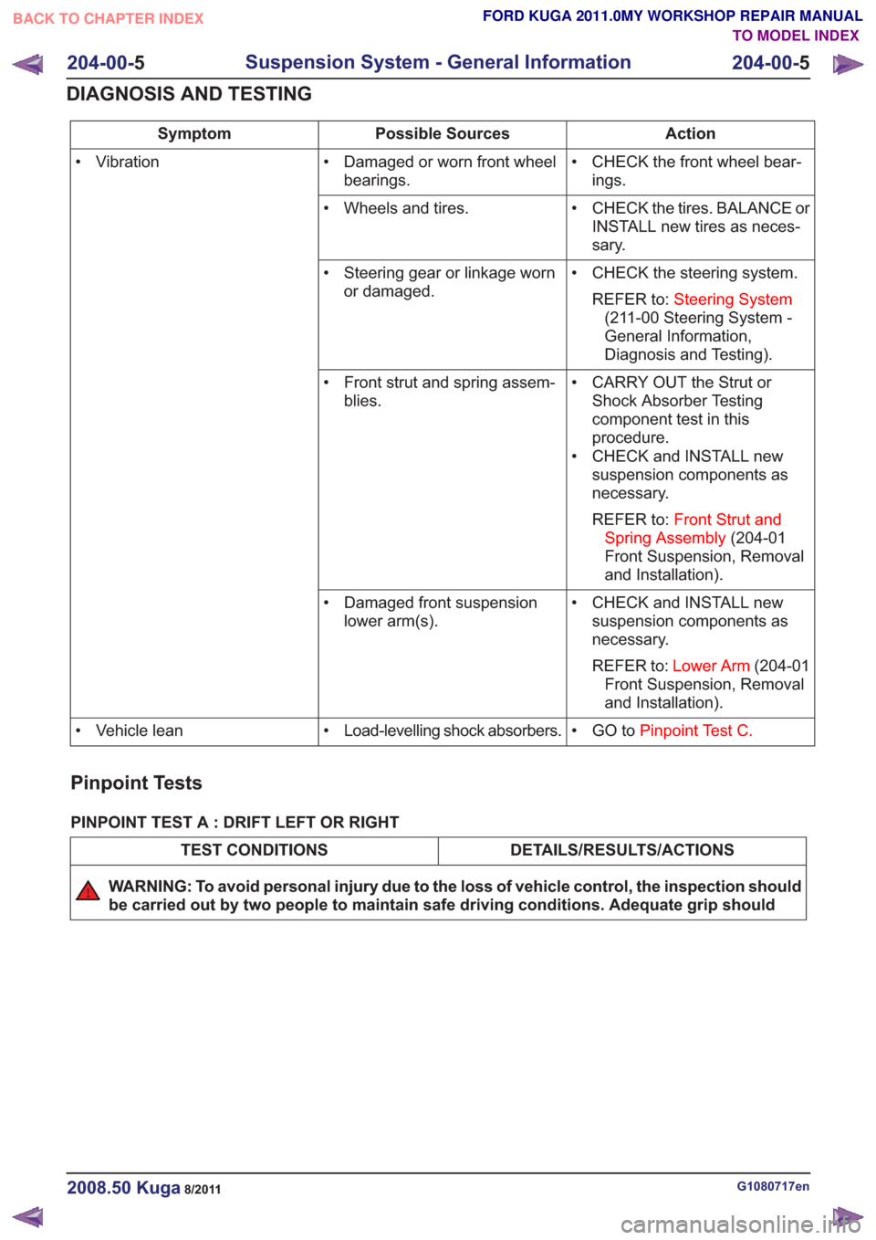
Action
Possible Sources
Symptom
• CHECK the front wheel bear-ings.
• Damaged or worn front wheel
bearings.
• Vibration
• CHECK the tires. BALANCE orINSTALL new tires as neces-
sary.
• Wheels and tires.
• CHECK the steering system.REFER to: Steering System
(211-00 Steering System -
General Information,
Diagnosis and Testing).
• Steering gear or linkage worn
or damaged.
• CARRY OUT the Strut orShock Absorber Testing
component test in this
procedure.
• CHECK and INSTALL new suspension components as
necessary.
REFER to: Front Strut and
Spring Assembly (204-01
Front Suspension, Removal
and Installation).
• Front strut and spring assem-
blies.
• CHECK and INSTALL newsuspension components as
necessary.
REFER to: Lower Arm (204-01
Front Suspension, Removal
and Installation).
• Damaged front suspension
lower arm(s).
• GO toPinpoint Test C.
• Load-levelling shock absorbers.
• Vehicle lean
Pinpoint Tests
PINPOINT TEST A : DRIFT LEFT OR RIGHT
DETAILS/RESULTS/ACTIONS
TEST CONDITIONS
WARNING: To avoid personal injury due to the loss of vehicle control, the inspection should
be carried out by two people to maintain safe driving conditions. Adequate grip should
G1080717en2008.50 Kuga8/2011
204-00- 5
Suspension System - General Information
204-00- 5
DIAGNOSIS AND TESTING
TO MODEL INDEX
BACK TO CHAPTER INDEX
FORD KUGA 2011.0MY WORKSHOP REPAIR MANUAL
Page 1161 of 2057

DETAILS/RESULTS/ACTIONS
TEST CONDITIONS
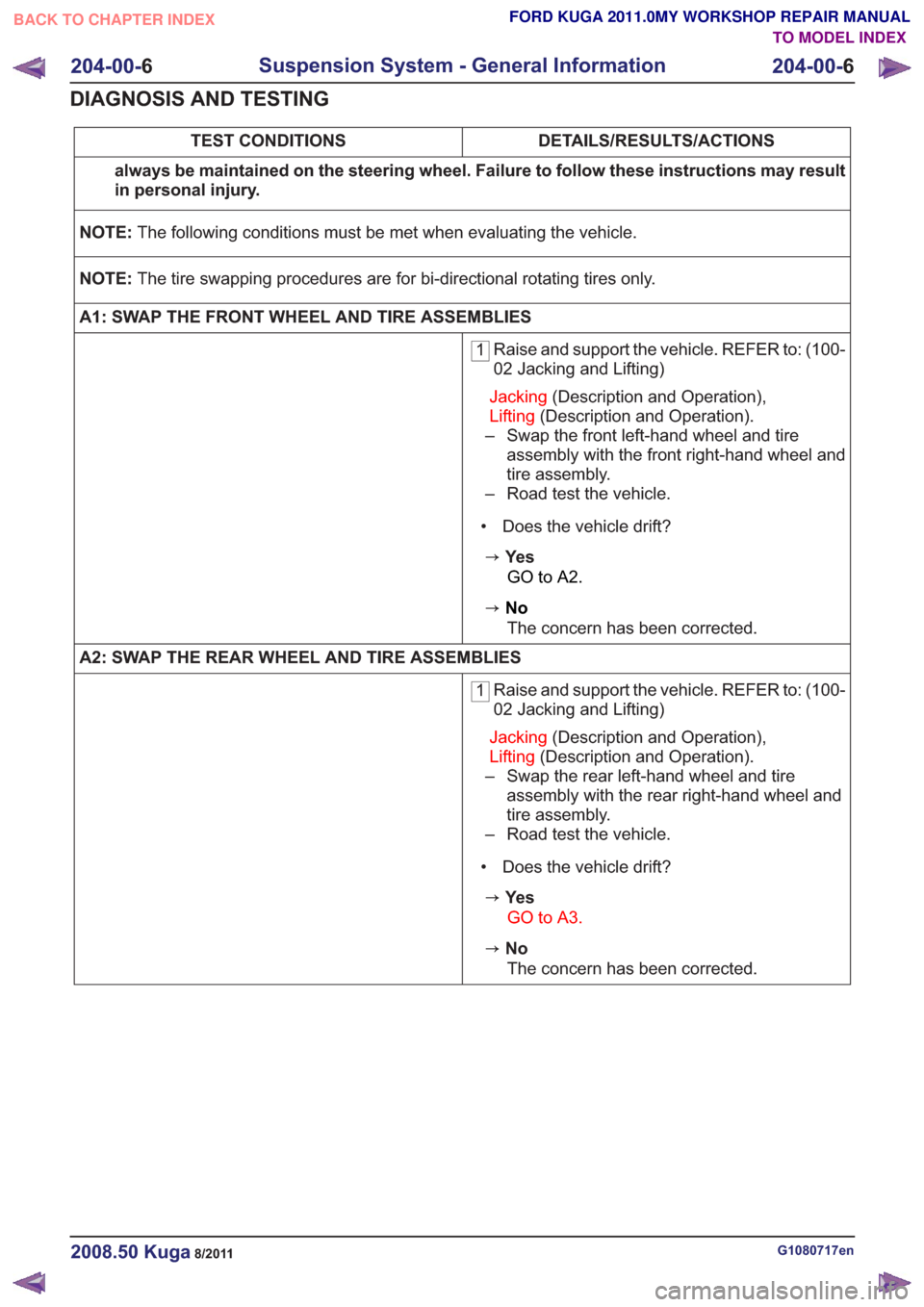
always be maintained on the steering wheel. Failure to follow these instructions may result
in personal injury.
NOTE: The following conditions must be met when evaluating the vehicle.
NOTE: The tire swapping procedures are for bi-directional rotating tires only.
A1: SWAP THE FRONT WHEEL AND TIRE ASSEMBLIES
1 Raise and support the vehicle. REFER to: (100-
02 Jacking and Lifting)
Jacking (Description and Operation),
Lifting (Description and Operation).
– Swap the front left-hand wheel and tire assembly with the front right-hand wheel and
tire assembly.
– Road test the vehicle.
• Does the vehicle drift?
zYe s GO to A2.
zNoThe concern has been corrected.
A2: SWAP THE REAR WHEEL AND TIRE ASSEMBLIES
1 Raise and support the vehicle. REFER to: (100-
02 Jacking and Lifting)
Jacking (Description and Operation),
Lifting (Description and Operation).
– Swap the rear left-hand wheel and tire assembly with the rear right-hand wheel and
tire assembly.
– Road test the vehicle.
• Does the vehicle drift?
zYe s GO to A3.
zNoThe concern has been corrected.
G1080717en2008.50 Kuga8/2011
204-00- 6
Suspension System - General Information
204-00- 6
DIAGNOSIS AND TESTING
TO MODEL INDEX
BACK TO CHAPTER INDEX
FORD KUGA 2011.0MY WORKSHOP REPAIR MANUAL
Page 1162 of 2057

DETAILS/RESULTS/ACTIONS
TEST CONDITIONS
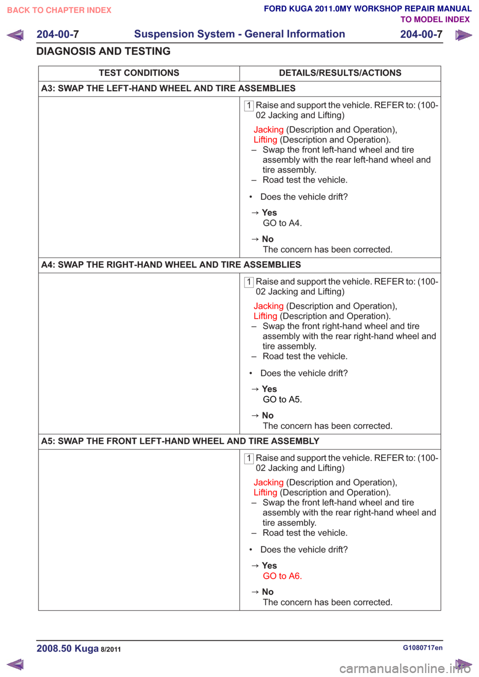
A3: SWAP THE LEFT-HAND WHEEL AND TIRE ASSEMBLIES
1 Raise and support the vehicle. REFER to: (100-
02 Jacking and Lifting)
Jacking (Description and Operation),
Lifting (Description and Operation).
– Swap the front left-hand wheel and tire assembly with the rear left-hand wheel and
tire assembly.
– Road test the vehicle.
• Does the vehicle drift?
zYe s GO to A4.
zNoThe concern has been corrected.
A4: SWAP THE RIGHT-HAND WHEEL AND TIRE ASSEMBLIES
1 Raise and support the vehicle. REFER to: (100-
02 Jacking and Lifting)
Jacking (Description and Operation),
Lifting (Description and Operation).
– Swap the front right-hand wheel and tire assembly with the rear right-hand wheel and
tire assembly.
– Road test the vehicle.
• Does the vehicle drift?
zYe s GO to A5.
zNoThe concern has been corrected.
A5: SWAP THE FRONT LEFT-HAND WHEEL AND TIRE ASSEMBLY
1 Raise and support the vehicle. REFER to: (100-
02 Jacking and Lifting)
Jacking (Description and Operation),
Lifting (Description and Operation).
– Swap the front left-hand wheel and tire assembly with the rear right-hand wheel and
tire assembly.
– Road test the vehicle.
• Does the vehicle drift?
zYe s GO to A6.
zNoThe concern has been corrected.
G1080717en2008.50 Kuga8/2011
204-00- 7
Suspension System - General Information
204-00- 7
DIAGNOSIS AND TESTING
TO MODEL INDEX
BACK TO CHAPTER INDEX
FORD KUGA 2011.0MY WORKSHOP REPAIR MANUAL
Page 1163 of 2057

DETAILS/RESULTS/ACTIONS
TEST CONDITIONS
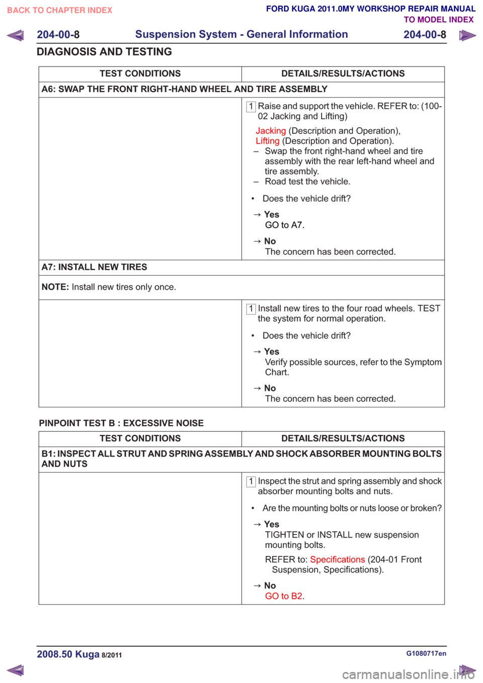
A6: SWAP THE FRONT RIGHT-HAND WHEEL AND TIRE ASSEMBLY
1 Raise and support the vehicle. REFER to: (100-
02 Jacking and Lifting)
Jacking (Description and Operation),
Lifting (Description and Operation).
– Swap the front right-hand wheel and tire assembly with the rear left-hand wheel and
tire assembly.
– Road test the vehicle.
• Does the vehicle drift?
zYe s GO to A7.
zNoThe concern has been corrected.
A7: INSTALL NEW TIRES
NOTE: Install new tires only once.
1Install new tires to the four road wheels. TEST
the system for normal operation.
• Does the vehicle drift?
zYe s Verify possible sources, refer to the Symptom
Chart.
zNoThe concern has been corrected.
PINPOINT TEST B : EXCESSIVE NOISE
DETAILS/RESULTS/ACTIONS
TEST CONDITIONS
B1: INSPECT ALL STRUT AND SPRING ASSEMBLY AND SHOCK ABSORBER MOUNTING BOLTS
AND NUTS
1 Inspect the strut and spring assembly and shock
absorber mounting bolts and nuts.
• Are the mounting bolts or nuts loose or broken?
zYe s TIGHTEN or INSTALL new suspension
mounting bolts.
REFER to: Specifications (204-01 Front
Suspension, Specifications).
zNo
GO to B2.
G1080717en2008.50 Kuga8/2011
204-00- 8
Suspension System - General Information
204-00- 8
DIAGNOSIS AND TESTING
TO MODEL INDEX
BACK TO CHAPTER INDEX
FORD KUGA 2011.0MY WORKSHOP REPAIR MANUAL