2011 FORD KUGA weight
[x] Cancel search: weightPage 17 of 2057

Instruction symbols are used to apply sealer,
lubricant, weight, tape or cleaning detergent to acomponent.
E84834
Location symbols are used to show the location of
a component or system within the vehicle.
G836098en2008.50 Kuga8/2011
100-00-
12
General Information
100-00- 12
DESCRIPTION AND OPERATION
TO MODEL INDEX
BACK TO CHAPTER INDEX
FORD KUGA 2011.0MY WORKSHOP REPAIR MANUAL
Page 1168 of 2057
3. If a new lower arm is installed it will benecessary to check and adjust the front wheel
alignment.
REFER to: Front Toe Adjustment (204-00
Suspension System - General Information,
General Procedures)
/ Rear Toe Adjustment (204-00 Suspension
System - General Information, General
Procedures).
Strut or Shock Absorber Inspection
NOTE: Inspect the struts or shock absorber for
signs of oil weepage or leaks. Make sure that the
oil is not from another source.
Weepage:
• deposits a thin film of oil on the strut and spring assembly or shock absorber.
• is normally noticed due to a collection of dust on the strut and spring assembly or shock
absorber.
• occurs during the normal running-in period of 4800 - 8050 km. After this period no new signs
of oil should be visible.
• does not require new struts or shock absorbers to be installed.
Leakage:
• covers the entire strut and spring assembly or shock absorber with oil.
• will drip oil onto the surrounding suspension components.
• requires new struts or shock absorbers to be installed.
Strut or Shock Absorber Testing
NOTE: Struts or shock absorbers must be tested
in the vertical position.
1. Remove both strut and spring assemblies or shock absorbers. The piston rods should extend.
• Disassemble the strut and spring assemblies.
REFER to: Front Strut and Spring Assembly
(204-01 Front Suspension, Removal and
Installation).
2. Compress the piston rods. Both piston rods should offer the same resistance when
compressing.
3. Compress and release the piston rods. The piston rods should extent equally. 4. Compress and pull the piston rod in the vertical
position. Feel if the resistance force at the point
of direction change-over is perceptible without
a lag. If a lag is perceptible it is an indication of
damper valve damage and new struts or shock
absorbers must be installed. REFER to:
Front Strut and Spring Assembly (204-01 Front
Suspension, Removal and Installation),
Spring (204-02 Rear Suspension, Removal and
Installation).
Load-Levelling Shock Absorber
1. With the vehicle unladen, measure and note the dimensions between the base of the wheel rim
and the top of the rear fender on both sides.
• The measurements on both sides should be approximately equal.
2. With a load of 4 average size adults and a 100 kg weight, measure and note the dimensions
between the base of the wheel rim and the top
of the rear fender on both sides.
3. NOTE: Due to the internal ratchet mechanism of the suspension components, the height
of the rear of the vehicle should rise during
the road test.
With a load of 4 average size adults and a 100
kg weight, drive the vehicle for 3 km on a road
of normal condition.
4. With a load of 4 average size adults and a 100 kg weight, measure and note the dimensions
between the base of the wheel rim and the top
of the rear fender on both sides.
5. If the dimensions on both sides are no longer approximately equal, install new load levelling
shock absorbers.
REFER to: Spring(204-02 Rear Suspension,
Removal and Installation).
6. NOTE: Due to the internal ratchet mechanism of the suspension components, the height
of the rear of the vehicle should rise during
the road test.
If the dimensions are approximately equal,
unload the vehicle and drive the vehicle for 3
km on a road of normal condition.
7. With the vehicle unladen, measure and note the dimensions between the base of the wheel rim
and the top of the rear fender on both sides.
Check the final dimensions with the original
dimensions taken in the unladen condition.
G1080717en2008.50 Kuga8/2011
204-00- 13
Suspension System - General Information
204-00- 13
DIAGNOSIS AND TESTING
TO MODEL INDEX
BACK TO CHAPTER INDEX
FORD KUGA 2011.0MY WORKSHOP REPAIR MANUAL
Page 1173 of 2057
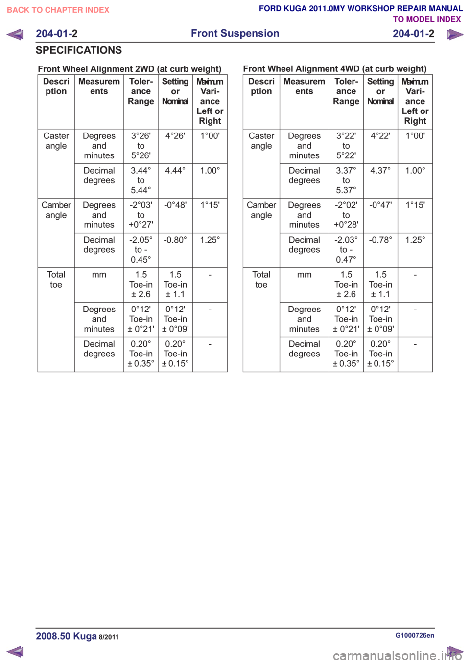
Front Wheel Alignment 2WD (at curb weight)
MaximumVari-
ance
Left or Right
Setting
or
Nominal
Toler-
ance
Range
Measurem
ents
Descri
ption
1°00'
4°26'
3°26'
to
5°26'
Degrees
and
minutes
Caster
angle
1.00°
4.44°
3.44°
to
5.44°
Decimal
degrees
1°15'
-0°48'
-2°03'
to
+0°27'
Degrees
and
minutes
Camber
angle
1.25°
-0.80°
-2.05°
to -
0.45°
Decimal
degrees
-1.5
Toe-in ±1.1
1.5
Toe-in ±2.6
mm
To t a l
toe
-
0°12'
Toe-in
± 0°09'
0°12'
Toe-in
± 0°21'
Degrees
and
minutes
-
0.20°
Toe-in
± 0.15°
0.20°
Toe-in
± 0.35°
Decimal
degrees Front Wheel Alignment 4WD (at curb weight)Maximum
Vari-
ance
Left or Right
Setting
or
Nominal
Toler-
ance
Range
Measurem
ents
Descri
ption
1°00'
4°22'
3°22'
to
5°22'
Degrees
and
minutes
Caster
angle
1.00°
4.37°
3.37°
to
5.37°
Decimal
degrees
1°15'
-0°47'
-2°02'
to
+0°28'
Degrees
and
minutes
Camber
angle
1.25°
-0.78°
-2.03°
to -
0.47°
Decimal
degrees
-1.5
Toe-in ±1.1
1.5
To e - i n ±2.6
mm
To t a l
toe
-
0°12'
Toe-in
± 0°09'
0°12'
To e - i n
±0°21'
Degrees
and
minutes
-
0.20°
Toe-in
± 0.15°
0.20°
To e - i n
±0.35°
Decimal
degrees
G1000726en2008.50 Kuga8/2011
204-01- 2
Front Suspension
204-01- 2
SPECIFICATIONS
TO MODEL INDEX
BACK TO CHAPTER INDEX
FORD KUGA 2011.0MY WORKSHOP REPAIR MANUAL
Page 1251 of 2057
Rear Drive Axle and Differential – System Operation andComponent Description
System Operation
General Information
The powertrain with all-wheel drive consists of the
following main components:
• engine
• transaxle with front axle differential
• transfer box
• halfshafts and driveshafts
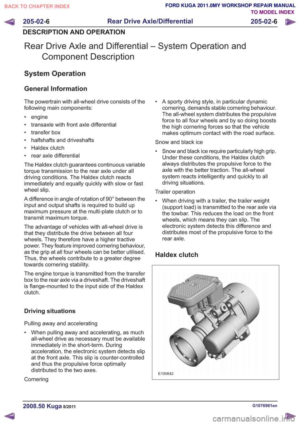
• Haldex clutch
• rear axle differential
The Haldex clutch guarantees continuous variable
torque transmission to the rear axle under all
driving conditions. The Haldex clutch reacts
immediately and equally quickly with slow or fast
wheel slip.
A difference in angle of rotation of 90° between the
input and output shafts is required to build up
maximum pressure at the multi-plate clutch or to
transmit maximum torque.
The advantage of vehicles with all-wheel drive is
that they distribute the drive between all four
wheels. They therefore have a higher tractive
power. They feature improved cornering behaviour,
as the grip at all four wheels can be better utilised.
Thus, the wheels contribute to a greater degree
towards cornering stability.
The engine torque is transmitted from the transfer
box to the rear axle via a driveshaft. The driveshaft
is flange-mounted to the input side of the Haldex
clutch.
Driving situations
Pulling away and accelerating
• When pulling away and accelerating, as muchall-wheel drive as necessary must be available
immediately in the short-term. During
acceleration, the electronic system detects slip
at the front axle. This slip is counter-controlled
and thus the propulsive force optimally
distributed to the two axes.
Cornering • A sporty driving style, in particular dynamic
cornering, demands stable cornering behaviour.
The all-wheel system distributes the propulsive
force to all four wheels and by so doing boosts
the high cornering forces so that the vehicle
makes optimum contact with the road surface.
Snow and black ice
• Snow and black ice require particularly high grip. Under these conditions, the Haldex clutch
always distributes the propulsive force to the
axle with the better traction. The all-wheel
system reacts intelligently and quickly to all
driving situations.
Trailer operation
• When driving with a trailer, the trailer weight (support load) is transmitted to the rear axle via
the towbar. This reduces the load on the front
wheels, which means they can slip. The
electronic system detects this difference and
distributes most of the propulsive force to the
rear axle.
Haldex clutch
E100642
G1076981en2008.50 Kuga8/2011
205-02- 6
Rear Drive Axle/Differential
205-02- 6
DESCRIPTION AND OPERATION
TO MODEL INDEX
BACK TO CHAPTER INDEX
FORD KUGA 2011.0MY WORKSHOP REPAIR MANUAL
Page 1340 of 2057
Brake System
General EquipmentPressure/vacuum gauge set
The Ford approved diagnostic tool
The brake system operates by transferring effort
applied to the brake pedal by the driver to the
brakes at each wheel.
The braking effort is distributed to each wheel,
using a hydraulic system. The system is assisted
using a vacuum brake booster that reduces pedal
effort and increases hydraulic pressure.
The parking brake operates on the rear wheels
and is applied using a hand operated control.
Inspection and Verification
NOTE: Before carrying out any diagnosis, make
sure that the brake system warning indicator is
functional.
1. Verify the customer concern.
2. Visually inspect for obvious signs of mechanical or electrical damage.
Visual Inspection Chart
Electrical
Mechanical
• Electricalconnector(s)
• Wiring harness(s)
• Switch(es)
• Tire pressure(s)
• Wheels and tires
• Fluid leak(s)
3. If an obvious cause for an observed or reported concern is found, correct the case (if possible)
before proceeding to the next step.
4. If the cause if not visually evident, verify the symptom and refer to the Symptom Chart.
Road Test
Carry out a road test to compare actual vehicle
braking performance with the performance
standards expected by the driver. The ability of the
test driver to make valid comparisons and detect
performance deficiencies will depend on
experience.
The driver should have a thorough knowledge of
the brake system operation and accepted general performance guidelines to make good comparisons
and detect performance concerns.
An experienced technician will always establish a
route that will be used for all brake diagnosis road
tests. The road selected will be reasonably smooth
and level. Gravel or bumpy roads are not suitable
because the surface does not allow the tires to grip
the road equally. Crowned roads should be avoided
because of the large amount of weight shifted to
the low set of wheels on this type of road. Once
the route is established and consistently used, the
road surface variable can be eliminated from the
test results.
Before a road test, get a complete description of
the customer concerns or suspected condition.
From the description, the technician will be able to
match possible causes with symptoms. Certain
components will be identified as possible sources
while others will be eliminated by the evidence.
More importantly, the customer description can
reveal unsafe conditions which should be checked
or corrected before a road test. The description will
also help form the basic approach to the road test
by narrowing the concern to specific components,
vehicle speed or conditions.
Begin the road test with a general brake
performance check. Using the description of the
concern, test the brakes at different vehicle speeds
using both light and heavy pedal pressure.
Determine if the concern is in the front or rear
braking system. First use the foot brake and then
the parking brake. If the condition (i.e. pull,
vibration, pulsation) occurs only on operation of
the parking brake, the concern is in the rear brake
system. If the condition occurs when the foot brake
is depressed, the concern is in the front brake
system.
Avoid locking the brakes and sliding the tires. This
condition will not indicate brake efficiency. A heavily
braked but turning wheel will stop the vehicle in a
shorter distance than locked wheels.
If the concern becomes evident during this check,
make sure it fits the description given before the
road test. If the concern is not evident, attempt to
duplicate the condition using the information from
the description.
If a concern exists, use the Brake System Symptom
Chart in order to isolate it to a specific sub-system
and condition description. From this description, a
list of possible sources can be used to further
G1058975en2008.50 Kuga8/2011
206-00-
4
Brake System - General Information
206-00- 4
DIAGNOSIS AND TESTING
TO MODEL INDEX
BACK TO CHAPTER INDEX
FORD KUGA 2011.0MY WORKSHOP REPAIR MANUAL
Page 1830 of 2057
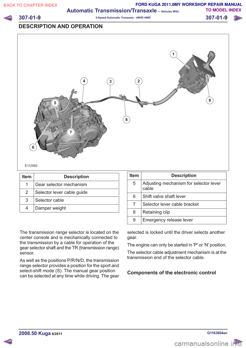
1
234
5
6
8
9
7
E112582
Description
Item
Gear selector mechanism
1
Selector lever cable guide
2
Selector cable
3
Damper weight
4Description
Item
Adjusting mechanism for selector lever
cable
5
Shift valve shaft lever
6
Selector lever cable bracket
7
Retaining clip
8
Emergency release lever
9
The transmission range selector is located on the
center console and is mechanically connected to
the transmission by a cable for operation of the
gear selector shaft and the TR (transmission range)
sensor.
As well as the positions P/R/N/D, the transmission
range selector provides a position for the sport and
select-shift mode (S). The manual gear position
can be selected at any time while driving. The gear selected is locked until the driver selects another
gear.
The engine can only be started in 'P' or 'N' position.
The selector cable adjustment mechanism is at the
transmission end of the selector cable.
Components of the electronic control
G1163604en2008.50 Kuga8/2011
307-01-
9
Automatic Transmission/Transaxle
— Vehicles With:
5-Speed Automatic Transaxle - AW55 AWD
307-01- 9
DESCRIPTION AND OPERATION
TO MODEL INDEX
BACK TO CHAPTER INDEX
FORD KUGA 2011.0MY WORKSHOP REPAIR MANUAL
Page 1933 of 2057
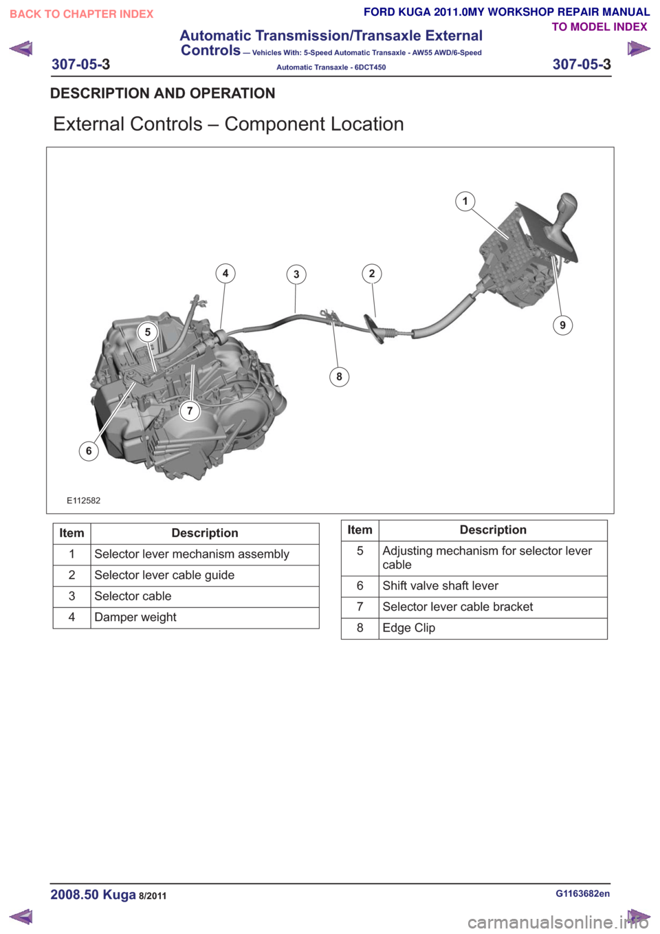
External Controls – Component Location
1
234
5
6
8
9
7
E112582
Description
Item
Selector lever mechanism assembly
1
Selector lever cable guide
2
Selector cable
3
Damper weight
4Description
Item
Adjusting mechanism for selector lever
cable
5
Shift valve shaft lever
6
Selector lever cable bracket
7
Edge Clip
8
G1163682en2008.50 Kuga8/2011
DESCRIPTION AND OPERATION
TO MODEL INDEX
BACK TO CHAPTER INDEX
FORD KUGA 2011.0MY WORKSHOP REPAIR MANUAL
307-05-
3
Automatic Transmission/Transaxle External
Controls
— Vehicles With: 5-Speed Automatic Transaxle - AW55 AWD/6-Speed
Automatic Transaxle - 6DCT450
307-05-3
.