Page 81 of 195

DOORS
Before opening a door,
ensure that you can do
so in safe conditions.
WARNING
FROM OUTSIDE
Opening: turn the key to position 1-
fig. 75 and pull the opening handle.
Closing: turn the key to position 2.
fig. 75
F0X0051m
fig. 76
F0X0052m
FROM INSIDE
Opening: pull opening lever A-fig. 76.
Closing: close the door and press
the lever.
CENTRAL LOCKING
From outside
With the doors closed, insert and
turn the key in a door lock.From inside
With doors closed, press (to lock)
or pull (to unlock) one of the door
opening levers.
The remote control can also be used
to activate central locking.
IMPORTANT If one of the doors is
not fully closed or there is a system
failure, central locking will not
operate and, after several attempts,
the system will be excluded for
about 30 seconds.
The doors can be locked or
unlocked during this period, without
the intervention of the electronic
system. After the 30 seconds have
elapsed, the control unit is ready to
receive commands again.
If the cause of operational failure has
been removed, the device will
resume normal operation.
Otherwise, the exclusion cycle will
be repeated.
79
Page 82 of 195
fig. 76
F0X0056m
fig. 77
F0X0057m
OPENING WINDOWS
Electric fig. 76
(for versions/markets,
where provided)
Two switches are located in the
driver side door panel moulding.
These operate the following
windows with ignition key at MAR:
A - left window;
B - right window.
There is a switch in the passenger
side door handle which controls the
passenger side window.
Press the switches to lower the
windows. Lift to raise them.
Incorrect use of the
electric windows may
be dangerous. Before and
during their operation ensure
that passengers are not at risk
from the moving glass, either
by personal objects caught in
the mechanism or struck by it
directly. When leaving the car,
always remove the ignition key
to avoid the risk of injury due
to accidental operation of the
electric windows.
WARNINGManual fig. 77
(for versions/markets, where
provided)
Operate the appropriate control
handles A to lower/raise the
window.
80
Page 83 of 195

fig. 78
F0X0058m
fig. 79
F0X0060m
fig. 80
F0X0061m
SUN ROOF
Some long cab versions may be
equipped with tilting sun roof which
can also be completely removed
according to ventilation
requirements inside the cab.
Tilting function
Turn the ring nut in fig. 78 in the
direction indicated, so that the sun
roof can be opened to the desired
position.
When the device is opened as far as
possible, the ring nut will be vertical.Removing glass from sun roof
The following steps describe the sun
roof glass removal procedure. This
operation must be carried out with
extreme caution, so that the glass
does not fall and result in damage:
– move the sun roof to the
maximum opening position;
– release the red stop fig. 79,
applying light pressure as indicated
(this operation must be carried out
using the end of the screwdriver in
the tool bag, located under the
passenger seat);– from the luggage compartment,
remove the glass from the sun roof
and detach it from its front housing,
pulling it backwards;
– insert the sun roof glass, using the
tilting ring nut located near the
luggage compartment in the space
between the rear window and the
protective mesh; then slide it
between the two guides provided, as
illustrated in fig. 80;
– lock the sun roof glass to the
protective mesh with the rubber
strap A provided;
81
Page 84 of 195
The glass of the sun
roof may be damaged if
not fixed correctly to the
protective mesh with the
dedicated strap.
WARNING
To refit the sun roof glass, carry out
the removal procedure in reverse,
making sure that it is correctly
inserted into both the front housing
and the stop fig. 79. Apply light
pressure to the back of the glass,
until it clicks into place; then rotate
the ring nut fig. 78 twice (in the
opposite direction to that for
opening).
fig. 81
F0X0062m
Before setting off,
check that the sun roof
glass is locked correctly, also by
pressing lightly on the internal
part.
WARNINGLOAD COMPARTMENT
To open the rear flap:
– insert the key in the lock A-fig. 81
and turn it anticlockwise;
– press the Fiat logo at point B
while pulling part C of the logo,
then guide the flap down with one
hand.
82
Page 85 of 195

While lowering the flap,
do not put your hands
in the mechanism: risk of
pinching and/or injury.
WARNING
To get the most out of the load
compartment, the flap can be
removed (the assistance of another
adult is advised); proceed as follows:
– remove the retaining devices
A-fig. 82 (one per side) for the
side rods;
A
fig. 82
F0X0063m
fig. 83
F0X0064m
– position the flap at 45°;
– remove the flap, pulling in the
direction of the arrow fig. 83.
Pay attention to your
hands, both when
removing the flap and when
refitting. Risk of pinching
and/or injury.
WARNING
Before setting off, make
sure:
– that the side safety rods are
refitted correctly
– that the flap is inserted
correctly in its housing;
– that you test the flap by
opening and closing (also
with the key).
WARNING
If the flap is fitted
incorrectly, it is a
danger both to you and to
others.
WARNING
Comply with the
current legislation
regarding the transport of
loads. NEVER use the load
compartment for people
transport.
WARNING
83
Page 86 of 195

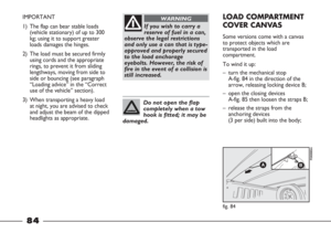
If you wish to carry a
reserve of fuel in a can,
observe the legal restrictions
and only use a can that is type-
approved and properly secured
to the load anchorage
eyebolts. However, the risk of
fire in the event of a collision is
still increased.
WARNINGIMPORTANT
1) The flap can bear stable loads
(vehicle stationary) of up to 300
kg; using it to support greater
loads damages the hinges.
2) The load must be secured firmly
using cords and the appropriate
rings, to prevent it from sliding
lengthways, moving from side to
side or bouncing (see paragraph
“Loading advice” in the “Correct
use of the vehicle” section).
3) When transporting a heavy load
at night, you are advised to check
and adjust the beam of the dipped
headlights as appropriate.
Do not open the flap
completely when a tow
hook is fitted; it may be
damaged.
LOAD COMPARTMENT
COVER CANVAS
Some versions come with a canvas
to protect objects which are
transported in the load
compartment.
To wind it up:
– turn the mechanical stop
A-fig. 84 in the direction of the
arrow, releasing locking device B;
– open the closing devices
A-fig. 85 then loosen the straps B;
– release the straps from the
anchoring devices
(3 per side) built into the body;
fig. 84
F0X0065m
84
Page 87 of 195
– wind up the canvas in the
direction of the cab;
– lock the wound up canvas against
the cab using the elastic bands
provided A-fig 86;
fig. 85
F0X0066m
fig. 86
F0X0067m
– loosen the screws of the
positioning blocks A-fig. 87 (2 per
side) then slide the two
crosspieces B along the grooves in
the body to the desired position;
– retighten the screws of the blocks A.
fig. 87
F0X0068m
fig. 88
F0X0069m
BONNET
To open the bonnet:
1) Pull lever A-fig. 88.
Perform this operation
only when the vehicle is
stationary.
WARNING
Before opening the
bonnet, check that the
wiper arms are not lifted from
the windscreen.
WARNING
85
Page 88 of 195
2) Use lever A-fig. 89 to raise the
bonnet, holding it centrally and
releasing the bonnet stay A-fig. 90
from its locking device at the
same time.
3) Insert the end of the stay in
bonnet housing B.
Warning. The bonnet
may drop suddenly if
the bonnet stay is not
positioned correctly.
WARNING
A
fig. 89 fig. 90
F0X0070m
A
BF0X0071m
Be careful when
working inside the
engine compartment with the
engine hot to avoid burning
yourself. Do not place your
hands near the fan, as it may
be activated even when the key
is not in the ignition. Wait for
the engine to cool.
WARNING
Pay attention to
scarves, ties and other
loose-fitting garments. If they
accidentally come into contact
with moving parts, they may
get caught up and dragged
with serious risks for those
wearing them.
WARNING
86