Page 137 of 195

135
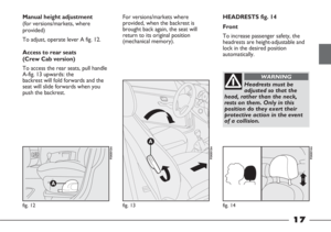
FUSE SUMMARY TABLE
Device protected No. Fuse Amps Location
F12
F13
F31
F32
F35
F37
F38
F39
F42
F43
F44
F47
F48
F49
F50
F51
F5315A
15A
7,5A
15A
10A
10A
20A
15A
7,5A
30A
20A
30A
30A
7,5A
7,5A
7,5A
10Afig. 143
fig. 143
fig. 143
fig. 143
fig. 143
fig. 143
fig. 143
fig. 143
fig. 143
fig. 143
fig. 143
fig. 143
fig. 143
fig. 143
fig. 143
fig. 143
fig. 143
ARight dipped headlight
Left dipped headlight, headlight alignment corrector
Supply for reversing light, relay switch coils on engine compartment
fuse box, manual climate control system
+30 exterior lighting control supply
Brake light switch supply (NC signal)
Brake lights, instrument panel node
Central locking
+30 supply for roof light, glove compartment light, radio
ABS control unit
Windscreen wiper, two-way pump
Power socket - cigar lighter
Front left electric window
Front right electric window
+15 services supply for radio, electric mirrors, central and side
control panel lighting, electric mirror control lighting
Airbag system
+ supply for number plate lights, heater control lighting,
power socket – cigar lighter lighting, radio lighting
Direction indicators, hazard warning lights, instrument panel node
Page 138 of 195

136
Device protected No. Fuse Amps Location
F00
F01
F02
F03
F04
F06
F07
F08
F10
F11
F14
F15
F16
F17
F18
F19
F20
F21
F23
F24
F3060A
70A
40A
20A
50A
30A – 40A (*)
40A – 60A (*)
40A
15A
15A
10A
10A
7,5A
10A
7,5A
7,5A
20A
15A
15A
10A
15A
Plug preheating
Dashboard fuse box - basic
Dashboard fuse box - optional
Ignition switch
Anti-slip system
Single speed – Radiator fan first speed
Single speed – Radiator fan second speed
Climate control fan
Horn
Speedometer generator, canister solenoid valve, preheating
control unit, secondary loads, engine management system
Right main beam headlight
Left main beam headlight
Engine management control unit, engine management
system relay switch, engine cooling system remote control switch
Engine management control unit (supply), diesel pump solenoid
valve unit
Engine management control unit
Climate control compressor
Heated filter
Fuel pump, cut-off system
Additional headlights
Ignition-operated +15 positive pole
Fog lights
(*) For versions/markets, where provided.fig. 145
fig. 145
fig. 145
fig. 145
fig. 145
fig. 145
fig. 145
fig. 145
fig. 145
fig. 145
fig. 145
fig. 145
fig. 145
fig. 145
fig. 145
fig. 145
fig. 145
fig. 145
fig. 145
fig. 145
fig. 145
Page 139 of 195

137
IF THE BATTERY
RUNS DOWN
First of all, you are advised to
consult the “Vehicle maintenance”
section, which contains a list of
precautions to prevent the battery
from running down and ensure long
battery life.
RECHARGING THE BATTERY
IMPORTANT The battery
recharging procedure is given for
information purposes only. You are
advised to contact a Fiat Dealership
to have this operation performed.
Charging should be slow at a low
ampere rating for approximately 24
hours. Charging for a longer time
may damage the battery.To recharge, proceed as follows:
– disconnect the negative battery
terminal;
– connect the charger cables to the
battery terminals, observing the
polarity;
– switch on the charger;
– when it is recharged, turn the
charger off before disconnecting it
from the battery;
– reconnect the negative battery
terminal.
Battery fluid is
poisonous and
corrosive: avoid contact with
skin and eyes. The battery
should be charged in a well
ventilated place, away from
naked flames or possible
sources of sparks: danger of
explosion and fire.
WARNING
Do not attempt to
charge a frozen battery:
it must be thawed first,
otherwise it may explode.
If freezing has occurred, the
battery should be checked by
skilled personnel to make sure
that the internal elements are
not damaged and that the
body is not cracked, with the
risk of leaking poisonous and
corrosive acid.
WARNING
Page 140 of 195
138
IF THE VEHICLE
MUST BE RAISED
WITH THE JACK
See paragraph “If a tyre is
punctured”, in this section.
The jack is only to be
used for replacing
wheels on the vehicle with
which it is provided.Never use
the jack for other purposes, such
as lifting other vehicles. Never
use the jack to carry out
repairs under the vehicle.
WARNING
Incorrect positioning of
the jack may cause the
raised vehicle to fall. Do not
use the jack for loads greater
than that indicated on the jack
itself.
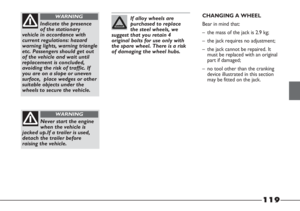
WARNINGBear in mind that:
– the jack requires no adjustment;
– the jack cannot be repaired; in the
event of a fault it must be replaced
by another original one;
– no tool other than the cranking
device illustrated in this section may
be fitted on the jack.
Page 141 of 195
139
The vehicle must not be
raised from the rear
(lower part of bodywork or
suspension components) nor
must it be raised from the front
(gearbox casing).
WARNINGWITH WORKSHOP LIFT
Laterally
The vehicle must be raised with the
arm of the hydraulic lift positioned
as illustrated in fig. 146 and 147.
fig. 146
F0X0129m
fig. 147
F0X0130m
fig. 148
F0X0131m
WITH LIFT ARMS
The vehicle must be raised with the
ends of the arms in the lower points
in the bodywork as indicated in
fig. 148.
Make sure that the arms
of the lift do not put a
strain on the bodywork
or the side trim. Adjust the arms
of the lift correctly, and apply a
wooden or rubber block if
necessary.
Page 142 of 195

140
Before towing, turn the
ignition key to MAR
and then to STOP without
extracting it. If the key is
removed, the steering lock will
activate automatically and it
will be impossible to steer the
wheels.
WARNING
The tow hook must be
used exclusively for
roadside assistance operations.
You are allowed to tow the
vehicle for short distances using
an appropriate device in
accordance with the highway
code (rigid bar), to move the
vehicle on the road in readiness
for towing or transport via a
breakdown vehicle. The tow
hook MUST NOT be used to
tow vehicles off the road or
where there are obstacles
and/or for towing operations
using cables or other non-rigid
devices. In compliance with the
above conditions, towing must
take place with the two
vehicles (one towing, the other
towed) aligned as much as
possible along the same centre
line.
WARNING
fig. 149
F0X0132m
IF THE VEHICLE
MUST BE TOWED
The vehicle can only be towed at the
front.
The tow hook is supplied with the
vehicle.
It is located in the tool bag.
How to attach the tow hook:
1) Take the tow hook.
2) Remove the cover on the front
bumper fig. 149, prising it up using
a screwdriver in the notch on the
cover.
3) Fully tighten the ring on the
threaded pin.
Page 143 of 195
141
Before screwing on the
tow hook, clean the
threaded pin thoroughly.
Before towing the vehicle,
make sure that the tow ring is
fully screwed onto the
threaded pin.
WARNING
Do not start the engine
whilst the vehicle is
being towed.
WARNING
The brake servo and
power steering will not
work while the vehicle is being
towed. You will therefore need
to apply more force to the brake
pedal and steering wheel. Do
not use flexible cables when
towing and avoid jerky
movements. During towing
operations, make sure that the
fixing of the joint does not
damage adjoining components.
WARNINGEXTINGUISHER
(for versions/markets,
where provided)
Some versions may feature an
extinguisher A-fig. 152.
For use and maintenance, follow the
instructions on the extinguisher
itself.
fig. 152
F0X0135m
Page 144 of 195
page intentionally left blank