Page 25 of 260

cursor appears on the left in front of these
lected values.
By pressing the
I Reset I button , you activate
the selection you made or confirm the values
you set.
Selected functions are identified with
a check mark or are carried out d irectly.
Meanings of the symbols in the display:
Se lee- Selected tune- Meaning
tion tion
bar
> Cursor Current Selection
..f
Check mark Selected or Fune-
tion active
D
Box Not selected
•
Triangle point- Previous page
ing up
T
Triangle point- Next page
ing down
Selecting settings
The Driver Information System settings are
menu -guided.
Fig. 15 Dis play: Men u Set tings , computer selected
(p age 1)
Select your settings as follows:
.,. Press the !R eset ! button. The Start menu ap
pears
!:!) page 21, fig. 12 .
.. Press the rocker switch until Set is dis
played .
.. Press the lReset ! button . All the menus ap
pear .
.. Press the rocker switch until the des ired line
is highlighted (cursor)
I:!) fig . 15 .
.,. Press the I Reset ! button .
Driver in format ion syste m 23
.. If necessary, scroll by selecting and activat
ing the symbol for "Next page" or "Previous
page".
When you have selected the Computer menu
and activated it by pressing the
I R eset! but
ton, two computer levels appear (computer 1
and computer 2). Now you have to select the level you want using the rocker switch and ac
tivate it with the
I Reset ! button .
Efficiency program
Description
Applies to veh icles: w ith tr ip computer with efficiency
program
--[II 300m,
27.7 mpg
25.8 mpg
Fig. 16 D isplay: efficie ncy prog ra m
.. Press the I RESET ! button @ c> page 21,
fig . 11
repeatedly until the efficiency pro
gram appears in the display .
The efficiency program can help you to use
less fuel.
It evaluates driving information in
reference to fuel consumption and shows oth
er equipment influencing consumption as well
as shift recommendations . Fuel economy
messages ¢
page 24 provide tips for effi
c ient driving.
The efficiency program uses distance and con
sumption data from trip computer
1. If the
data are deleted in the efficiency program,
those values are also reset in trip computer
1.
Page 26 of 260

24 Driver information system
Other equipment
Applies to vehicles: with trip computer w ith eff iciency
program
Fig. 17 Dis pl ay : o th er equ ipm ent
• In the effic iency program, press the funct ion
selection switch
r::;, page 21, fig. 11 @ re
peatedly until the other equipment appears
in the disp lay.
Other equipment that is currently affecting
fuel consumption is listed in the efficiency program . The display shows up to three other
items of equipment ®· The equipment using
the most fuel is listed first. If more than three
items using fuel are switched on, the equip
ment that is currently using the most fuel is
d isplayed .
A scale @also shows the current total con
sumption of all other equipment .
Fuel economy messages
Applies to vehicles: with trip computer with efficiency
program
Fig. 18 Dis play: fuel eco nomy message
Fuel economy messages are displayed when
fuel consumption is inc reased by certain con
ditions. If you follow these fuel economy mes
sages, you can reduce your vehicle's consump
tion of fuel. The messages appear automati- cal
ly and are only d isplayed in the efficiency
program. The fuel economy messages turn off
automat ica lly after a certain per iod of t ime.
• To turn a fuel economy message off immedi
ately after it appears, press the
I RESET ! but
ton
r::;, page 21 , fig. 11 @, or
.. Press the funct ion select ion sw itch
r::;, page 21, fig. 11 @ .
@ Tips
- Once you have turned a fuel economy
message off, it will on ly appear again af
ter you turn the ignition on again.
- The fue l economy messages are not dis
played in every instance, but rather in in
tervals over a period of time.
Service interval display
The service interval display reminds you when
your next service is due .
Fig. 19 Section of instrument clus ter: Se rv ice interva l
d isplay
The service interval display determines when
a service procedure is needed for your veh icle .
It operates in two stages:
- Service reminder: Before reaching a service
event, this message appears briefly when
you switch on the ignition: Oil change in
1230 mi (2000 km) 150 days.
- Service event: When the date for service is
reached, the message Oil change! appears.
It is accompanied by an audible signal.
Display remaining distance
By briefly pulling the knob, ®
<=>page 10,
fig. 3, the distance/time remaining to the
next service date is displayed with the ignition
IIJ,-
Page 27 of 260
.
I f the d istance/ time remaining is called up on
new vehicles or after service has been per
formed, the")
on. The distance/time remaining is updated
every 300 mi les (500 km).
I f the d istance/ time remaining is called up on
new vehicles or after service has been per
formed, the due date is always shown in the
disp lay with
Oil change in----- m i (km)- -
d ay s
within the first 300 miles (500 km).
To reset the display
The dealersh ip perfo rming the service resets
the disp lay whe n the service has been com
p leted . The display is resets as follows :
- Switch the ignition on.
- Pull the knob @
Q page 10, fig. 3, this mes-
sage appears:
Oil chang e!
- Pull the knob u ntil t he d isplay O il change in
--- --mi (km )··· day s
appears in the display.
If the reset button is not p ulled within
5
seconds, the display reset mode closes .
(D Tips
-If a malfunction is p resen t (red symbol),
the distance remaining cannot be ca lled
u p.
- Do not reset the display between service
intervals . Do ing so will res ult in an in co r
r ect displ ay.
- If the batte ry is d iscon nected, the Serv
i ce Interval Disp lay val ues are ret ained .
-If service was not performed at the co r
re ct time or the service interval display
w as not reset a fter service w as per
fo rmed, the add itiona l mi leage driven or
the elapsed days wi ll be shown as nega
tive numbers.
Lap timer
Introduction
App lies to vehicles: with lap timer
You ca n record and evaluate lap times with
the lap timer in the display
¢page 25,
fig . 21 . The time is measu red in minutes, sec
onds and 1/10 seconds. The hou rs a re also
shown when the lap time exceeds 60 minutes .
The maximum individual measurement is 99
hours.
Dr iver in formation system 25
A WARNING
Please devote your full attention to driv
i ng. As the driver, you have complete re
spons ib ility for safety in traffic. Only use
the functions in such a way that you a lways
maintai n comple te control over you r ve hi
cle in a ll traffic situations.
(D Tips
When the lap time r stopwatch is running ,
you can ca ll up the tr ip comp ute r informa
tion with the
I RESET I but to n.
Calling up the lap timer and timing
Applies to vehicles: wi th lap timer
---- @
Fig. 20 Co ntrols
F ig. 21 Display : Lap t imer
Calling up the lap t imer
... Press the I RESET !¢ fig . 20 @ button until
the lap timer ¢
fig. 21 appears.
Timing laps
.,. To start timing, press the upper section o f
the wiper switch @. The time measurement
is shown in line
(D ¢ fig. 21.
.,. To stop timing, press the upper section of
the wiper switch @again. This also starts
timing the next round. The previous time ..,_
Page 28 of 260
 shows the current lap
number , for example LAP 5.
Displaying intermediate time and pausi")
26 Driver information system
moves one line up, first to line @ and then
to line @. Line @) shows the current lap
number , for example LAP 5.
Displaying intermediate time and pausing
timing
• To display an intermediate time, press the
lower section of the wiper switch @. T he in
termediate time appears in line
(D and is
marked with".
• To pause tim ing, pres s the lower section of
the wiper switch @again .
• To continue t iming, press the upper section
of the wiper switch @.
If timing is paused, you can co ntinue it later
even if you switch the ign it ion off .
Evaluating times and continuing or
resetting timing
Applies to vehicles: with lap timer
You can evaluate the fastest, slowest and
average lap times.
LAP 5
+ 45:12.9
59:08.B
0 51:10.B
Fig. 22 Dis play : lap time eva lua tion
• To eva luate lap times, press and hold the
I RESE T I~ page 25, fig . 20 @ button for ap
proximate ly 2 seconds. The disp lay shows
the fastest lap" +", the slowest lap"-" and
the average lap time "0".
• To continue t iming for add itional laps, press
the wiper switch @.
• To reset the timer to zero , press and hold
the
I RESE T! button again for approximately
2 seconds .
• To switch the lap timer off comp letely, press
the
I RESE T! button briefly.
(D Tips
-Saved lap times cannot be individually
de leted from the total results.
- The saved lap t imer va lues wi ll not be
lost after turning the ignition off.
Speed warning system
Overview
The speed warning system helps you to keep
your driving speed below a set speed limit.
The speed warning system warns the driver if
he exceeds a previously stored maximum
speed . A warning tone will sound as soon as
the vehicle speed exceeds the set speed by
about 3 mph (3 km/h). At the same time, a
warning symbol appears in the display.
The speed warning system has
two warning
thresholds that function independently of
each other and that have somewhat different
purposes:
Speed warning 1
You can use speed warning 1 to set the maxi
mum speed while you are driving . This setting
will remain in effect until you turn off the ign i
t io n, assuming that you have not changed o r
reset the setting.
The speed warn ing symbol
[i (USA models)/
IDl (Canada models) in the warning 1 display
appears when you exceed the maximum
speed.
It goes out when the speed falls below
the stored maximum speed .
The speed warn ing symbol will also go out if
the speed
exceeds the stored maximum speed
by more than about 25 mph (40 km/h) for at
least 10 seconds. The stored maximum speed
is deleted.
Setting speed warning 1
~page 27 .
Speed warning 2
Storing warning 2 is recommended if you al
ways
want to be rem inded of a certain speed,
for example when you are travel ing in a coun
try that has a general maximum speed limit, .,..
Page 29 of 260
/
laJ (Canada models) appears in the dis
p lay when you")
or if you do not want to exceed a specified
speed for w inter t ires.
The speed warning 2 symbol,
1mj (USA mod
e ls)/
laJ (Canada models) appears in the dis
p lay when you exceed the stored speed lim it.
Unlike war ning 1, it will not go out until the
ve hicle speed drops be low the stored speed
limit.
Sett ing speed warning 2
c:> page 2 7 .
(0 Tips
Even t ho ugh yo ur vehicle is equipped with
a speed warning sys tem, yo u shou ld st ill
watch the speedomete r to make sure you
are not driving faster than the speed limit.
Speed warning 1: setting a speed limit
Warning threshold 1 is s et by the button.
F ig. 23 Sec tio n of ins trume nt clus ter: Set/Check but
to n
Storing the maximum speed
• Drive a t the desi red max imum speed.
• Press the knob button¢
fig. 23 until the
speed wa rning symbo l
[I (U SA mode ls)l [°i
(Canad a mode ls) appears .
Resetting the maximum speed
• Drive the vehicle at a speed of at least
3 mph (5 km/h)
• Press the knob fo r more than 2 seconds.
T he speed warning symbo l
[I (U SA mode ls)/
t•) (Canada models) will appear b riefly in t he
d isp lay when you re lease the button to indi
cate that the max imum speed has been stored
successfully.
Dr iver in formation system 2 7
The maximum speed rema ins stored until it is
c hanged by pressing the button again b rief ly
or unti l it is deleted by a lengthy push on the
button .
Speed warning 2: setting a speed limit
Switches in the wiper arm are used to operate warning threshold 2 .
-----@
Fig. 2 4 Wipe r leve r: T rip comp uter co ntrols
To store maximum speed
• Turnoff the igni tion .
• Briefly press the button in the instrument
cluste r
c:> page 2 7 , fig . 23 . The odomete r
and the digital clock a re now illum inated .
• Press the b utton for at least 2 se co nds. The
curren tly s to red max imum spee d appears in
the display
or t h e crossed o ut symbol for
warni ng thresho ld 2, if no maximum speed
was set previously .
• Press the f unction selector switch in the
wiper lever @
c:> fig. 24 up or down to
change the set va lue. Values run up or down
in steps of 6 .2 mph (10 km/h) .
To delete ma ximum speed
• Turnoff the ignit ion.
• Briefly press the button in the instrument
cluster
c:> page 2 7 , fig . 23 . The odometer
and the digital clock are now illum inated .
• Press the b utton fo r at least 2 seconds . The
current ly sto red max imum speed appears in
t he display .
• Press the reset button in the wipe r lever @
c:> fig. 24 unt il the crosse d ou t speed warn
ing sym bo l for warning thresho ld 2 a ppears
in the display.
~
Page 30 of 260

28 Driv e r in formation sy stem
A few seconds after the adjustment is com
p leted, the illumination for the odometer and
the dig ital clock will go o ut.
@ Tips
This warning threshold can also be con
trolled through the trip computer
~page 22, Navigating the menu.
On-Board Diagnostic
system (OBD)
On-Board Diagnostics
Fig. 25 Locat ion of Data Link Connecto r (DLC)
On-Board Diagnostics monitors the compo
nents of you r emission control system. Each
monitored compo nen t in your eng ine system
has been assigned a code . In case of a ma l
function, the component will be identified
and the fau lt stored as a code in the control
module memory.
The MIL light may a lso illuminate if there is a
leak in the on-board fue l vapor recovery sys
tem .
If the light illuminates after a refuelling,
stop the vehicle and make sure the fuel filler
cap is properly closed ¢
page 176.
In o rder to make an accurate diagnosis, the
stored data can only be displayed using spe
cia l diagnostic equipment (generic scan tool
for OBD).
I n o rder to connect the special diagnostic
equipment, push the plug into the Data Link
Connector (DLC). The DLC is located to the
right of the hood release¢
fig. 25.
Your authorized Audi dea ler or a qualified
service station can interpret the code and per
form the necessary repair .
Malfunction Indicator lamp (MIL)
The Malfunction Indicator Lamp (MIL) &'I in
the instrument cluster¢
page 13, fig. 6 is
part of the On-Board Diagnostic COBO II) sys
tem .
The warning/indicator light illuminates when
the ignit io n is switched on and goes out after
the e ngine starts and the idle has stabilized.
Th is indicates that the MIL is working prope r
ly.
If th e light d oes not go out after the engine
is started, or illum inates wh ile you are dr iv
ing, a malfunc tion may exist in the engine sys
tem.
If the light illum inates, the catalytic con
verte r could be damaged .
Continue driving
with reduced p ower (avoid
ing sustained high speeds and/or rapid accel
erations) and have the cond ition corrected.
Contact you r authorized Audi dea le r.
If the light illum inates, the electronic speed
limi ter may also be malfunct ioning . For more
i nformation ¢
page 28, Electronic speed
limiter.
An improperly clo sed fu el filler cap ma y also
cau se the MIL light to illuminate
¢ page 176.
Electronic speed limiter
Your vehicle may be factory eq uipped w ith
tires that are rated for a maximum speed of 130 mph (210 km/h) . This is less than the
maximum speed of your vehicle. To reduce the
risk of sudden tire fai lure and loss of control if
the vehicle is operated at excessive speeds,
your vehicle a lso has an electronic speed limit
er . The electronic speed limiter prevents your
vehicle from going faster than the tire speed
rating. Fo r more information
¢page 205. ...,
Page 31 of 260

Ill will illum inate . If th is oc
curs, contact the nearest")
If the engine control unit receives fau lty vehi
cle roadspeed signa ls , the Ma lfunction Indica
tor Light (MIL)
Ill will illum inate . If th is oc
curs, contact the nearest authori zed Audi
dealer for assistance.
S mod els
Your vehicle 's top speed is e lectronically limit
ed to 155 mph (250 km/h).
If the engine control unit rece ives fa ulty vehi
cle roadspeed signa ls , the Ma lfunction Indica
tor Lamp (MIU ¢• will i lluminate. If this oc
curs, contact the nearest authorized Audi
dea ler for assistance.
A WARNING
-
Always observe the posted speed limits
and adjust your speed to suit prevailing
road, traff ic and weather conditions. Never
drive your vehicle faster than the maxi
mum speed rating of the tires insta lled.
Warnings and symbols
Red symbols
A red symbol means DANGER
" Pull of the road and stop the veh icle .
"T urn off the engine.
" Check the ma lf u nction ing system. Contact
your autho rized Audi dea le r o r a qualified
workshop for assistance.
- USA models : Malfunction in the
brake system ¢
page 30
---·--
D
Canada models : Malfunction in the
brake system ¢
page 30
Engine coolant level too low/
engine coolant temperature too
high
r:1;> page 31
Engine oil pressure too low
¢page 31
Clutch is overheat ing
c:1;> page 92
Dr iver in formati on sys tem 29
When a red symbol appears, a warning tone
will sound
three times in succession . The sym
bo l cont inues to flash unti l the malfunction
has been repaired. If there is
more than one
malfunc tion, the symbo ls appear one after
the other for about two seconds .
(D Tips
- The message for a malfunction can be
shown by pressing on the left knob.
- Dur ing route guidance on vehicles with a
navigation system, the warn ing symbol
is shown in the field above.
Yellow symbols
A yellow symbol means WARNING.
Ii
Low fuel leve l
¢page32
- -- Check engine oil level
151!1 ¢page 32
- Engine oil sensor malfunction
l:ill ¢ page 32
Worn brake pads
¢page32
USA models : Speed warning 1
c:1;> page 3 2
Canada models : Speed warning 1
¢page32
USA models: Speed warning 2
c:1;> page 3 3
Canada models: Speed warning 2
c:1;> page 33
Dynamic headlight range contro l*
defective
¢ page 33
-Engine speed limitation *
c:1;> page 33
Windshield washer fl ui d leve l low
c:1;> page 33
Page 32 of 260

30 Driv e r in formation sy stem
Battery voltage too high or too low
¢page33
Defective light bu lb
Qpage 33
USA models: Defective brake light
Qpage33
Canada models: Defective brake
light
Q page 33
Light/rain sensor defective (automat
ic headlights) * defective
Q page 3 4
Adaptive Light* defective
¢page34
Tire pressure monitoring system
¢page212
When a yellow symbol appears, a warning
tone will sound
once. Check the d isp layed
f u nction as soon as possib le. If
more than one
malfunction is detected, a ll symbols will ap
pear one after the other for abou t two sec
onds.
Driver information
In addition to th e warning/indicator lights
a nd the symbols in the inst rument cluster dis
play, driver information is displayed.
F ig . 2 6 Section of instrument cluster: Set/Check b ut
ton
Driver information appea rs in the disp lay
when a defec tive l ight bu lb is reported by the
defect ive light bulb warning¢
page 33,
when the brake p ads are wo rn and before you
engage a gear. In add
ition, driver information may appear
whe n a red symbo l flashes in the driver dis
play .
To display Driver information
As an examp le, the . symbo l appears in the
display. If yo u now p ress the button¢
fig. 26,
the following driver message appears in the display:
Switch off engine and che ck oil level
The driver message in the display goes out af
te r about 5 seconds. Yo u can display t he drive r
message aga in by briefly pres sing the button.
BRAKE /(©) Brake system
The indicator light flashes if the brake fluid
level is too low, if there is a malfunction in
t he ABS sys tem o r when the parking brake is
engaged.
If the - (USA models),1111 (Canada
model s) symbo l flashes in the d isplay w it h t he
par king brake rele ase d, there is a mal func tion
in the brake system. In ad dition to the sym
bo l, one o f two messages appears in the dis
play :
STOP V ehicle and check brake fluid
ABS fault! See Owner's manual
.,. Pull off the road a nd stop the veh icle .
.,. Obtain profess iona l assistance.
USA models: if t here is a ma lf u nction in the
ABS system, the
mES warning/indicator light
illuminates along with the -system
malfu nction warning/ind icator light
Q .&. .
Canada models: if there is a mal function in
the ABS system, the
ti] warning/ indicator
light illum inates together with the . brake
system mal function warn ing/indicator light
Q .&_ .
Parking brake set
The parking brake war ning light -·
(Canada mode ls) illum inates when the park
i ng brake is set. In addition, a warn ing tone
will sound after yo u have driven for longer
 1
1 2
2 3
3 4
4 5
5 6
6 7
7 8
8 9
9 10
10 11
11 12
12 13
13 14
14 15
15 16
16 17
17 18
18 19
19 20
20 21
21 22
22 23
23 24
24 25
25 26
26 27
27 28
28 29
29 30
30 31
31 32
32 33
33 34
34 35
35 36
36 37
37 38
38 39
39 40
40 41
41 42
42 43
43 44
44 45
45 46
46 47
47 48
48 49
49 50
50 51
51 52
52 53
53 54
54 55
55 56
56 57
57 58
58 59
59 60
60 61
61 62
62 63
63 64
64 65
65 66
66 67
67 68
68 69
69 70
70 71
71 72
72 73
73 74
74 75
75 76
76 77
77 78
78 79
79 80
80 81
81 82
82 83
83 84
84 85
85 86
86 87
87 88
88 89
89 90
90 91
91 92
92 93
93 94
94 95
95 96
96 97
97 98
98 99
99 100
100 101
101 102
102 103
103 104
104 105
105 106
106 107
107 108
108 109
109 110
110 111
111 112
112 113
113 114
114 115
115 116
116 117
117 118
118 119
119 120
120 121
121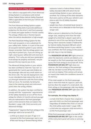 122
122 123
123 124
124 125
125 126
126 127
127 128
128 129
129 130
130 131
131 132
132 133
133 134
134 135
135 136
136 137
137 138
138 139
139 140
140 141
141 142
142 143
143 144
144 145
145 146
146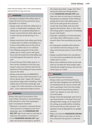 147
147 148
148 149
149 150
150 151
151 152
152 153
153 154
154 155
155 156
156 157
157 158
158 159
159 160
160 161
161 162
162 163
163 164
164 165
165 166
166 167
167 168
168 169
169 170
170 171
171 172
172 173
173 174
174 175
175 176
176 177
177 178
178 179
179 180
180 181
181 182
182 183
183 184
184 185
185 186
186 187
187 188
188 189
189 190
190 191
191 192
192 193
193 194
194 195
195 196
196 197
197 198
198 199
199 200
200 201
201 202
202 203
203 204
204 205
205 206
206 207
207 208
208 209
209 210
210 211
211 212
212 213
213 214
214 215
215 216
216 217
217 218
218 219
219 220
220 221
221 222
222 223
223 224
224 225
225 226
226 227
227 228
228 229
229 230
230 231
231 232
232 233
233 234
234 235
235 236
236 237
237 238
238 239
239 240
240 241
241 242
242 243
243 244
244 245
245 246
246 247
247 248
248 249
249 250
250 251
251 252
252 253
253 254
254 255
255 256
256 257
257 258
258 259
259