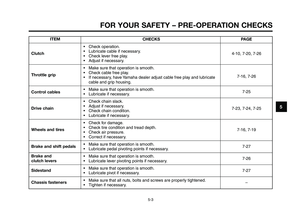
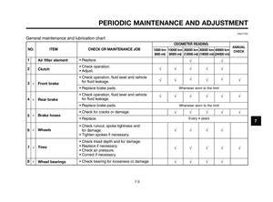
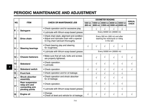
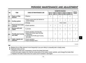
Page 49 of 100
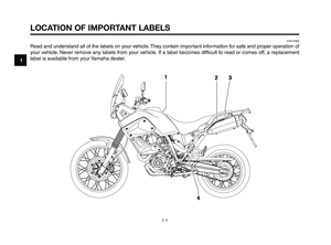
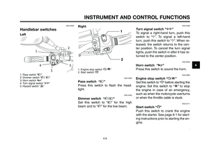
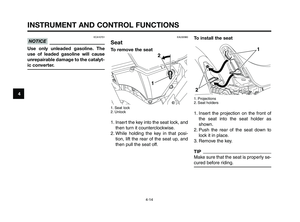
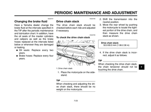
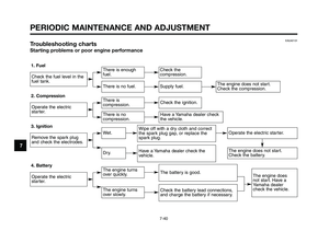
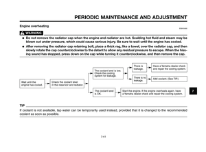
1
2
3
4
5
6
7
8
9
10
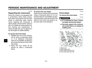
PERIODIC MAINTENANCE AND ADJUSTMENT
7-7
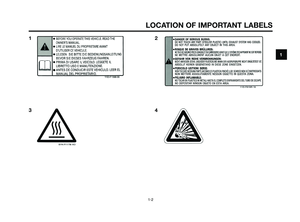
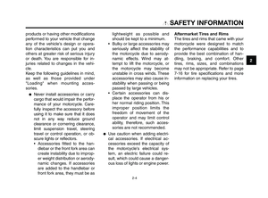
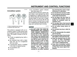
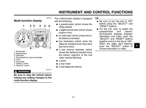
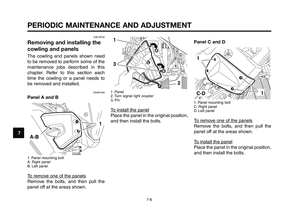
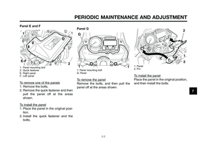
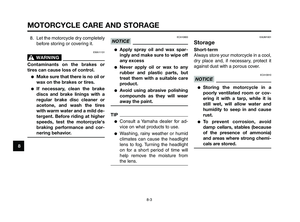
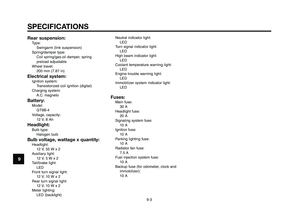
Panel E and F
1. Panel mounting bolt
2. Quick fastener
E. Right panel
F. Left panel
To remove one of the panels
1. Remove the bolts.
2. Remove the quick fastener and then
pull the panel off at the areas
shown.
To install the panel
1. Place the panel in the original posi-
tion.
2. Install the quick fastener and the
bolts.
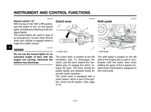
11
2E-F
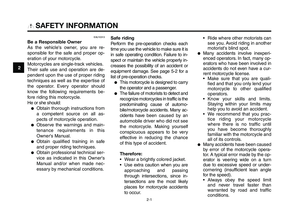
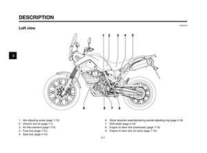
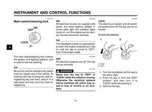
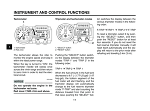
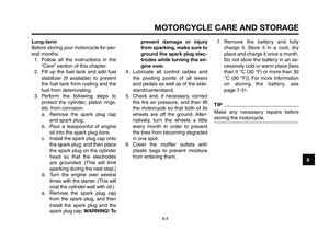
Panel G
1. Panel mounting bolt
G. Panel
To remove the panel
Remove the bolts, and then pull the
panel off at the areas shown.
1. Panel
2. Pin
To install the panel
Place the panel in the original position,
and then install the bolts.
2
2
1
XT660Z 05-07 ING-AUS:MY03 04-06 ING 11-05-2009 10:09 Pagina 7-7
Page 50 of 100

PERIODIC MAINTENANCE AND ADJUSTMENT
7-8
1
2
3
4
5
6
7
8
9
10
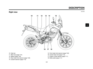
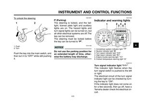
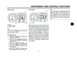
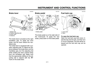
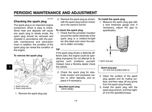
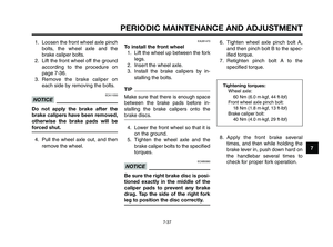
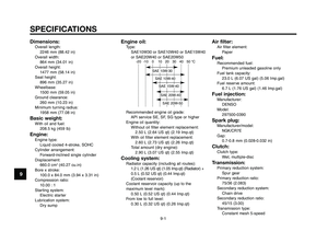
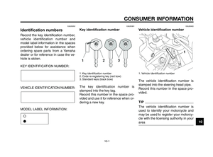
2. Remove the spark plug as shown,
with the spark plug wrench includ-
ed in the owner’s tool kit.
To check the spark plug
1. Check that the porcelain insulator
around the center electrode of the
spark plug is a medium-to-light
tan (the ideal color when the vehi-
cle is ridden normally).
TIP
If the spark plug shows a distinctly dif-
ferent color, the engine could be oper-
ating improperly. Do not attempt to di-
agnose such problems yourself.
Instead, have a Yamaha dealer check
the vehicle.
2. Check the spark plug for elec-
trode erosion and excessive car-
bon or other deposits, and re-
place it if necessary.
Specified spark plug:
CR7E (NGK)
Spark plug gap:
0.7-0.8 mm (0.028-0.032 in)
To install the spark plug
1. Measure the spark plug gap with
a wire thickness gauge and, if
necessary, adjust the gap to
specification.
1. Spark plug gap
2. Clean the surface of the spark
plug gasket and its mating sur-
face, and then wipe off any grime
from the spark plug threads.
3. Install the spark plug with the
spark plug wrench, and then tight-
en it to the specified torque.
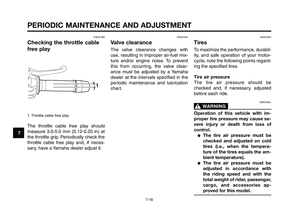
EAU19603
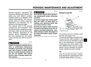
Checking the spark plug
The spark plug is an important engine
component, which is easy to check.
Since heat and deposits will cause
any spark plug to slowly erode, the
spark plug should be removed and
checked in accordance with the peri-
odic maintenance and lubrication
chart. In addition, the condition of the
spark plug can reveal the condition of
the engine.
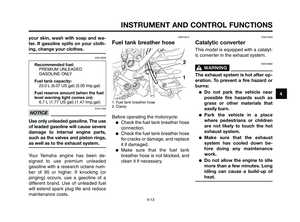
To remove the spark plug
1. Spark plug cap
2. Spark plug wrench
1. Remove the spark plug cap.
XT660Z 05-07 ING-AUS:MY03 04-06 ING 11-05-2009 10:09 Pagina 7-8
Page 51 of 100

1
2
3
4
5
6
7
8
9
10
PERIODIC MAINTENANCE AND ADJUSTMENT
7-9
EAUB1560
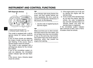
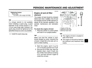
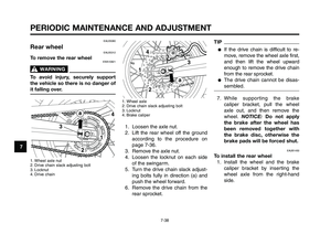
Engine oil and oil filter
element
The engine oil level should be checked
before each ride. In addition, the oil must
be changed and the oil filter element re-
placed at the intervals specified in the
periodic maintenance and lubrication
chart.
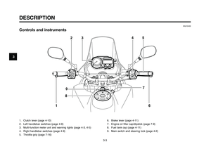
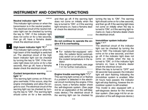
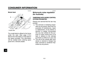
To check the engine oil level
1. Place the vehicle on a level surface
and hold it in an upright position.
TIP
Make sure that the vehicle is posi-
tioned straight up when checking the
oil level. A slight tilt to the side can re-
sult in a false reading.
2. Start the engine, warm it up for
10-15 minutes and then turn it off.
3. Remove the oil filler cap, wipe the
dipstick clean, insert it back into
the oil filler hole (without screwing
it in), and then remove it again to
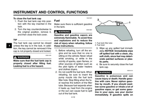
check the oil level.
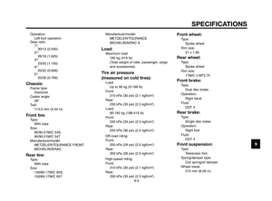
1. Engine oil filler cap
2. Maximum level mark
3. Minimum level mark
TIP
●The engine oil tank is located in-
side of the frame.
●The engine oil should be between
the minimum and maximum level
marks.
Tightening torque:
Spark plug:
12.5 Nm (1.25 m·kgf, 9.0 ft·lbf)
TIP
If a torque wrench is not available
when installing a spark plug, a good
estimate of the correct torque is 1/4-
1/2 turn past finger tight. However, the
spark plug should be tightened to the
specified torque as soon as possible.
4. Install the spark plug cap.
XT660Z 05-07 ING-AUS:MY03 04-06 ING 11-05-2009 10:09 Pagina 7-9
Page 52 of 100

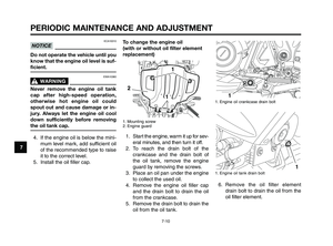
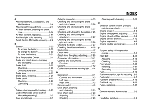
1. Mounting screw
2. Engine guard
1. Start the engine, warm it u")
PERIODIC MAINTENANCE AND ADJUSTMENT
7-10
1
2
3
4
5
6
7
8
9
10
To change the engine oil
(with or without oil filter element
replacement)
1. Mounting screw
2. Engine guard
1. Start the engine, warm it up for sev-
eral minutes, and then turn it off.
2. To reach the drain bolt of the
crankcase and the drain bolt of
the oil tank, remove the engine
guard by removing the screws.
3. Place an oil pan under the engine
to collect the used oil.
4. Remove the engine oil filler cap
and the drain bolt to drain the oil
from the crankcase.
5. Remove the drain bolt to drain the
oil from the oil tank.
1. Engine oil crankcase drain bolt
1. Engine oil tank drain bolt
6. Remove the oil filter element
drain bolt to drain the oil from the
oil filter element.
1
ECA10010
NOTICE
Do not operate the vehicle until you
know that the engine oil level is suf-
ficient.
EWA10360
WARNING0
Never remove the engine oil tank
cap after high-speed operation,
otherwise hot engine oil could
spout out and cause damage or in-
jury. Always let the engine oil cool
down sufficiently before removing
the oil tank cap.
4. If the engine oil is below the mini-
mum level mark, add sufficient oil
of the recommended type to raise
it to the correct level.
5. Install the oil filler cap.
XT660Z 05-07 ING-AUS:MY03 04-06 ING 11-05-2009 10:09 Pagina 7-10
Page 53 of 100

Oil filter element drain bolt:
10 Nm (1.0 m·kgf, 7.2 f")
1
2
3
4
5
6
7
8
9
10
PERIODIC MAINTENANCE AND ADJUSTMENT
7-11
Tightening torques:
Oil filter element cover bolt:
10 Nm (1.0 m·kgf, 7.2 ft·lbf)
Oil filter element drain bolt:
10 Nm (1.0 m·kgf, 7.2 ft·lbf)
Tightening torques:
Engine oil drain bolt (crankcase):
30 Nm (3.0 m·kgf, 22 ft·lbf)
Engine oil drain bolt (oil tank):
18 Nm (1.8 m·kgf, 12.9 ft·lbf)
13. Add the specified amount of the
recommended engine oil, and
then install and tighten the oil filter
cap. 10. Install the oil filter element drain
bolt.
11. Tighten the oil filter element cover
bolts and the oil filter element
drain bolt to their specified
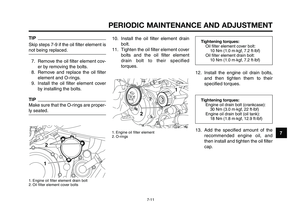
torques.1. Engine oil filter element
2. O-rings
12. Install the engine oil drain bolts,
and then tighten them to their
specified torques.
TIP
Skip steps 7-9 if the oil filter element is
not being replaced.
7. Remove the oil filter element cov-
er by removing the bolts.
8. Remove and replace the oil filter
element and O-rings.
9. Install the oil filter element cover
by installing the bolts.
TIP
Make sure that the O-rings are proper-
ly seated.
1. Engine oil filter element drain bolt
2. Oil filter element cover bolts
2
1
XT660Z 05-07 ING-AUS:MY03 04-06 ING 11-05-2009 10:09 Pagina 7-11
Page 54 of 100
 (1.67 Imp.qt)
of the recommended engine oil.
Then, start the engine, race it 5 o")
ECAM1060CAUTION:
The engine oil tank must be filled in
2 steps. First, fill the engine oil tank
with 1.90 L (2.0 US qt) (1.67 Imp.qt)
of the recommended engine oil.
Then, start the engine, race it 5 or 6
times, turn it off, and then add the
remainder of the engine oil.
NOTE:
Be sure to wipe off spilled oil on any
parts after the engine and exhaust
system have cooled down.
ECA11620CAUTION: � In order to prevent clutch slip-
page (since the engine oil also
lubricates the clutch), do not
mix any chemical additives. Do
not use oils with a diesel speci-
fication of “CD” or oils of a
higher quality than specified. In
addition, do not use oils la-
beled “ENERGY CONSERVING
II” or higher.
� Make sure that no foreign ma-
terial enters the crankcase.
14. Start the engine, and then let it idle for several minutes while
checking it for oil leakage. If oil is
leaking, immediately turn the en-
gine off and check for the cause.
15. Turn the engine off, and then check the oil level and correct it if
necessary.
16. Install the engine guard by in- stalling the screws.
EAU20070
Coolant
The coolant level should be checked
before each ride. In addition, the
coolant must be changed at the inter-
vals specified in the periodic mainte-
nance and lubrication chart.
EAU20253
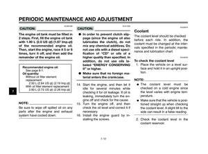
To check the coolant level1. Place the vehicle on a level sur- face and hold it in an upright posi-
tion.
NOTE:
�The coolant level must be
checked on a cold engine since
the level varies with engine tem-
perature.
�Make sure that the vehicle is posi-
tioned straight up when checking
the coolant level. A slight tilt to the
side can result in a false reading.
2. Check the coolant level in the coolant reservoir.
Recommended engine oil:See page 8-1.
Oil quantity: Without oil filter element
replacement:2.50 L (2.64 US qt) (2.19 Imp.qt)
With oil filter element replacement: 2.60 L (2.73 US qt) (2.26 Imp.qt)
PERIODIC MAINTENANCE AND ADJUSTMENT
7-12
7
03 ingles -australia 3/5/10 06:00 Página 54
Page 55 of 100

1
2
3
4
5
6
7
8
9
10
PERIODIC MAINTENANCE AND ADJUSTMENT
7-13
TIP
The coolant should be between the
minimum and maximum level marks.
1. Coolant reservoir
2. Maximum level mark
3. Minimum level mark
4. Reservoir cap
3. If the coolant is at or below the
minimum level mark, remove pan-
el E (See page 7-7.), remove the
reservoir cap, add coolant to the
maximum level mark, and then in-
stall the reservoir cap and the
panel. WARNING! Remove only
the coolant reservoir cap. Nev-
er attempt to remove the radia-
tor cap when the engine is hot.
NOTICE:If coolant is not avail-
able, use distilled water or soft
tap water instead. Do not use
hard water or salt water since it
is harmful to the engine. If wa-
ter has been used instead of
coolant, replace it with coolant
as soon as possible, otherwise
the cooling system will not be
protected against frost and
corrosion. If water has been
added to the coolant, have a
Yamaha dealer check the an-
tifreeze content of the coolant
as soon as possible, otherwise
the effectiveness of the coolant
will be reduced.
Coolant reservoir capacity
(up to the maximum level mark):
0.50 L (0.52 US qt) (0.44 Imp.
EAU33031
Changing the coolant
The coolant must be changed at the
intervals specified in the periodic
maintenance and lubrication chart.
Have a Yamaha dealer change the
coolant. WARNING! Never attempt
to remove the radiator cap when
the engine is hot.
XT660Z 05-07 ING-AUS:MY03 04-06 ING 11-05-2009 10:09 Pagina 7-13
Page 56 of 100

PERIODIC MAINTENANCE AND ADJUSTMENT
7-14
1
2
3
4
5
6
7
8
9
10
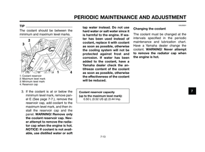
1. Air filter element
ECA10480
NOTICE
●Make sure that the air filter ele-
ment is properly seated in the
air filter case.
●The engine should never be op-
erated without the air filter ele-
ment installed, otherwise the
piston(s) and/or cylinder(s) may
become excessively worn.
5. Install the air filter case cover by
installing the screws.
6. Install the seat.
1
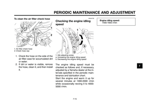
EAUB1480
Replacing the air filter
element and cleaning the
check hose
The air filter element should be re-
placed at the intervals specified in the
periodic maintenance and lubrication
chart. Replace the air filter element
more frequently if you are riding in un-
usually wet or dusty areas. In addition,
the air filter check hose must be fre-
quently checked and cleaned if neces-
sary. To replace the air filter element
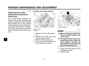
1. Air filter case
2. Screws
1. Remove the seat. (See page 4-
14.)
2. Remove the air filter case cover
by removing the screws.
3. Pull the air filter element out.
4. Insert a new air filter element into
the air filter case as shown.
XT660Z 05-07 ING-AUS:MY03 04-06 ING 11-05-2009 10:09 Pagina 7-14