Page 17 of 100

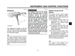
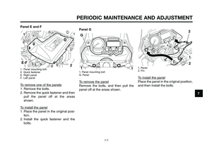
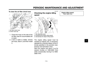
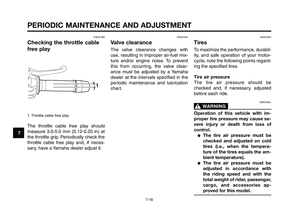
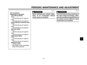
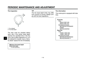
2. Standard keys (black bow)
This vehicle is equipped with an im-
mobilizer s")
1
2
3
4
5
6
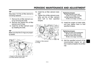
7
8
9
10
4-1
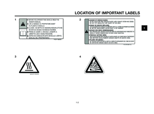
INSTRUMENT AND CONTROL FUNCTIONS
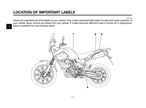
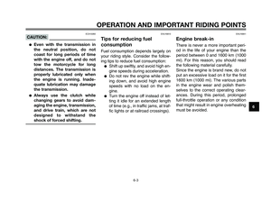
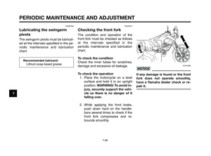
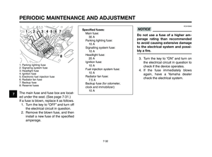
EAU10976
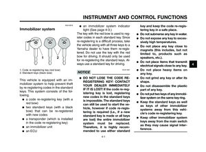
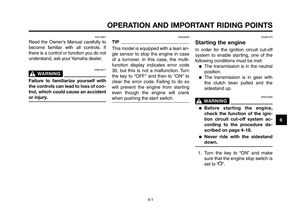
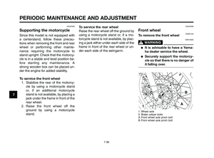
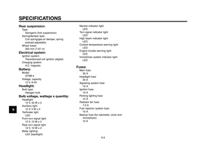
Immobilizer system
1. Code re-registering key (red bow)
2. Standard keys (black bow)
This vehicle is equipped with an im-
mobilizer system to help prevent theft
by re-registering codes in the standard
keys. This system consists of the fol-
lowing.
●a code re-registering key (with a
red bow)
●two standard keys (with a black
bow) that can be re-registered
with new codes
●a transponder (which is installed
in the code re-registering key)
●an immobilizer unit
●an ECU
●an immobilizer system indicator
light (See page 4-3.)
The key with the red bow is used to reg-
ister codes in each standard key. Since
re-registering is a difficult process, take
the vehicle along with all three keys to a
Yamaha dealer to have them re-regis-
tered. Do not use the key with the red
bow for driving. It should only be used
for re-registering the standard keys. Al-
ways use a standard key for driving.
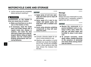
ECA11821NOTICE
●DO NOT LOSE THE CODE RE-
REGISTERING KEY! CONTACT
YOUR DEALER IMMEDIATELY
IF IT IS LOST! If the code re-reg-
istering key is lost, registering
new codes in the standard keys
is impossible. The standard keys
can still be used to start the ve-
hicle, however if code re-regis-
tering is required (i.e., if a new
standard key is made or all keys
are lost) the entire immobilizer
system must be replaced.
Therefore, it is highly recom-
mended to use either standardkey and keep the code re-regis-
tering key in a safe place.
●Do not submerse any key in water.
●Do not expose any key to exces-
sively high temperatures.
●Do not place any key close to
magnets (this includes, but not
limited to, products such as
speakers, etc.).
●Do not place items that transmit
electrical signals close to any key.
●Do not place heavy items on
any key.
●Do not grind any key or alter its
shape.
●Do not disassemble the plastic
part of any key.
●Do not put two keys of any immobi-
lizer system on the same key ring.
●Keep the standard keys as well
as keys of other immobilizer
systems away from this vehi-
cle's code re-registering key.
●Keep other immobilizer system
keys away from the main switch
as they may cause signal inter-
ference.
XT660Z 04-04 ING-AUS:MY03 01-03 ING 11-05-2009 9:54 Pagina 4-1
Page 18 of 100

INSTRUMENT AND CONTROL FUNCTIONS
4-2
1
2
3
4
5
6
7
8
9
10
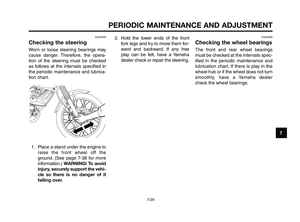
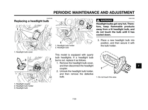
EAU10471
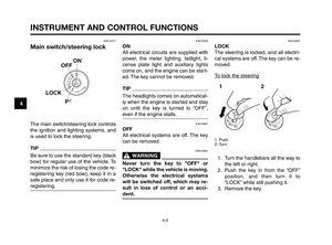
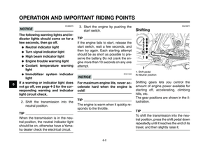
Main switch/steering lock
The main switch/steering lock controls
the ignition and lighting systems, and
is used to lock the steering.
TIP
Be sure to use the standard key (black
bow) for regular use of the vehicle. To
minimize the risk of losing the code re-
registering key (red bow), keep it in a
safe place and only use it for code re-
registering.
EAU10550
ON
All electrical circuits are supplied with
power, the meter lighting, taillight, li-
cense plate light and auxiliary lights
come on, and the engine can be start-
ed. The key cannot be removed.
TIP
The headlights comes on automatical-
ly when the engine is started and stay
on until the key is turned to “OFF”,
even if the engine stalls.
EAU10661
OFF
All electrical systems are off. The key
can be removed.
EWA10061
WARNING0
Never turn the key to "OFF" or
"LOCK" while the vehicle is moving.
Otherwise the electrical systems
will be switched off, which may re-
sult in loss of control or an acci-
dent.
EAU10691
LOCK
The steering is locked, and all electri-
cal systems are off. The key can be re-
moved.
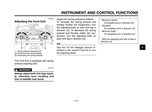
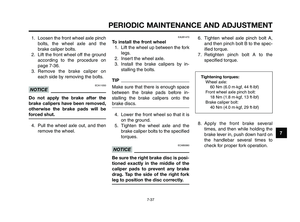
To lock the steering
1. Push
2. Turn
1. Turn the handlebars all the way to
the left or right.
2. Push the key in from the “OFF”
position, and then turn it to
“LOCK” while still pushing it.
3. Remove the key.
XT660Z 04-04 ING-AUS:MY03 01-03 ING 11-05-2009 9:54 Pagina 4-2
Page 19 of 100

1
2
3
4
5
6
7
8
9
10
INSTRUMENT AND CONTROL FUNCTIONS
4-3
To unlock the steering
1. Push
2. Turn
Push the key into the main switch, and
then turn it to “OFF” while still pushing
it.
EAU10941
F(Parking)
The steering is locked, and the tail-
light, license plate light and auxiliary
lights are on. The hazard lights and
turn signal lights can be turned on, but
all other electrical systems are off. The
key can be removed.
The steering must be locked before
the key can be turned to “F”.
ECA11020NOTICE
Do not use the parking position for
an extended length of time, other-
wise the battery may discharge.
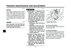
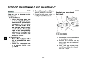
EAU11004
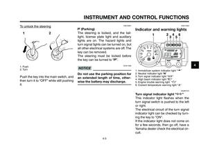
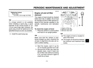
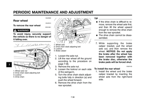
Indicator and warning lights
1. Immobilizer system indicator light “ ”
2. Neutral indicator light “N”
3. Turn signal indicator light “y”
4. High beam indicator light “1”
5. Engine trouble warning light “U”
6. Coolant temperature warning light “u”
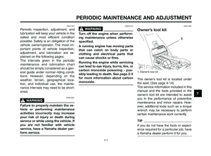
EAUB1510
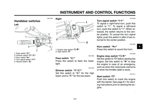
Turn signal indicator light “y”
This indicator light flashes when the
turn signal switch is pushed to the left
or right.
The electrical circuit of the turn signal
indicator light can be checked by turn-
ing the key to "ON".
If the indicator light does not come on
for a few seconds, then go off, have a
Yamaha dealer check the electrical cir-
cuit.
XT660Z 04-04 ING-AUS:MY03 01-03 ING 11-05-2009 9:54 Pagina 4-3
Page 20 of 100

INSTRUMENT AND CONTROL FUNCTIONS
4-4
1
2
3
4
5
6
7
8
9
10
EAUB1520
Neutral indicator light “ N”
This indicator light comes on when the
transmission is in the neutral position.
The electrical circuit of the neutral indi-
cator light can be checked by turning
the key to "ON". If the indicator light
does not come on for a few seconds,
then go off, have a Yamaha dealer
check the electrical circuit.
EAUB1530
High beam indicator light “1”
This indicator light comes on when the
high beam of the headlight is switched
on. The electrical circuit of the high
beam indicator light can be checked
by turning the key to "ON". If the indi-
cator light does not come on for a few
seconds, then go off, have a Yamaha
dealer check the electrical circuit.
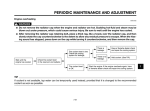
EAU11444
Coolant temperature warning
light “u”
This warning light comes on if the en-
gine overheats. If this occurs, stop the
engine immediately and allow the en-
gine to cool. The electrical circuit of the
warning light can be checked by turn-
ing the key to "ON". The warning light
should come on for a few seconds,and then go off. If the warning light
does not come on initially when the
key is turned to "ON", or if the warning
light remains on, have a Yamaha deal-
er check the electrical circuit.
ECA10021
NOTICE
Do not continue to operate the en-
gine if it is overheating.
TIP
●For radiator-fan-equipped vehi-
cles, the radiator fan(s) automati-
cally switch on or off according to
the coolant temperature in the ra-
diator.
●If the engine overheats, see page
7-41 for further instructions.
EAU11534
Engine trouble warning light “U”
This warning light comes on or flashes
if a problem is detected in the electri-
cal circuit monitoring the engine. If this
occurs, have a Yamaha dealer check
the self-diagnosis system. (See page
4-8 for an explanation of the self-diag-
nosis device.) The electrical circuit of
the warning light can be checked byturning the key to "ON". The warning
light should come on for a few seconds,
and then go off. If the warning light does
not come on initially when the key is
turned to "ON", or if the warning light re-
mains on, have a Yamaha dealer check
the electrical circuit.
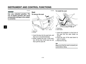
EAU26876
Immobilizer system indicator
light “ ”
The electrical circuit of the indicator
light can be checked by turning the
key to "ON". The indicator light should
come on for a few seconds, and then
go off. If the indicator light does not
come on initially when the key is
turned to "ON", or if the indicator light
remains on, have a Yamaha dealer
check the electrical circuit.
When the key is turned to "OFF" and
30 seconds have passed, the indicator
light will start flashing indicating the
immobilizer system is enabled. After
24 hours have passed, the indicator
light will stop flashing, however the im-
mobilizer system is still enabled.
This model is also equipped with a
self-diagnosis device for the immobi-
lizer system. (See page 4-8 for an ex-
planation of the self-diagnosis device.)
XT660Z 04-04 ING-AUS:MY03 01-03 ING 11-05-2009 9:54 Pagina 4-4
Page 21 of 100

1
2
3
4
5
6
7
8
9
10
INSTRUMENT AND CONTROL FUNCTIONS
4-5
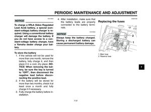
EAUB1501
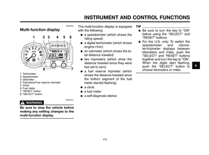
Multi-function display
1. Tachometer
2. Speedometer
3. Odometer
4. Tripmeters/Fuel reserve tripmeter
5. Clock
6. Fuel meter
7. “RESET” button
8. “SELECT” button
EWA12311
WARNING0
Be sure to stop the vehicle before
making any setting changes to the
multi-function display.
The multi-function display is equipped
with the following:
●a speedometer (which shows the
riding speed)
●a digital tachometer (which shows
engine r/min)
●an odometer (which shows the to-
tal distance traveled)
●two tripmeters (which show the
distance traveled since they were
last set to zero)
●a fuel reserve tripmeter (which
shows the distance traveled since
the bottom segment of the fuel
meter started flashing)
●a clock
●a fuel meter
●a self-diagnosis device
TIP
●Be sure to turn the key to "ON"
before using the "SELECT" and
"RESET" buttons.
●For the U.K. only: To switch the
speedometer and odome-
ter/tripmeter displays between
kilometers and miles, push the
"SELECT" and "RESET" buttons
together and turn the key to "ON".
When the digits start flashing,
push the "SELECT" button to
choose kilometers or miles.
XT660Z 04-04 ING-AUS:MY03 01-03 ING 11-05-2009 9:54 Pagina 4-5
Page 22 of 100

INSTRUMENT AND CONTROL FUNCTIONS
4-6
1
2
3
4
5
6
7
8
9
10
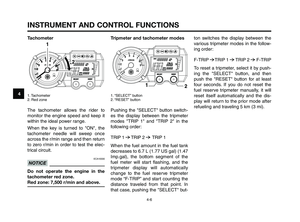
Tachometer
1. Tachometer
2. Red zone
The tachometer allows the rider to
monitor the engine speed and keep it
within the ideal power range.
When the key is turned to "ON", the
tachometer needle will sweep once
across the r/min range and then return
to zero r/min in order to test the elec-
trical circuit.
ECA10030
NOTICE
Do not operate the engine in the
tachometer red zone.
Red zone: 7,500 r/min and above.
Tripmeter and tachometer modes
1. “SELECT” button
2. “RESET” button
Pushing the "SELECT" button switch-
es the display between the tripmeter
modes "TRIP 1" and "TRIP 2" in the
following order:
TRIP 1
6TRIP 2 6TRIP 1
When the fuel amount in the fuel tank
decreases to 6.7 L (1.77 US gal) (1.47
Imp.gal), the bottom segment of the
fuel meter will start flashing, and the
tripmeter display will automatically
change to the fuel reserve tripmeter
mode “F-TRIP” and start counting the
distance traveled from that point. In
that case, pushing the "SELECT" but-
ton switches the display between the
various tripmeter modes in the follow-
ing order:
F-TRIP
6TRIP 1 6TRIP 2 6F-TRIP
To reset a tripmeter, select it by push-
ing the "SELECT" button, and then
push the "RESET" button for at least
four seconds. If you do not reset the
fuel reserve tripmeter manually, it will
reset itself automatically and the dis-
play will return to the prior mode after
refueling and traveling 5 km (3 mi).
XT660Z 04-04 ING-AUS:MY03 01-03 ING 11-05-2009 9:54 Pagina 4-6
Page 23 of 100

1
2
3
4
5
6
7
8
9
10
INSTRUMENT AND CONTROL FUNCTIONS
4-7
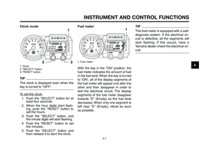
Clock mode
1. Clock
2. “SELECT” button
3. “RESET” button
TIP
The clock is displayed even when the
key is turned to "OFF".
To set the clock:
1. Push the "SELECT" button for at
least four seconds.
2. When the hour digits start flash-
ing, push the "RESET" button to
set the hours.
3. Push the "SELECT" button, and
the minute digits will start flashing.
4. Push the "RESET" button to set
the minutes.
5. Push the "SELECT" button and
then release it to start the clock.
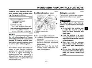
Fuel meter
1. Fuel meter
With the key in the "ON" position, the
fuel meter indicates the amount of fuel
in the fuel tank. When the key is turned
to "ON", all of the display segments of
the fuel meter will appear one after the
other and then disappear in order to
test the electrical circuit. The display
segments of the fuel meter disappear
towards "E" (Empty) as the fuel level
decreases. When only one segment is
left near "E" (Empty), refuel as soon
as possible.
TIP
This fuel meter is equipped with a self-
diagnosis system. If the electrical cir-
cuit is defective, all the segments will
start flashing. If this occurs, have a
Yamaha dealer check the electrical cir-
cuit.
XT660Z 04-04 ING-AUS:MY03 01-03 ING 11-05-2009 9:54 Pagina 4-7
Page 24 of 100

INSTRUMENT AND CONTROL FUNCTIONS
4-8
1
2
3
4
5
6
7
8
9
10
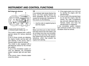
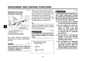
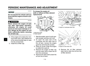
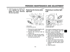
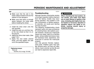
Self-diagnosis devices
1. Engine trouble warning light “U”
2. Immobilizer system indicator light “ ”
This model is equipped with a self-di-
agnosis device for various electrical
circuits.
If any of those circuits are defective,
the engine trouble warning light will
start flashing. If this occurs, have a
Yamaha dealer check the vehicle.
This model is also equipped with a
self-diagnosis device for the immobi-
lizer system.
If any of the immobilizer system cir-
cuits are defective, the immobilizer
system indicator light will start flash-
ing.
If this occurs, have a Yamaha dealer
check the vehicle.
TIP
If the indicator light slowly flashes five
times, and then quickly flashes two
times repeatedly, this error could be
caused by transponder interference. If
this occurs, try the following.
1. Use the code re-registering key to
start the engine.
TIP
Make sure there are no other immobi-
lizer keys close to the main switch, and
do not keep more than one immobiliz-
er key on the same key ring! Immobi-
lizer system keys may cause signal in-
terference, which may prevent the
engine from starting.2. If the engine starts, turn it off, and
try starting the engine with the
standard keys.
3. If one or both of the standard keys
do not start the engine, take the
vehicle, the code re-registering
key and both standard keys to a
Yamaha dealer and have the
standard keys re-registered.
If the immobilizer system indicator
light continues to flash, have a Yama-
ha dealer check the vehicle.
XT660Z 04-04 ING-AUS:MY03 01-03 ING 11-05-2009 9:54 Pagina 4-8