Page 25 of 100

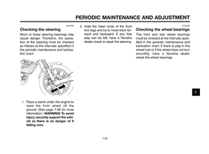
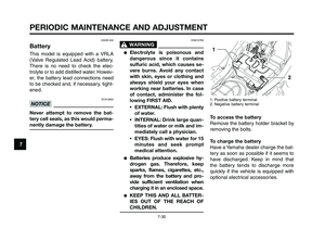
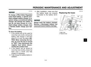
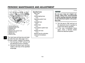
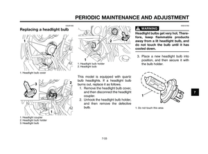
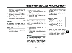
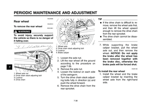
1
2
3
4
5
6
7
8
9
10
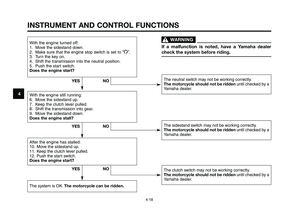
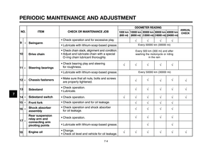
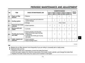
INSTRUMENT AND CONTROL FUNCTIONS
4-9
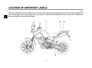
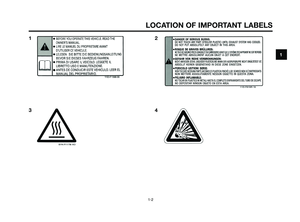
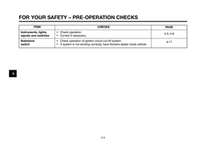
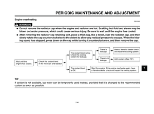
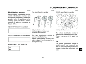
EAU12348
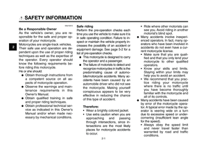
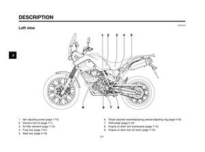
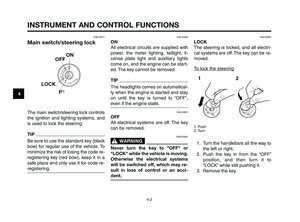
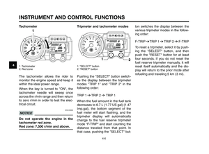
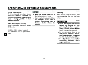
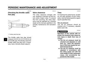
Handlebar switches
Left
1. Pass switch “1”
2. Dimmer switch “2/ 1”
3. Horn switch “o”
4. Turn signal switch “y”
5. Hazard switch “
r”
54
2
1
3
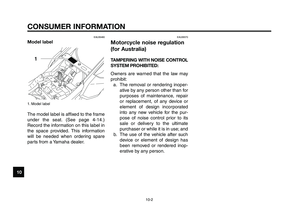
Right
1. Engine stop switch “I/”
2. Start switch “J”
EAU12350
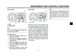
Pass switch “1”
Press this switch to flash the head-
light.
EAU12400
Dimmer switch “2/1”
Set this switch to “
1” for the high
beam and to “2” for the low beam.
B
EAU12460
Turn signal switch “y”
To signal a right-hand turn, push this
switch to “Δ”. To signal a left-hand
turn, push this switch to “Ÿ”. When re-
leased, the switch returns to the cen-
ter position. To cancel the turn signal
lights, push the switch in after it has re-
turned to the center position.
EAU12500
Horn switch “o”
Press this switch to sound the horn.
EAU12660
Engine stop switch “I/”
Set this switch to “I” before starting the
engine. Set this switch to “ ” to stop
the engine in case of an emergency,
such as when the motorcycle overturns
or when the throttle cable is stuck.
EAU12711
Start switch “J”
Push this switch to crank the engine
with the starter. See page 6-1 for start-
ing instructions prior to starting the en-
gine.
,
B
B
XT660Z 04-04 ING-AUS:MY03 01-03 ING 11-05-2009 9:54 Pagina 4-9
Page 26 of 100

INSTRUMENT AND CONTROL FUNCTIONS
4-10
1
2
3
4
5
6
7
8
9
10
EAU12733
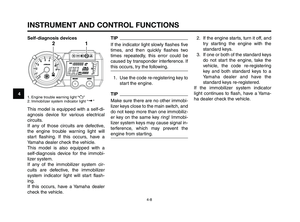
Hazard switch “r”
With the key in the “ON” or Fposition,
use this switch to turn on the hazard
lights (simultaneous flashing of all turn
signal lights).
The hazard lights are used in case of
an emergency or to warn other drivers
when your vehicle is stopped where it
might be a traffic hazard.
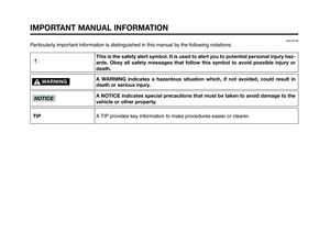
ECA10061
NOTICE
Do not use the hazard lights for an
extended length of time with the
engine not running, otherwise the
battery may discharge.
EAU12820
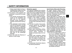
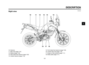
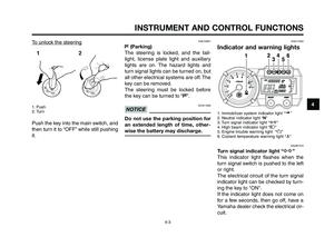
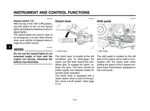
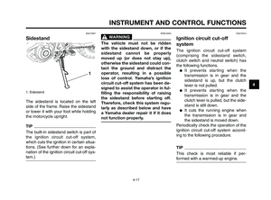
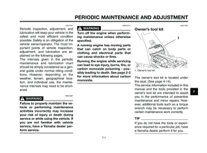
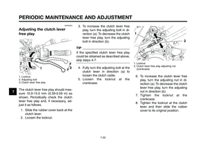
Clutch lever
1. Clutch lever
The clutch lever is located at the left
handlebar grip. To disengage the
clutch, pull the lever toward the han-
dlebar grip. To engage the clutch, re-
lease the lever. The lever should be
pulled rapidly and released slowly for
smooth clutch operation.
The clutch lever is equipped with a
clutch switch, which is part of the igni-
tion circuit cut-off system. (See page
4-17).
1
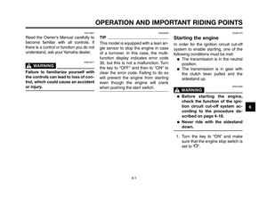
EAU12870
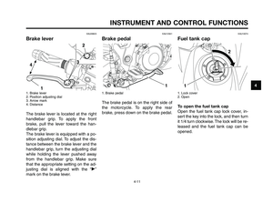
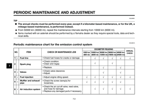
Shift pedal
1. Shift pedal
The shift pedal is located on the left
side of the engine and is used in com-
bination with the clutch lever when
shifting the gears of the 5-speed con-
stant-mesh transmission equipped on
this motorcycle.
XT660Z 04-04 ING-AUS:MY03 01-03 ING 11-05-2009 9:54 Pagina 4-10
Page 27 of 100

1
2
3
4
5
6
7
8
9
10
INSTRUMENT AND CONTROL FUNCTIONS
4-11
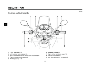
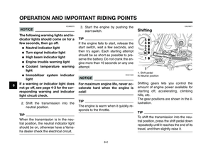
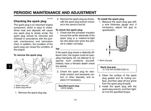
EAU26823
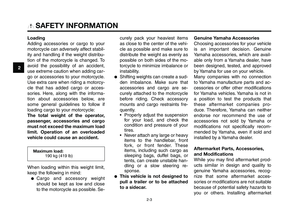
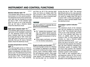
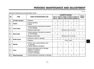
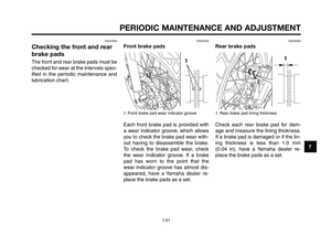
Brake lever
1. Brake lever
2. Position adjusting dial
3. Arrow mark
4. Distance
The brake lever is located at the right
handlebar grip. To apply the front
brake, pull the lever toward the han-
dlebar grip.
The brake lever is equipped with a po-
sition adjusting dial. To adjust the dis-
tance between the brake lever and the
handlebar grip, turn the adjusting dial
while holding the lever pushed away
from the handlebar grip. Make sure
that the appropriate setting on the ad-
justing dial is aligned with the “˙”
mark on the brake lever.
EAU12941
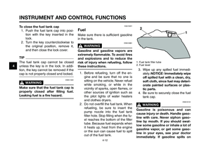
Brake pedal
1. Brake pedal
The brake pedal is on the right side of
the motorcycle. To apply the rear
brake, press down on the brake pedal.
1
EAU13074
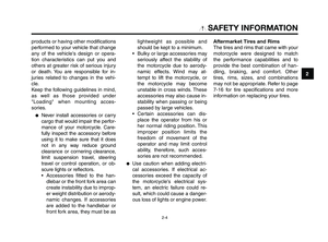
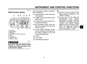
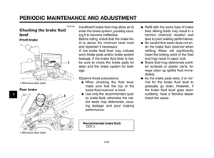
Fuel tank cap
1. Lock cover
2. Open
To open the fuel tank cap
Open the fuel tank cap lock cover, in-
sert the key into the lock, and then turn
it 1/4 turn clockwise. The lock will be re-
leased and the fuel tank cap can be
opened.
XT660Z 04-04 ING-AUS:MY03 01-03 ING 11-05-2009 9:54 Pagina 4-11
Page 28 of 100

INSTRUMENT AND CONTROL FUNCTIONS
4-12
1
2
3
4
5
6
7
8
9
10
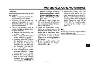
To close the fuel tank cap
1. Push the fuel tank cap into posi-
tion with the key inserted in the
lock.
2. Turn the key counterclockwise to
the original position, remove it,
and then close the lock cover.
TIP
The fuel tank cap cannot be closed
unless the key is in the lock. In addi-
tion, the key cannot be removed if the
cap is not properly closed and locked.
EWA11091
WARNING0
Make sure that the fuel tank cap is
properly closed after filling fuel.
Leaking fuel is a fire hazard.
EAU13221
Fuel
Make sure there is sufficient gasoline
in the tank.
EWA10881
WARNING0
Gasoline and gasoline vapors are
extremely flammable. To avoid fires
and explosions and to reduce the
risk of injury when refueling, follow
these instructions.
1. Before refueling, turn off the en-
gine and be sure that no one is
sitting on the vehicle. Never refuel
while smoking, or while in the
vicinity of sparks, open flames, or
other sources of ignition such as
the pilot lights of water heaters
and clothes dryers.
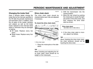
2. Do not overfill the fuel tank. When
refueling, be sure to insert the
pump nozzle into the fuel tank
filler hole. Stop filling when the fu-
el reaches the bottom of the filler
tube. Because fuel expands when
it heats up, heat from the engine
or the sun can cause fuel to spill
out of the fuel tank.
1. Fuel tank filler tube
2. Fuel level
3. Wipe up any spilled fuel immedi-
ately. NOTICE:Immediately wipe
off spilled fuel with a clean, dry,
soft cloth, since fuel may deteri-
orate painted surfaces or plas-
tic parts.
4. Be sure to securely close the fuel
tank cap.
EWA15151
WARNING0
Gasoline is poisonous and can
cause injury or death. Handle gaso-
line with care. Never siphon gaso-
line by mouth. If you should swal-
low some gasoline or inhale a lot of
gasoline vapor, or get some gaso-
line in your eyes, see your doctor
immediately. If gasoline spills on
XT660Z 04-04 ING-AUS:MY03 01-03 ING 11-05-2009 9:54 Pagina 4-12
Page 29 of 100

1
2
3
4
5
6
7
8
9
10
INSTRUMENT AND CONTROL FUNCTIONS
4-13
your skin, wash with soap and wa-
ter. If gasoline spills on your cloth-
ing, change your clothes.
EAU13390EAU13412
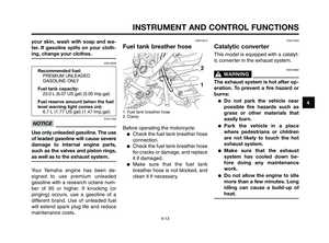
Fuel tank breather hose
1. Fuel tank breather hose
2. Clamp
Before operating the motorcycle:
●Check the fuel tank breather hose
connection.
●Check the fuel tank breather hose
for cracks or damage, and replace
it if damaged.
●Make sure that the fuel tank
breather hose is not blocked, and
clean it if necessary.
ECA11400
NOTICE
Use only unleaded gasoline. The use
of leaded gasoline will cause severe
damage to internal engine parts,
such as the valves and piston rings,
as well as to the exhaust system.
Your Yamaha engine has been de-
signed to use premium unleaded
gasoline with a research octane num-
ber of 95 or higher. If knocking (or
pinging) occurs, use a gasoline of a
different brand. Use of unleaded fuel
will extend spark plug life and reduce
maintenance costs.
Recommended fuel:
PREMIUM UNLEADED
GASOLINE ONLY
Fuel tank capacity:
23.0 L (6.07 US gal) (5.05 Imp.gal)
Fuel reserve amount (when the fuel
level warning light comes on):
6.7 L (1.77 US gal) (1.47 Imp.gal)
EAU13433
Catalytic converter
This model is equipped with a catalyt-
ic converter in the exhaust system.
EWA10862
WARNING0
The exhaust system is hot after op-
eration. To prevent a fire hazard or
burns:
●Do not park the vehicle near
possible fire hazards such as
grass or other materials that
easily burn.
●Park the vehicle in a place
where pedestrians or children
are not likely to touch the hot
exhaust system.
●Make sure that the exhaust
system has cooled down be-
fore doing any maintenance
work.
●Do not allow the engine to idle
more than a few minutes. Long
idling can cause a build-up of
heat.
XT660Z 04-04 ING-AUS:MY03 01-03 ING 11-05-2009 9:54 Pagina 4-13
Page 30 of 100
INSTRUMENT AND CONTROL FUNCTIONS
4-14
1
2
3
4
5
6
7
8
9
10
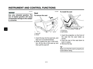
To install the seat
1. Projections
2. Seat holders
1. Insert the projection on the front of
the seat into the seat holder as
shown.
2. Push the rear of the seat down to
lock it in place.
3. Remove the key.
TIP
Make sure that the seat is properly se-
cured before riding.
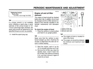
EAU32980
Seat
To remove the seat
1. Seat lock
2. Unlock
1. Insert the key into the seat lock, and
then turn it counterclockwise.
2. While holding the key in that posi-
tion, lift the rear of the seat up, and
then pull the seat off.
ECA10701
NOTICE
Use only unleaded gasoline. The
use of leaded gasoline will cause
unrepairable damage to the catalyt-
ic converter.
XT660Z 04-04 ING-AUS:MY03 01-03 ING 11-05-2009 9:54 Pagina 4-14
Page 31 of 100
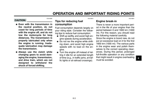
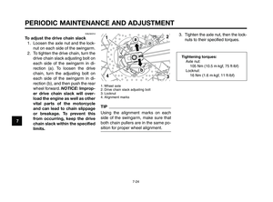
 Increasing the spring preload
(b) Decreasing the spring preload
This f")
1
2
3
4
5
6
7
8
9
10
INSTRUMENT AND CONTROL FUNCTIONS
4-15
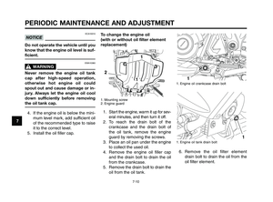
EAUB1550
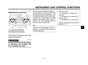
Adjusting the front fork
1. Spring preload adjusting bolt
(a) Increasing the spring preload
(b) Decreasing the spring preload
This front fork is equipped with spring
preload adjusting bolt.
EWA10180
WARNING0
Always adjust both fork legs equal-
ly, otherwise poor handling and
loss of stability may result.
Adjust the spring preload as follows.
To increase the spring preload and
thereby harden the suspension, turn
the adjusting bolts on each fork leg in
direction (a). To decrease the spring
preload and thereby soften the sus-
pension, turn the adjusting bolts on
each fork leg in direction (b).Maximum (hard):
0 complete turns in direction (b)*
Standard:
22 complete turns in direction (b)*
Minimum (soft):
27 complete turns in direction (b)*
* With the adjusting bolt fully turned in
direction (a)
TIP
Use the 10 mm hexagon wrench in-
cluded in the owner’s tool kit to turn
the adjusting bolts.
XT660Z 04-04 ING-AUS:MY03 01-03 ING 11-05-2009 9:54 Pagina 4-15
Page 32 of 100

INSTRUMENT AND CONTROL FUNCTIONS
4-16
1
2
3
4
5
6
7
8
9
10
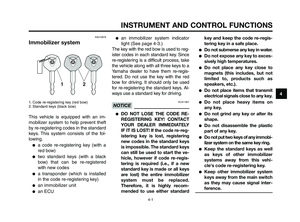
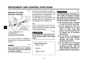
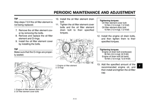
Adjust the spring preload as follows.
To increase the spring preload and
thereby harden the suspension, turn
the adjusting ring in direction (a).
To decrease the spring preload and
thereby soften the suspension, turn
the adjusting ring in direction (b).
TIP
Align the appropriate notch in the ad-
justing ring with the position indicator
on the shock absorber.
EWAB0020
WARNING0
Never adjust the spring preload un-
til the exhaust system has cooled
down.
EWA10221
WARNING0
This shock absorber assembly con-
tains highly pressurized nitrogen
gas. Read and understand the fol-
lowing information before handling
the shock absorber assembly.
●Do not tamper with or attempt
to open the cylinder assembly.
●Do not subject the shock ab-
sorber assembly to an open
flame or other high heat
source. This may cause the unit
to explode due to excessive
gas pressure.
●Do not deform or damage the
cylinder in any way. Cylinder
damage will result in poor
damping performance.
●Do not dispose of a damaged
or worn-out shock absorber
assembly yourself. Take the
shock absorber assembly to a
Yamaha dealer for any service.
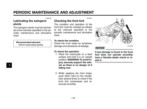
EAUB1461
Adjusting the shock
absorber assembly
1. Spring preload adjusting ring
2. Position indicator
(a) Increasing the spring preload
(b) Decreasing the spring preload
This shock absorber assembly is
equipped with a spring preload adjust-
ing ring.
ECA10100
NOTICE
Never attempt to turn an adjusting
mechanism beyond the maximum
or minimum settings.
Spring preload setting:
Minimum (soft):
1
Standard:
2
Maximum (hard):
9
XT660Z 04-04 ING-AUS:MY03 01-03 ING 11-05-2009 9:54 Pagina 4-16