2010 NISSAN TIIDA BCM
[x] Cancel search: BCMPage 602 of 3745

INTELLIGENT KEY SYSTEMBL-93
< SERVICE INFORMATION >
C
DE
F
G H
J
K L
M A
B
BL
N
O P
Even if Intelligent Key battery runs down, Intelligent key unit can start engine with mechanical key built Intelli-
gent Key. For details, refer toBL-248
.
All of the originally supplied Intelligent Key IDs (exc ept for key) have been registered in Intelligent Key system.
If requested by the vehicle owner, a maximum of four Intelligent Key IDs can be registered into the Intelligent
Key system components.
List of Operation Related Parts
Parts marked with × are the parts related to operation.
WARNING CHIME/BUZZER/LAMPS FUNCTION
Operation Description
The following warning chime (combination meter), Intelligent Key warning buzzer (front door LH), Intelligent
Key warning buzzer (trunk)
*, warning lamps "KEY" and “P-SHIFT” (with CVT or A/T) or "LOCK" (with M/T) are
given to the user as warning informati on while using the intelligent key system.
• Ignition switch warning chime
• Ignition key warning chime
• OFF position warning chime
• Take away warning chime
• Door lock operation warning chime
• Intelligent key low battery warning
• P position warning (with CVT or A/T)
• LOCK position warning (with M/T) NOTE:
For key-in-ignition warning chime related concerns only, refer to DI-43
.
* :
Sedan
Operation Condition
Engine start functions
Intelligent Key
Key switch
Ignition knob switch
Inside key antenna
Intelligent Key unit
CAN communication system
BCM
Combination meter
IPDM E/R
NATS antenna amp.
Steering lock solenoid
Engine start function by the Intelligent Key ××××××××× ×
Engine start function by the mechanical key ×××× ×××
Operation ConditionWarning chime/buzzer Warning lamp
Chime
(combina-
tion meter) Buzzer(s) KEY
LOCK
(M/T) P-SHIFT
(CVT or A/T)
Ignition switch warning chime • Mechanical key is out of ignition switch
(Key switch is OFF)
• Ignition switch is in the ACC, OFF or LOCK position.
[ignition switch is pressed
(ignition knob switch is ON).]
• Driver door is open. activate — — — —
Ignition key warning chime
(When mechanical key is used) • Mechanical key is inserted in ignition
switch (key switch is ON).
• Ignition switch is in the ACC, OFF or
LOCK position.
• Driver door is open. activate — — — —
P position warning (CVT or A/T) When selector lever is in other than P po-
sition, ignition switch is turned from ON to
OFF. activate — — — Flash
Revision: January 20102010 Versa
Page 604 of 3745

INTELLIGENT KEY SYSTEMBL-95
< SERVICE INFORMATION >
C
DE
F
G H
J
K L
M A
B
BL
N
O P
CHANGE SETTINGS FUNCTION
The settings for each function c an be changed with the CONSULT-III.
Changing Settings Using CONSULT-III
The settings for the Intelligent Key system func tions can be changed using CONSULT-III (WORK SUPPORT).
Refer to BL-117, "
CONSULT-III Application Item".
NOTE:
Once a function setting is changed, it will remain effective even if the battery is disconnected.
INTELLIGENT KEY REGISTRATION
Intelligent Key-ID registration is performed using the CONSULT-III.
CAUTION:
• After a new Intelligent Key-ID is registered, be sure to check the function.
• When registering an additional Intelligent Key-ID , take any Intelligent Keys already registered and
Intelligent Keys for any other vehicles out of the vehicle before starting.
CONSULT-III can be used to check and delete Intelligent Key-IDs.
For further information, see the CONS ULT-III Operation Manual NATS.
STEERING LOCK SOLENOID REGISTRATION
Steering Lock Solenoid ID Registration
CAUTION:
• The method for registering a steering lock solenoid ID depends on the status of the steering lock
solenoid and Intelligent Key unit (new or old unit).
• After registration is completed, press ignition switch with an Intelligent Key in the vehicle so that it can be turned, and confirm that it cannot be turned even when ignition sw itch is pressed without an
Intelligent Key in the vehicle.
For further information, see the CONSULT-III Operation Manual NATS-IVIS/NVIS.
CAN Communication System DescriptionINFOID:0000000005396600
Refer to LAN-7.
Warning and alarm functions
Intelligent Key
Key switch
Ignition knob switch
Ignition switch ACC position input signal
Ignition switch ON position input signal
Door switch
Door request switch
Inside key antenna
Outside key antenna (Driver, Passenger)
Outside key antenna (rear bumper)
Intelligent Key warning buzzer(s)
Intelligent Key unit
CAN communication system
BCM
Warning lamp
Warning chime (combination meter)
Ignition switch warning chime × ××××× ×
Ignition key warning chime
(When mechanical key used) ×××
×××
OFF position warning chime For internal
××× ××××××
For external ×××× ×××××
Take away warning chime Right after door is
closed
××× × × ×××××
Any door is open ××× × × ××××
Take away from
window ××× × × ××××××
Door lock operation warning chime ×××××××××
Intelligent Key low battery warning ×××× ××
Revision: January 20102010 Versa
Page 620 of 3745
INTELLIGENT KEY SYSTEMBL-111
< SERVICE INFORMATION >
C
DE
F
G H
J
K L
M A
B
BL
N
O P
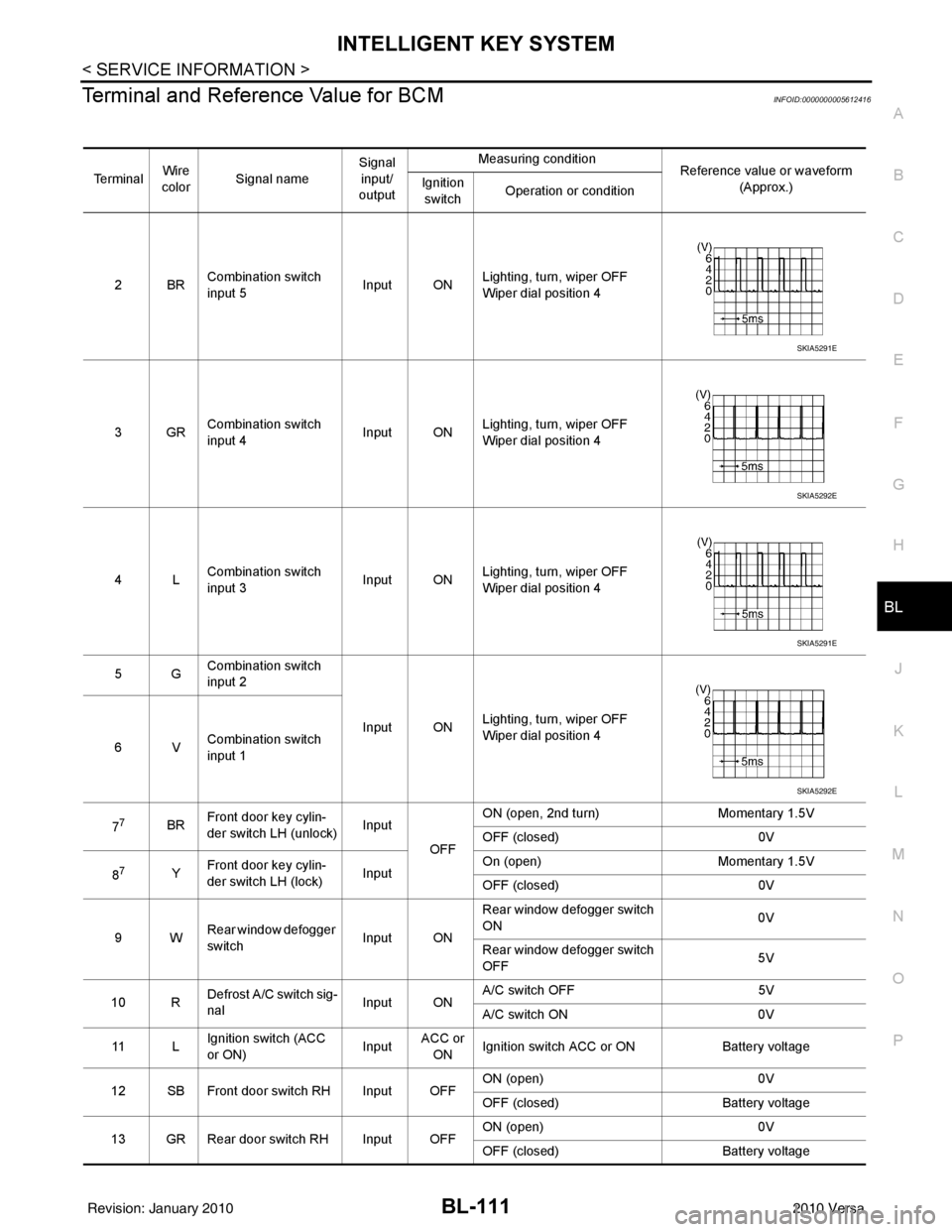
Terminal and Reference Value for BCMINFOID:0000000005612416
Te r m i n a l Wire
color Signal name Signal
input/
output Measuring condition
Reference value or waveform
(Approx.)
Ignition
switch Operation or condition
2BR Combination switch
input 5
Input ONLighting, turn, wiper OFF
Wiper dial position 4
3GR Combination switch
input 4 Input ONLighting, turn, wiper OFF
Wiper dial position 4
4L Combination switch
input 3
Input ONLighting, turn, wiper OFF
Wiper dial position 4
5G Combination switch
input 2
Input ONLighting, turn, wiper OFF
Wiper dial position 4
6V Combination switch
input 1
7
7BR Front door key cylin-
der switch LH (unlock) Input
OFFON (open, 2nd turn)
Momentary 1.5V
OFF (closed) 0V
8
7Y Front door key cylin-
der switch LH (lock) InputOn (open)
Momentary 1.5V
OFF (closed) 0V
9W Rear window defogger
switch Input ONRear window defogger switch
ON
0V
Rear window defogger switch
OFF 5V
10 R Defrost A/C switch sig-
nal
Input ONA/C switch OFF
5V
A/C switch ON 0V
11 L Ignition switch (ACC
or ON) InputACC or
ON Ignition switch ACC or ON
Battery voltage
12 SB Front door switch RH Input OFF ON (open)
0V
OFF (closed) Battery voltage
13 GR Rear door switch RH Input OFF ON (open)
0V
OFF (closed) Battery voltage
SKIA5291E
SKIA5292E
SKIA5291E
SKIA5292E
Revision: January 20102010 Versa
Page 624 of 3745

INTELLIGENT KEY SYSTEMBL-115
< SERVICE INFORMATION >
C
DE
F
G H
J
K L
M A
B
BL
N
O P
1: With Intelligent Key
2: Without Intelligent Key
3: Hatchback without Intelligent Key
4: Sedan without Intelligent Key
5: Hatchback
6: Sedan
7: With power door locks
8: With power windows
Trouble Diagnosis ProcedureINFOID:0000000005396608
PRELIMINARY CHECK
1.GET SYMPTOMS
Listen to customer c oncerns. (Get symptoms)
NOTE:
If customer reports a “No start” condition, request all Intelligent Keys to be brought to the dealer in case of
Intelligent Key system malfunction.
Intelligent Key or mechanical key service request>>For further information, refer to CONSULT-III operation
manual.
Malfunctions>>GO TO 2
2.CHECK BCM CONFIGURATION
Confirm BCM configuration for "I- KEY" is set to "WITH". Refer to BCS-19, "
Configuration".
OK or NG
OK >> GO TO 3
NG >> Change BCM configuration for "I-KEY" to "WITH". Refer to BCS-19, "
Configuration".
3.START ENGINE WITH INTELLIGENT KEY
Check if the engine could be started by all registered Intelligent Keys.
The engine cannot be started by some Intelligent Keys>>Int elligent Key is low battery or malfunction. Refer
to BL-158, "
Intelligent Key Battery Replacement".
The engine cannot be started by all Intelligent Keys >> GO TO 4
657SB All door lock actuators
(lock) Output OFFOFF (neutral)
0V
ON (lock) Battery voltage
66
7G Front door lock actua-
tor RH, rear door lock
actuators LH/RH (un-
lock) Output OFFOFF (neutral)
0V
ON (unlock) Battery voltage
67 B Ground Input ON—0V
68
8L Power window power
supply (RAP)
Output —Ignition switch ON
Battery voltage
Within 45 seconds after igni-
tion switch OFF Battery voltage
More than 45 seconds after ig-
nition switch OFF 0V
When front door LH or RH is
open or power window timer
operates 0V
69
8P Battery power supply OutputOFF
— Battery voltage
70 Y Battery power supply Input OFF —Battery voltage
Te r m i n a l
Wire
color Signal name Signal
input/
output Measuring condition
Reference value or waveform
(Approx.)
Ignition
switch Operation or condition
Revision: January 20102010 Versa
Page 627 of 3745
![NISSAN TIIDA 2010 Service Repair Manual BL-118
< SERVICE INFORMATION >
INTELLIGENT KEY SYSTEM
*: Select “SELECTION FROM MENU”.
ACTIVE TEST
* : Sedan
WORK SUPPORT
STOP LAMP SWIndicates [ON/OFF] condition of stop lamp switch.
P RANGE SW I](/manual-img/5/57397/w960_57397-626.png "NISSAN TIIDA 2010 Service Repair Manual BL-118
< SERVICE INFORMATION >
INTELLIGENT KEY SYSTEM
*: Select “SELECTION FROM MENU”.
ACTIVE TEST
* : Sedan
WORK SUPPORT
STOP LAMP SWIndicates [ON/OFF] condition of stop lamp switch.
P RANGE SW I")
BL-118
< SERVICE INFORMATION >
INTELLIGENT KEY SYSTEM
*: Select “SELECTION FROM MENU”.
ACTIVE TEST
* : Sedan
WORK SUPPORT
STOP LAMP SWIndicates [ON/OFF] condition of stop lamp switch.
P RANGE SW Indicates [ON/OFF] condition of shift lever park position.
BD OPEN SW Indicates [ON/OFF] condition of back door open switch.
DOOR LOCK SIG* Indicates [ON/OFF] condition of door lock signal from Intelligent Key button.
DOOR UNLOCK SIG* Indicates [ON/OFF] condition of door unlock signal from Intelligent Key button
KEYLESS PANIC* Indicates [ON/OFF] condition of panic signal from Intelligent Key button
DOOR SW DR* Indicates [OPEN/CLOSE] condition of front door sw
itch driver side from BCM via CAN communica-
tion line.
DOOR SW AS* Indicates [OPEN/CLOSE] condition of front door switch passenger side from BCM via CAN commu-
nication line.
DOOR SW RR* Indicates [OPEN/CLOSE] condition of rear door switch RH from BCM via CAN communication line.
DOOR SW RL* Indicates [OPEN/CLOSE] condition of rear door switch LH from BCM via CAN communication line.
VEHICLE SPEED* Indicates [km/h] condition of vehicle speed.
Monitor item
Content
Te s t i t e mD e s c r i p t i o n
DOOR LOCK/UNLOCK This test is able to check door lock/unlock operation.
• The all door lock actuators are unlocked when “ALL UNLK” on CONSULT-III screen is touched.
• The all door lock actuators are locked when “LOCK” on CONSULT-III screen is touched.
ANTENNA This test is able to check Intelligent Key antenna operation.
When the following conditions are met, hazard warning lamps flash.
• Inside key antenna (front console) detects Intelligent Key, when “ROOM ANT1” on CONSULT-
III screen is touched.
• Inside key antenna (instrument panel and rear floor) detects Intelligent Key, when “ROOM
ANT2” on CONSULT-III screen is touched.
• Outside key antenna (driver side) detects Intelligent Key, when “DR ANT” on CONSULT-III screen is touched.
• Outside key antenna (passenger side) detects Intelligent Key, when “AS ANT” on CONSULT-III screen is touched.
• Outside key antenna (rear bumper) detects Intelligent Key, when “BK DR ANT” on CONSULT-
III screen is touched.
OUTSIDE BUZZER This test is able to check Intelligent Key warning buzzer operation.
Intelligent Key warning buzzer sounds when “ON” on CONSULT-III screen is touched.
INSIDE BUZZER This test is able to check Intelligent Key warning chime (Instrument panel) operation.
• Take away warning chime sounds when “TAKE OUT” on CONSULT-III screen is touched.
• Ignition switch warning chime sounds when “KNOB” on CONSULT-III screen is touched.
• Ignition key warning chime sounds when “KEY” on CONSULT-III screen is touched.
INDICATOR This test is able to check warning lamp operation.
• “KEY” Warning lamp (Green) illuminates when “BLUE ON” on CONSULT-III screen is touched.
• “KEY” Warning lamp (Red) illuminates when
“RED ON” on CONSULT-III screen is touched.
• “LOCK” Warning lamp illuminates when “KNOB ON” on CONSULT-III screen is touched.
• “KEY” Warning lamp (Green) flashes when “BLUE IND” on CONSULT-III screen is touched.
• “KEY” Warning lamp (RED) flashes when “RED IND” on CONSULT-III screen is touched.
• “P-SHIFT” Warning lamp flashes when “KNOB IND” on CONSULT-III screen is touched.
Monitor item Description
CONFIRM KEY FOB ID It can be checked whether Intelligent Key ID code is registered or not in this mode.
TAKE OUT FROM WINDOW
WARN Take away warning chime (from window) mode can be changed to operate (ON) or not operate
(OFF) with this mode. The operation mode will be changed when “CHANGE SETT” on CONSULT-
III screen is touched.
Revision: January 20102010 Versa
Page 632 of 3745

INTELLIGENT KEY SYSTEMBL-123
< SERVICE INFORMATION >
C
DE
F
G H
J
K L
M A
B
BL
N
O P
HAZARD AND BUZZER REMINDER FUNCTION MALFUNCTION
NOTE:
• Before performing the diagnosis in the following table, check “Trouble Diagnosis Procedure”. Refer to BL-
115, "Trouble Diagnosis Procedure".
• Make sure that vehicle is under the condition shown in “Conditions of vehicle” before starting diagnosis, and
check each symptom.
• If the following “symptoms” are detected, check syst ems shown in the “Diagnosis/service procedure” column
in this order.
Conditions of Vehicle (Operating Conditions)
• Ignition switch is not depressed.
• All doors are closed.
Symptom Diagnosis/service procedure Reference
page
All of the remote keyless entry functions do
not operate. 1. Check Intelligent Key unit power supply and ground circuit.
BL-126
2. Check key switch (BCM input).BL-128
3. Check Intelligent Key battery.BL-158
4. Remote Keyless Entry function inspection.BL-158
5. Replace Intelligent Key unit.BL-158
Auto lock function does not operate.1. Check “AUTO RELOCK TIMER”
setting in “WORK SUPPORT”. BL-1172. Replace Intelligent Key unit. BL-158
Key reminder function does not operate.1. Check door switch (hatchback).
BL-131
2. Check door switch (sedan).BL-133
3. Check inside key antenna.BL-146
4. Check unlock sensor.BL-140
5. Check Intelligent Key battery.BL-158
6. Replace Intelligent Key unit.BL-158
Panic alarm function does not operate.1. Check “PANIC ALARM DELAY” setting in “WORK SUPPORT”.
BL-117
2. Check Intelligent Key battery inspection.BL-158
3. Check horn function.BL-157
4. Check headlamp function.BL-157
5. Check key switch.BL-127
6. Check ignition knob switch.BL-129
7. Replace Intelligent Key unit.BL-158
SymptomDiagnosis/service procedure Reference page
Hazard reminder does not operate by request
switch.
(Buzzer reminder operate). 1. Check “HAZARD ANSWER BACK” setting in “WORK
SUPPORT”. BL-117
2. Check hazard function with hazard switch.
BL-156
3. Replace Intelligent Key unit.BL-158
Buzzer reminder does
not operate by request
switch.
(Hazard reminder oper-
ates).Intelligent Key
warning buzzer
does not operate.1. Check “ANSER BACK WITH I-KEY LOCK” or “ANSER
BACK WITH I-KEY UNLOCK” setting in “WORK SUP-
PORT”. BL-117
2. Check Intelligent Ke
y warning buzzer(s). BL-142
3. Replace Intelligent Key unit. BL-158
Hazard reminder does not operate by Intelli-
gent Key (door lock/unlock button).
(Buzzer reminder operates properly).1. Check “HAZARD ANSWER BACK” setting in “WORK
SUPPORT”. BL-117
2. Check hazard function with hazard switch.
BL-156
3. Replace Intelligent Key.BL-158
Revision: January 20102010 Versa
Page 633 of 3745

BL-124
< SERVICE INFORMATION >
INTELLIGENT KEY SYSTEM
WARNING CHIME/BUZZER FUNCTION MALFUNCTION
NOTE:
• Before performing the diagnosis in the following table, check “Trouble Diagnosis Procedure”. Refer to BL-
115, "Trouble Diagnosis Procedure".
• Make sure that vehicle is under the condition shown in “Conditions of vehicle” before starting diagnosis, and
check each symptom.
• If the following “symptoms” are detected, check syst ems shown in the “Diagnosis/service procedure” column
in this order.
Conditions of Vehicle (Operating Conditions)
Warning chime/buzzer functions operating condition is extremely complicated, during operating confirmations,
reconfirm the list above twice in order to ensure proper operation.
Buzzer reminder does
not operate by Intelligent
Key (door lock/unlock
button).
(Hazard reminder oper-
ates). Intelligent Key
warning buzzer
does not operate.1. Check “HORN WITH KEYLESS LOCK” setting in “WORK
SUPPORT”. BL-117
2. Check Intelligent Key warning buzzer(s).
BL-142
3. Replace Intelligent Key unit.BL-158
SymptomDiagnosis/service procedure Reference page
Symptom Diagnosis/service procedureReference page
Ignition switch warning chime does not oper-
ate. 1. Check ignition knob switch.
BL-129
2. Check door switch (hatchback).BL-131
3. Check door switch (sedan).BL-133
4. Check key switch.BL-127
5. Check Intelligent Key warning chime.BL-156
6. Replace Intelligent Key unit.BL-158
Ignition key warning chime does not operate.
(When mechanical key used).1. Check key switch (Intelligent Key unit input).
BL-127
2. Check key switch (BCM input).BL-128
3. Check door switch (hatchback).BL-131
4. Check door switch (sedan).BL-133
5. Check Intelligent Key warning chime.BL-156
6. Replace Intelligent Key unit.BL-158
OFF position warning chime (For internal)
does not operate.1. Check ignition switch position.
BL-150
2. Check ignition knob switch.BL-129
3. Check key switch.BL-127
4. Check combination meter warning chime.BL-156
5. Replace Intelligent Key unit.BL-158
OFF position warning
chime/buzzer (for ex-
ternal) does not oper-
ate.Both Intelligent Key
warning chime and
buzzer do not oper-
ate.1. Check ignition switch position.
BL-150
2. Check ignition knob switch.BL-129
3. Check key switch.BL-127
4. Check Intelligent Key warning chime.BL-156
5. Check Intelligent Key warning buzzer(s).BL-142
6. Replace Intelligent Key unit.BL-158
Intelligent Key warn-
ing buzzer does not
operate.Check Intelligent Key warning buzzer(s).
BL-142
Revision: January 20102010 Versa
Page 637 of 3745
BL-128
< SERVICE INFORMATION >
INTELLIGENT KEY SYSTEM
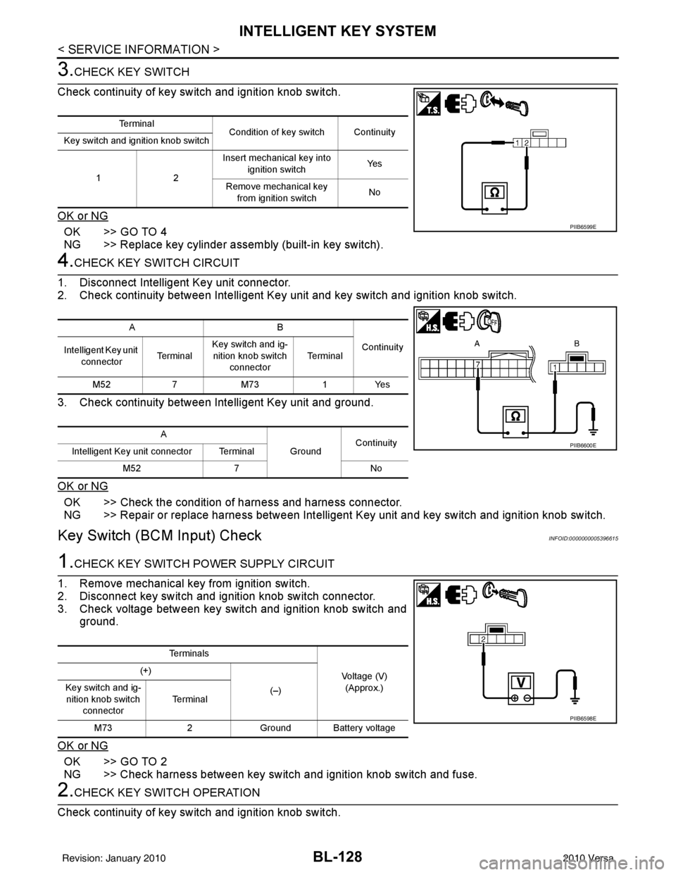
3.CHECK KEY SWITCH
Check continuity of key switch and ignition knob switch.
OK or NG
OK >> GO TO 4
NG >> Replace key cylinder assembly (built-in key switch).
4.CHECK KEY SWITCH CIRCUIT
1. Disconnect Intelligent Key unit connector.
2. Check continuity between Intelligent Key unit and key switch and ignition knob switch.
3. Check continuity between Intelligent Key unit and ground.
OK or NG
OK >> Check the condition of harness and harness connector.
NG >> Repair or replace harness between Intelligent Key unit and key switch and ignition knob switch.
Key Switch (BCM Input) CheckINFOID:0000000005396615
1.CHECK KEY SWITCH PO WER SUPPLY CIRCUIT
1. Remove mechanical key from ignition switch.
2. Disconnect key switch and ignition knob switch connector.
3. Check voltage between key switch and ignition knob switch and ground.
OK or NG
OK >> GO TO 2
NG >> Check harness between key switch and ignition knob switch and fuse.
2.CHECK KEY SWITCH OPERATION
Check continuity of key switch and ignition knob switch.
Te r m i n a l Condition of key switch Continuity
Key switch and ignition knob switch
12 Insert mechanical key into
ignition switch Ye s
Remove mechanical key from ignition switch No
PIIB6599E
AB
Continuity
Intelligent Key unit
connector Te r m i n a lKey switch and ig-
nition knob switch
connector Te r m i n a l
M52 7M73 1Yes
A GroundContinuity
Intelligent Key unit connector Terminal
M52 7 No
PIIB6600E
Te r m i n a l s
Voltage (V)(Approx.)
(+)
(–)
Key switch and ig-
nition knob switch
connector Te r m i n a l
M73 2Ground Battery voltage
PIIB6598E
Revision: January 20102010 Versa