Page 638 of 3745
INTELLIGENT KEY SYSTEMBL-129
< SERVICE INFORMATION >
C
DE
F
G H
J
K L
M A
B
BL
N
O P
OK or NG
OK >> GO TO 3
NG >> Replace key cylinder assembly (built-in key switch).
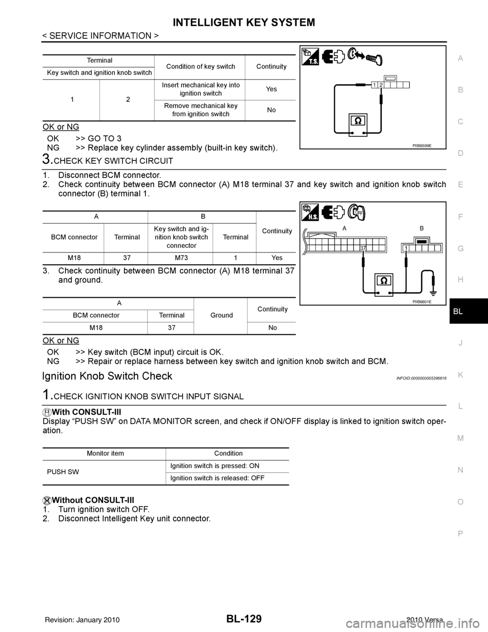
3.CHECK KEY SWITCH CIRCUIT
1. Disconnect BCM connector.
2. Check continuity between BCM connector (A) M18 terminal 37 and key switch and ignition knob switch
connector (B) terminal 1.
3. Check continuity between BCM connector (A) M18 terminal 37 and ground.
OK or NG
OK >> Key switch (BCM input) circuit is OK.
NG >> Repair or replace harness between key switch and ignition knob switch and BCM.
Ignition Knob Switch CheckINFOID:0000000005396616
1.CHECK IGNITION KNOB SWITCH INPUT SIGNAL
With CONSULT-III
Display “PUSH SW” on DATA MONITOR screen, and check if ON/OFF display is linked to ignition switch oper-
ation.
Without CONSULT-III
1. Turn ignition switch OFF.
2. Disconnect Intelligent Key unit connector.
Te r m i n a l Condition of key switch Continuity
Key switch and ignition knob switch
12 Insert mechanical key into
ignition switch Ye s
Remove mechanical key from ignition switch No
PIIB6599E
AB
Continuity
BCM connector Terminal Key switch and ig-
nition knob switch
connector Te r m i n a l
M18 37M73 1Yes
A GroundContinuity
BCM connector Terminal
M18 37 No
PIIB6601E
Monitor item Condition
PUSH SW Ignition switch is pressed: ON
Ignition switch is released: OFF
Revision: January 20102010 Versa
Page 640 of 3745
INTELLIGENT KEY SYSTEMBL-131
< SERVICE INFORMATION >
C
DE
F
G H
J
K L
M A
B
BL
N
O P
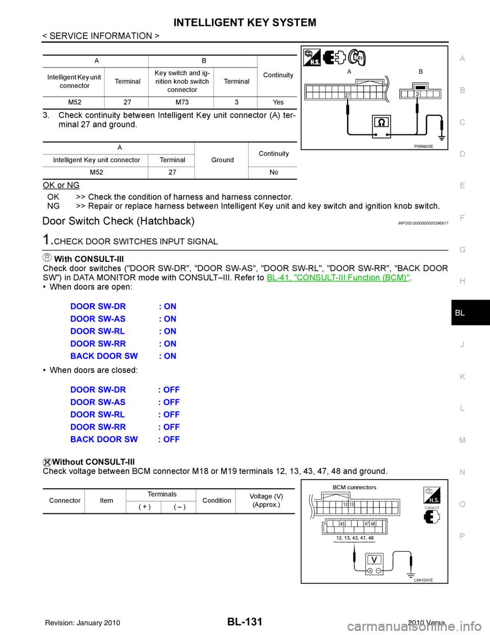
3. Check continuity between Intelligent Key unit connector (A) ter- minal 27 and ground.
OK or NG
OK >> Check the condition of harness and harness connector.
NG >> Repair or replace harness between Intelligent Key unit and key switch and ignition knob switch.
Door Switch Check (Hatchback)INFOID:0000000005396617
1.CHECK DOOR SWITCHES INPUT SIGNAL
With CONSULT-III
Check door switches ("DOOR SW-DR", "DOOR SW-AS", "DOOR SW-RL", "DOOR SW-RR", "BACK DOOR
SW") in DATA MONITOR mode with CONSULT–III. Refer to BL-41, "
CONSULT-III Function (BCM)".
• When doors are open:
• When doors are closed:
Without CONSULT-III
Check voltage between BCM connector M18 or M19 terminals 12, 13, 43, 47, 48 and ground.
AB
Continuity
Intelligent Key unit
connector Te r m i n a lKey switch and ig-
nition knob switch
connector Te r m i n a l
M52 27M73 3Yes
A GroundContinuity
Intelligent Key unit connector Terminal
M52 27 No
PIIB6605E
DOOR SW-DR : ON
DOOR SW-AS : ON
DOOR SW-RL : ON
DOOR SW-RR : ON
BACK DOOR SW : ON
DOOR SW-DR : OFF
DOOR SW-AS : OFF
DOOR SW-RL : OFF
DOOR SW-RR : OFF
BACK DOOR SW : OFF
Connector ItemTe r m i n a l s
ConditionVoltage (V)
(Approx.)
( + ) ( – )
LIIA1041E
Revision: January 20102010 Versa
Page 641 of 3745
BL-132
< SERVICE INFORMATION >
INTELLIGENT KEY SYSTEM
OK or NG
OK >> Door switch circuit is OK.
NG >> GO TO 2
2.CHECK DOOR SWITCH CIRCUIT
1. Turn ignition switch OFF.
2. Disconnect door switch and BCM.
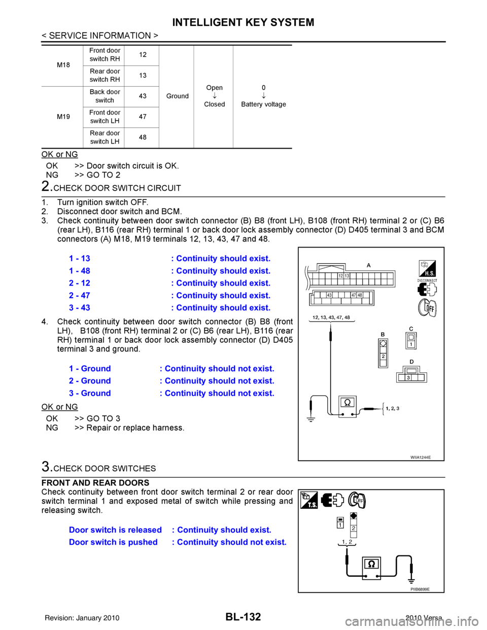
3. Check continuity between door switch connector (B) B8 (front LH), B108 (front RH) terminal 2 or (C) B6
(rear LH), B116 (rear RH) terminal 1 or back door lock assembly connector (D) D405 terminal 3 and BCM
connectors (A) M18, M19 terminals 12, 13, 43, 47 and 48.
4. Check continuity between door switch connector (B) B8 (front
LH), B108 (front RH) terminal 2 or (C) B6 (rear LH), B116 (rear
RH) terminal 1 or back door lock assembly connector (D) D405
terminal 3 and ground.
OK or NG
OK >> GO TO 3
NG >> Repair or replace harness.
3.CHECK DOOR SWITCHES
FRONT AND REAR DOORS
Check continuity between front door switch terminal 2 or rear door
switch terminal 1 and exposed metal of switch while pressing and
releasing switch.
M18 Front door
switch RH 12
Ground Open
↓
Closed 0
↓
Battery voltage
Rear door
switch RH 13
M19 Back door
switch 43
Front door switch LH 47
Rear door switch LH 48
1 - 13
: Continuity should exist.
1 - 48 : Continuity should exist.
2 - 12 : Continuity should exist.
2 - 47 : Continuity should exist.
3 - 43 : Continuity should exist.
1 - Ground : Continuity should not exist.
2 - Ground : Continuity should not exist.
3 - Ground : Continuity should not exist.
WIIA1244E
Door switch is released : Continuity should exist.
Door switch is pushed : Co ntinuity should not exist.
PIIB6899E
Revision: January 20102010 Versa
Page 642 of 3745
INTELLIGENT KEY SYSTEMBL-133
< SERVICE INFORMATION >
C
DE
F
G H
J
K L
M A
B
BL
N
O P
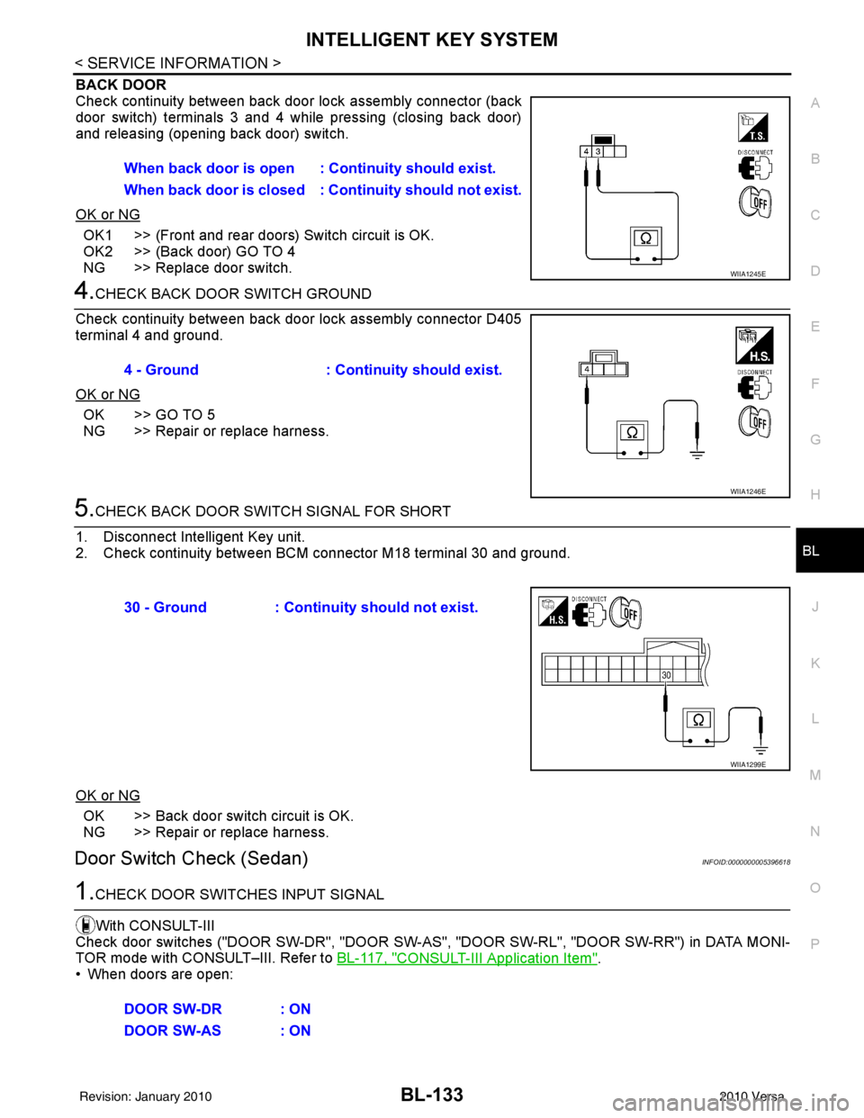
BACK DOOR
Check continuity between back door lock assembly connector (back
door switch) terminals 3 and 4 while pressing (closing back door)
and releasing (opening back door) switch.
OK or NG
OK1 >> (Front and rear doors) Switch circuit is OK.
OK2 >> (Back door) GO TO 4
NG >> Replace door switch.
4.CHECK BACK DOOR SWITCH GROUND
Check continuity between back door lock assembly connector D405
terminal 4 and ground.
OK or NG
OK >> GO TO 5
NG >> Repair or replace harness.
5.CHECK BACK DOOR SWITCH SIGNAL FOR SHORT
1. Disconnect Intelligent Key unit.
2. Check continuity between BCM connector M18 terminal 30 and ground.
OK or NG
OK >> Back door switch circuit is OK.
NG >> Repair or replace harness.
Door Switch Check (Sedan)INFOID:0000000005396618
1.CHECK DOOR SWITCHES INPUT SIGNAL
With CONSULT-III
Check door switches ("DOOR SW-DR", "DOOR SW-AS" , "DOOR SW-RL", "DOOR SW-RR") in DATA MONI-
TOR mode with CONSULT–III. Refer to BL-117, "
CONSULT-III Application Item".
• When doors are open: When back door is open : Continuity should exist.
When back door is closed : Continuity shou
ld not exist.
WIIA1245E
4 - Ground: Continuity should exist.
WIIA1246E
30 - Ground : Continuity should not exist.
WIIA1299E
DOOR SW-DR : ON
DOOR SW-AS : ON
Revision: January 20102010 Versa
Page 643 of 3745
BL-134
< SERVICE INFORMATION >
INTELLIGENT KEY SYSTEM
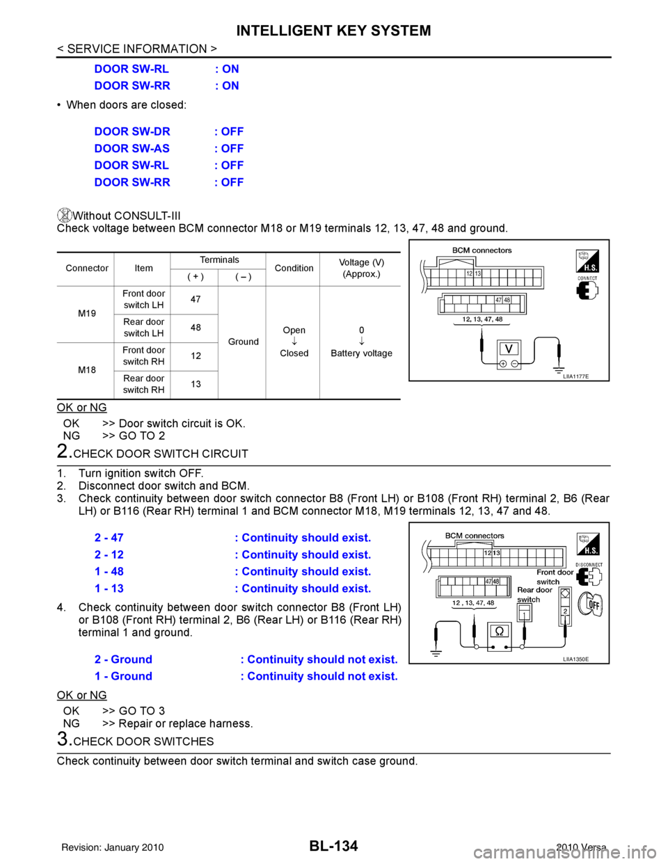
• When doors are closed:Without CONSULT-III
Check voltage between BCM connector M18 or M19 terminals 12, 13, 47, 48 and ground.
OK or NG
OK >> Door switch circuit is OK.
NG >> GO TO 2
2.CHECK DOOR SWITCH CIRCUIT
1. Turn ignition switch OFF.
2. Disconnect door switch and BCM.
3. Check continuity between door switch connector B8 (F ront LH) or B108 (Front RH) terminal 2, B6 (Rear
LH) or B116 (Rear RH) terminal 1 and BCM connector M18, M19 terminals 12, 13, 47 and 48.
4. Check continuity between door switch connector B8 (Front LH) or B108 (Front RH) terminal 2, B6 (Rear LH) or B116 (Rear RH)
terminal 1 and ground.
OK or NG
OK >> GO TO 3
NG >> Repair or replace harness.
3.CHECK DOOR SWITCHES
Check continuity between door switch terminal and switch case ground. DOOR SW-RL : ON
DOOR SW-RR : ON
DOOR SW-DR : OFF
DOOR SW-AS : OFF
DOOR SW-RL : OFF
DOOR SW-RR : OFF
Connector Item
Te r m i n a l s
ConditionVoltage (V)
(Approx.)
( + ) ( – )
M19 Front door
switch LH 47
Ground Open
↓
Closed 0
↓
Battery voltage
Rear door
switch LH 48
M18 Front door
switch RH 12
Rear door
switch RH 13
LIIA1177E
2 - 47
: Continuity should exist.
2 - 12 : Continuity should exist.
1 - 48 : Continuity should exist.
1 - 13 : Continuity should exist.
2 - Ground : Continuity should not exist.
1 - Ground : Continuity should not exist.
LIIA1350E
Revision: January 20102010 Versa
Page 666 of 3745
INTELLIGENT KEY SYSTEMBL-157
< SERVICE INFORMATION >
C
DE
F
G H
J
K L
M A
B
BL
N
O P
Horn Function CheckINFOID:0000000005396639
First perform the “SELF-DIAG RESULTS” of “BCM” with CONSULT-III, then perform the trouble diag-
nosis of malfunction system indicated in “SELF-DIAG RESULTS” of “BCM”. Refer to BCS-18, "
CAN
Communication Inspection Using CONSULT-III (Self-Diagnosis)".
1.CHECK HORN OPERATION
Check if horn sounds with horn switch.
Does horn operate?
Yes >> GO TO 2
No >> Check horn circuit. Refer to WW-39
.
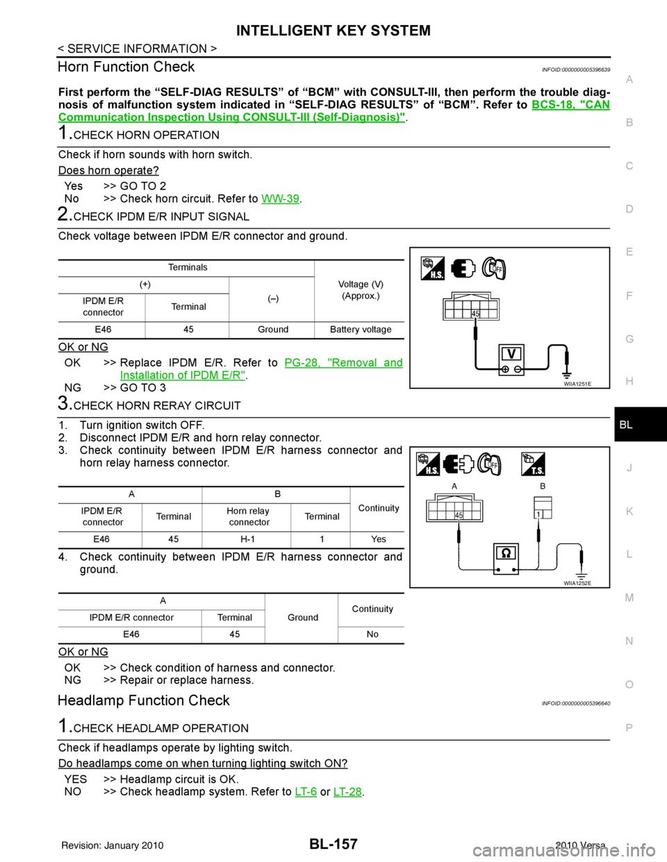
2.CHECK IPDM E/R INPUT SIGNAL
Check voltage between IPDM E/R connector and ground.
OK or NG
OK >> Replace IPDM E/R. Refer to PG-28, "Removal and
Installation of IPDM E/R".
NG >> GO TO 3
3.CHECK HORN RERAY CIRCUIT
1. Turn ignition switch OFF.
2. Disconnect IPDM E/R and horn relay connector.
3. Check continuity between IPDM E/R harness connector and horn relay harness connector.
4. Check continuity between IPDM E/R harness connector and ground.
OK or NG
OK >> Check condition of harness and connector.
NG >> Repair or replace harness.
Headlamp Function CheckINFOID:0000000005396640
1.CHECK HEADLAMP OPERATION
Check if headlamps operate by lighting switch.
Do headlamps come on when turning lighting switch ON?
YES >> Headlamp circuit is OK.
NO >> Check headlamp system. Refer to LT- 6
or LT- 2 8.
Te r m i n a l s
Voltage (V)(Approx.)
(+)
(–)
IPDM E/R
connector Te r m i n a l
E46 45Ground Ba ttery voltage
WIIA1251E
AB
Continuity
IPDM E/R
connector Te r m i n a l
Horn relay
connector Te r m i n a l
E46 45H-1 1Yes
A GroundContinuity
IPDM E/R connector Terminal
E46 45 No
WIIA1252E
Revision: January 20102010 Versa
Page 681 of 3745
BL-172
< SERVICE INFORMATION >
BACK DOOR LOCK
BACK DOOR LOCK
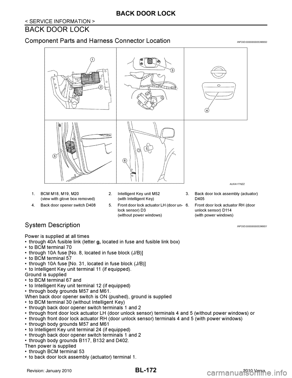
Component Parts and Harness Connector LocationINFOID:0000000005396650
System DescriptionINFOID:0000000005396651
Power is supplied at all times
• through 40A fusible link (letter g, located in fuse and fusible link box)
• to BCM terminal 70
• through 10A fuse [No. 8, located in fuse block (J/B)]
• to BCM terminal 57
• through 10A fuse [No. 31, located in fuse block (J/B)]
• to Intelligent Key unit terminal 11 (if equipped).
Ground is supplied
• to BCM terminal 67 and
• to Intelligent Key unit terminal 12 (if equipped)
• through body grounds M57 and M61.
When back door opener switch is ON (pushed), ground is supplied
• to BCM terminal 30 (without Intelligent Key)
• through back door opener switch terminals 1 and 2
• through front door lock actuator LH (door unlock s ensor) terminals 4 and 5 (without power windows) or
• through front door lock actuator RH (door unlock sensor) terminals 4 and 5 (with power windows)
• through body grounds M57 and M61
• to Intelligent Key unit terminal 24 (if equipped)
• through back door opener switch terminals 1 and 2
• through body grounds B117, B132 and D402.
Then power is supplied
• through BCM terminal 53
• to back door lock assembly (actuator) terminal 1.
ALKIA1776ZZ
1. BCM M18, M19, M20
(view with glove box removed) 2. Intelligent Key unit M52
(with Intelligent Key) 3. Back door lock assembly (actuator)
D405
4. Back door opener switch D408 5. Front door lock actuator LH (door un- lock sensor) D3
(without power windows)6. Front door lock actuator RH (door
unlock sensor) D114
(with power windows)
Revision: January 20102010 Versa
Page 682 of 3745
BACK DOOR LOCKBL-173
< SERVICE INFORMATION >
C
DE
F
G H
J
K L
M A
B
BL
N
O P
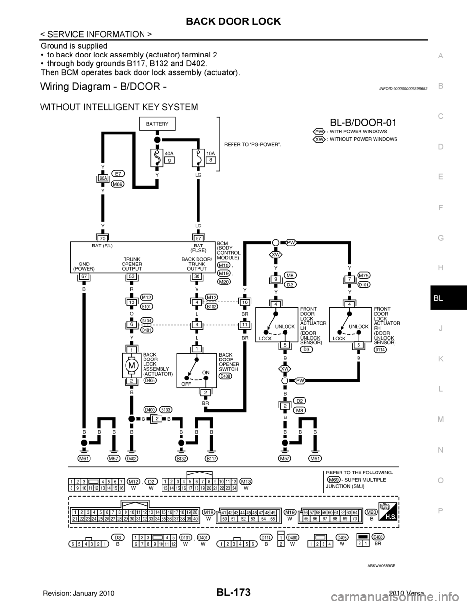
Ground is supplied
• to back door lock assembly (actuator) terminal 2
• through body grounds B117, B132 and D402.
Then BCM operates back door lock assembly (actuator).
Wiring Diagram - B/DOOR -INFOID:0000000005396652
WITHOUT INTELLIGENT KEY SYSTEM
ABKWA0689GB
Revision: January 20102010 Versa