2010 NISSAN TIIDA BCM
[x] Cancel search: BCMPage 565 of 3745
BL-56
< SERVICE INFORMATION >
POWER DOOR LOCK SYSTEM
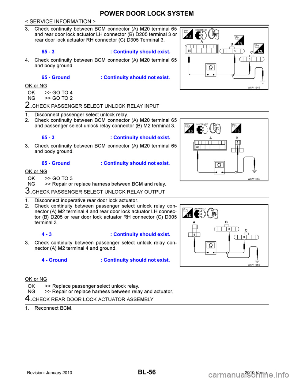
3. Check continuity between BCM connector (A) M20 terminal 65and rear door lock actuator LH connector (B) D205 terminal 3 or
rear door lock actuator RH connector (C) D305 Terminal 3.
4. Check continuity between BCM connector (A) M20 terminal 65 and body ground.
OK or NG
OK >> GO TO 4
NG >> GO TO 2
2.CHECK PASSENGER SELECT UNLOCK RELAY INPUT
1. Disconnect passenger select unlock relay.
2. Check continuity between BCM connector (A) M20 terminal 65 and passenger select unlock relay connector (B) M2 terminal 3.
3. Check continuity between BCM connector (A) M20 terminal 65 and body ground.
OK or NG
OK >> GO TO 3
NG >> Repair or replace harness between BCM and relay.
3.CHECK PASSENGER SELECT UNLOCK RELAY OUTPUT
1. Disconnect inoperative rear door lock actuator.
2. Check continuity between passenger select unlock relay con- nector (A) M2 terminal 4 and rear door lock actuator LH connec-
tor (B) D205 or rear door lock actuator RH connector (C) D305
terminal 3.
3. Check continuity between passenger select unlock relay con- nector (A) M2 terminal 4 and ground.
OK or NG
OK >> Replace passenger select unlock relay.
NG >> Repair or replace harness between relay and actuator.
4.CHECK REAR DOOR LOCK ACTUATOR ASSEMBLY
1. Reconnect BCM. 65 - 3
: Continuity should exist.
65 - Ground : Continuity should not exist.
WIIA1164E
65 - 3 : Continuity should exist.
65 - Ground : Continuity should not exist.
WIIA1165E
4 - 3 : Continuity should exist.
4 - Ground : Continuity should not exist.
WIIA1166E
Revision: January 20102010 Versa
Page 567 of 3745
BL-58
< SERVICE INFORMATION >
REMOTE KEYLESS ENTRY SYSTEM
REMOTE KEYLESS ENTRY SYSTEM
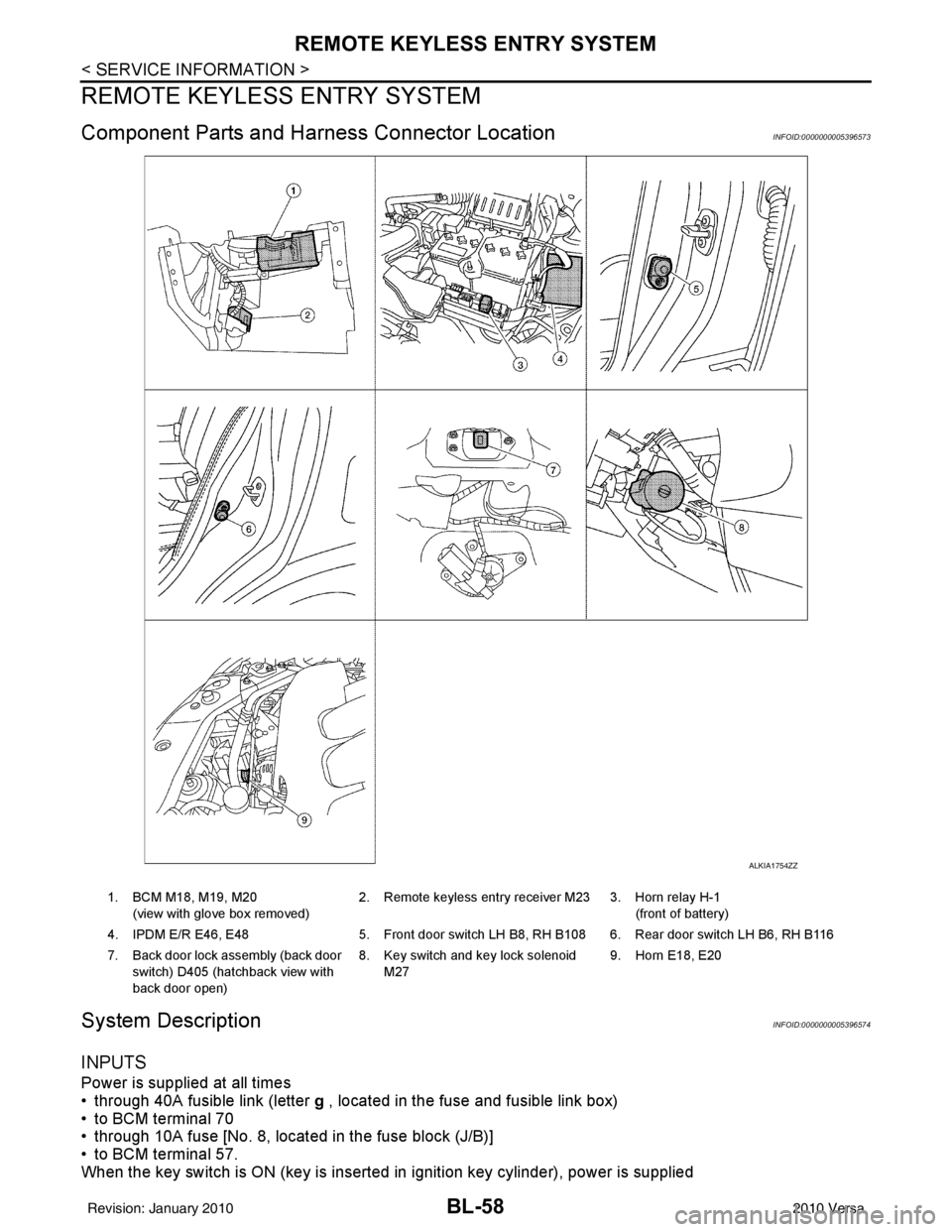
Component Parts and Harness Connector LocationINFOID:0000000005396573
System DescriptionINFOID:0000000005396574
INPUTS
Power is supplied at all times
• through 40A fusible link (letter g , located in the fuse and fusible link box)
• to BCM terminal 70
• through 10A fuse [No. 8, located in the fuse block (J/B)]
• to BCM terminal 57.
When the key switch is ON (key is inserted in ignition key cylinder), power is supplied
ALKIA1754ZZ
1. BCM M18, M19, M20
(view with glove box removed) 2. Remote keyless entry receiver M23 3. Horn relay H-1
(front of battery)
4. IPDM E/R E46, E48 5. Front door switch LH B8, RH B108 6. Rear door switch LH B6, RH B116
7. Back door lock assembly (back door switch) D405 (hatchback view with
back door open) 8. Key switch and key lock solenoid
M27 9. Horn E18, E20
Revision: January 20102010 Versa
Page 568 of 3745
![NISSAN TIIDA 2010 Service Repair Manual REMOTE KEYLESS ENTRY SYSTEMBL-59
< SERVICE INFORMATION >
C
DE
F
G H
J
K L
M A
B
BL
N
O P
• through 10A fuse [No. 14, located in the fuse block (J/B)]
• through key switch terminals 2 and 1
• to](/manual-img/5/57397/w960_57397-567.png "NISSAN TIIDA 2010 Service Repair Manual REMOTE KEYLESS ENTRY SYSTEMBL-59
< SERVICE INFORMATION >
C
DE
F
G H
J
K L
M A
B
BL
N
O P
• through 10A fuse [No. 14, located in the fuse block (J/B)]
• through key switch terminals 2 and 1
• to")
REMOTE KEYLESS ENTRY SYSTEMBL-59
< SERVICE INFORMATION >
C
DE
F
G H
J
K L
M A
B
BL
N
O P
• through 10A fuse [No. 14, located in the fuse block (J/B)]
• through key switch terminals 2 and 1
• to BCM terminal 37.
When the ignition switch is ACC or ON, power is supplied
• through 10A fuse [No. 20, located in the fuse block (J/B)]
• to BCM terminal 11.
Ground is supplied
• to BCM terminal 67
• through body grounds M57 and M61.
When the front door switch LH is ON (door is OPEN), ground is supplied
• to BCM terminal 47
• through front door switch LH terminal 2
• through front door switch LH case ground.
When the front door switch RH is ON (door is OPEN), ground is supplied
• to BCM terminal 12
• through front door switch RH terminal 2
• through front door switch RH case ground.
When the rear door switch LH is ON (door is OPEN), ground is supplied
• to BCM terminal 48
• through rear door switch LH terminal 1
• through rear door switch LH case ground.
When the rear door switch RH is ON (door is OPEN), ground is supplied
• to BCM meter terminal 13
• through rear door switch RH terminal 1
• through rear door switch RH case ground.
When the back door lock assembly (back door switch) (hat chback) is ON (back door is OPEN), ground is sup-
plied
• to BCM terminal 43
• through back door lock assembly (back door switch) terminals 3 and 4
• through body grounds B117, B132 and D402.
Keyfob signal is inputted to BCM from remote keyless entry receiver.
The remote keyless entry system controls operation of the
• power door lock
• hazard reminder
• auto door lock
• panic alarm
• room lamp
OPERATED PROCEDURE
Power Door Lock Operation
BCM receives a LOCK signal from keyfob. BCM locks all doors with input of LOCK signal from keyfob.
BCM receives a UNLOCK signal from keyfob. BCM unlocks all doors with input of UNLOCK signal from key-
fob.
Hazard and Horn Reminder
When the doors are locked or unlocked by keyfob, power is supplied to sound horn and flash hazard warning
lamps as follows
• LOCK operation: 3 or 4 mode (lamps flash twice)
• UNLOCK operation: 2 or 4 mode (lamps flash once)
• Horn sounds once with LOCK function when this feature is set ON.
The hazard reminder has modes 1, 2, 3 or 4. The hor n reminder can be turned ON/OFF with any LOCK mode.
Operating function of hazard reminder
Hazard and horn reminders do not operate if any door switch is ON (any door is OPEN).
How to change hazard and horn reminder modes
Mode 1Mode 2Mode 3 Mode 4
Keyfob operation Lock Unlock Lock Unlock Lock Unlock Lock Unlock
Hazard warning lamp
flash — — — Twice Once — Once Twice
Horn sound (ON/OFF) ON: once — O N: once — ON: once — ON: once —
Revision: January 20102010 Versa
Page 569 of 3745
BL-60
< SERVICE INFORMATION >
REMOTE KEYLESS ENTRY SYSTEM
With CONSULT-III
Hazard reminder can be changed using “HAZARD LAMP SET” mode in “WORK SUPPORT”.
Horn reminder can be changed using “HORN CHIRP SET” mode in “WORK SUPPORT”.
Refer to BL-69, "
CONSULT-III Function (BCM)" .
Without CONSULT-III
Refer to Owner's Manual for instructions.
Auto Door Lock Operation
Auto lock function signal is sent for operation when any of the following signals are not sent within 1 minute
after the unlock signal is sent from the keyfob:
• when door switch is turned ON for open.
• when the key switch is turned ON.
• when the lock signal is sent from the keyfob.
Auto door lock mode can be changed using “AUT O LOCK SET” mode in “WORK SUPPORT”.
Refer to BL-69, "
CONSULT-III Function (BCM)" .
Panic Alarm Operation
When key switch is OFF (when ignition key is not inserted in key cylinder), BCM turns on and off horn intermit-
tently with input of PANIC ALARM signal from keyfob.
BCM outputs to IPDM E/R for panic alarm signal (horn signal) as DATA LINE (CAN H line and CAN L line).
The alarm automatically turns off after 25 seconds or when BCM receives any signal from keyfob.
Panic alarm operation mode can be changed using “P ANIC ALARM SET” mode in “WORK SUPPORT”.
Refer to BL-69, "
CONSULT-III Function (BCM)" .
Interior Lamp Operation
When the following conditions come:
• condition of interior lamp switch is in the DOOR position;
• door switch OFF (when all the doors are closed);
Remote keyless entry system turns on interior lamp (for 30 seconds) with input of UNLOCK signal from key-
fob. For detailed description, refer to LT- 9 4
.
CAN Communication System DescriptionINFOID:0000000005396575
Refer to LAN-7 .
Revision: January 20102010 Versa
Page 574 of 3745
REMOTE KEYLESS ENTRY SYSTEMBL-65
< SERVICE INFORMATION >
C
DE
F
G H
J
K L
M A
B
BL
N
O P
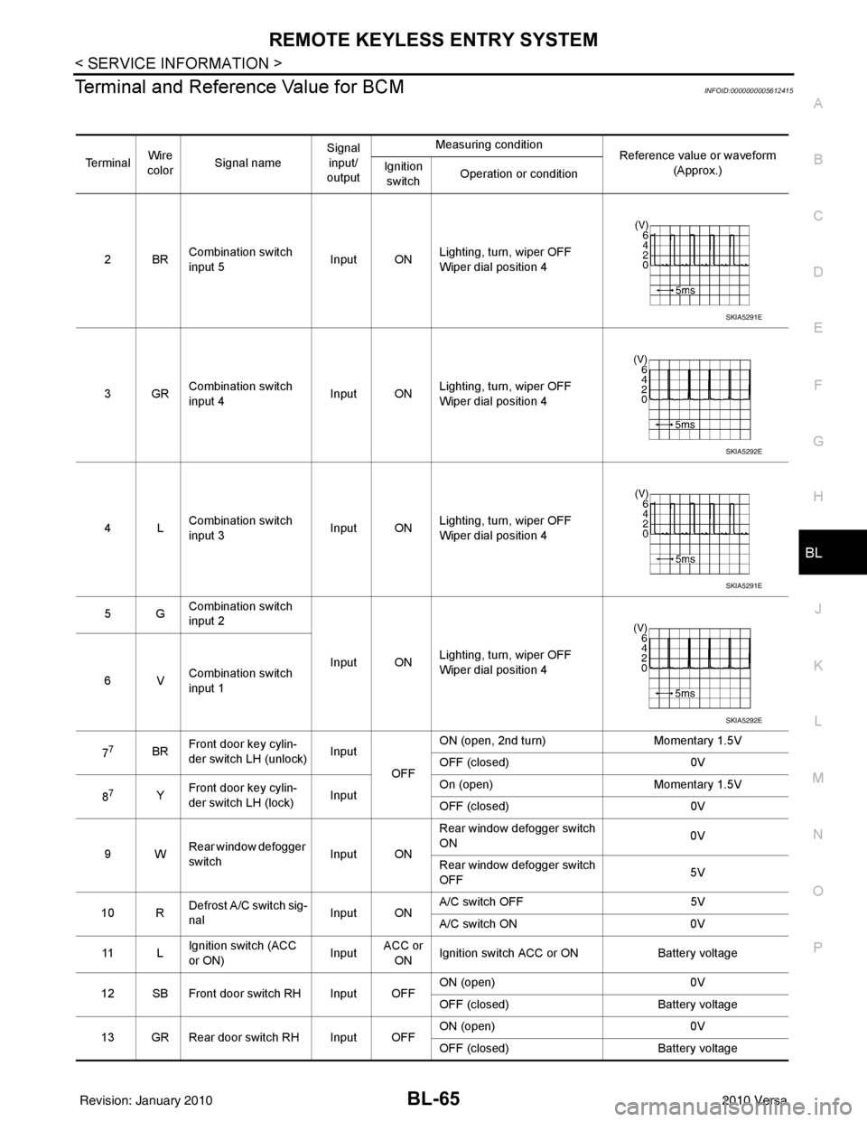
Terminal and Reference Value for BCMINFOID:0000000005612415
Te r m i n a l Wire
color Signal name Signal
input/
output Measuring condition
Reference value or waveform
(Approx.)
Ignition
switch Operation or condition
2BR Combination switch
input 5
Input ONLighting, turn, wiper OFF
Wiper dial position 4
3GR Combination switch
input 4 Input ONLighting, turn, wiper OFF
Wiper dial position 4
4L Combination switch
input 3
Input ONLighting, turn, wiper OFF
Wiper dial position 4
5G Combination switch
input 2
Input ONLighting, turn, wiper OFF
Wiper dial position 4
6V Combination switch
input 1
7
7BR Front door key cylin-
der switch LH (unlock) Input
OFFON (open, 2nd turn)
Momentary 1.5V
OFF (closed) 0V
8
7Y Front door key cylin-
der switch LH (lock) InputOn (open)
Momentary 1.5V
OFF (closed) 0V
9W Rear window defogger
switch Input ONRear window defogger switch
ON
0V
Rear window defogger switch
OFF 5V
10 R Defrost A/C switch sig-
nal
Input ONA/C switch OFF
5V
A/C switch ON 0V
11 L Ignition switch (ACC
or ON) InputACC or
ON Ignition switch ACC or ON
Battery voltage
12 SB Front door switch RH Input OFF ON (open)
0V
OFF (closed) Battery voltage
13 GR Rear door switch RH Input OFF ON (open)
0V
OFF (closed) Battery voltage
SKIA5291E
SKIA5292E
SKIA5291E
SKIA5292E
Revision: January 20102010 Versa
Page 578 of 3745
REMOTE KEYLESS ENTRY SYSTEMBL-69
< SERVICE INFORMATION >
C
DE
F
G H
J
K L
M A
B
BL
N
O P
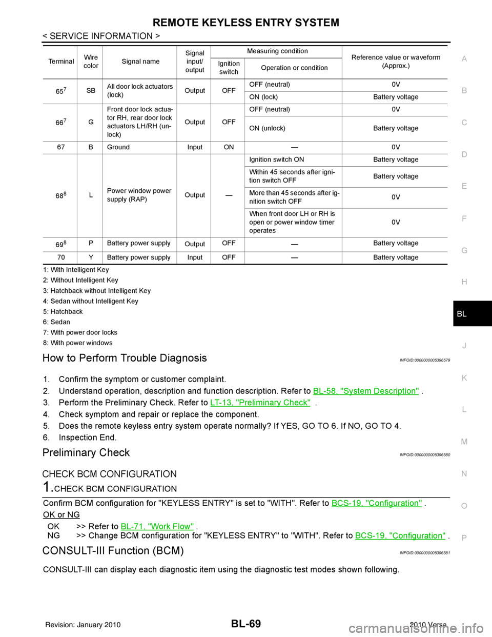
1: With Intelligent Key
2: Without Intelligent Key
3: Hatchback without Intelligent Key
4: Sedan without Intelligent Key
5: Hatchback
6: Sedan
7: With power door locks
8: With power windows
How to Perform Trouble DiagnosisINFOID:0000000005396579
1. Confirm the symptom or customer complaint.
2. Understand operation, description and function description. Refer to BL-58, "
System Description" .
3. Perform the Preliminary Check. Refer to LT-13, "
Preliminary Check" .
4. Check symptom and repair or replace the component.
5. Does the remote keyless entry system operate normally? If YES, GO TO 6. If NO, GO TO 4.
6. Inspection End.
Preliminary CheckINFOID:0000000005396580
CHECK BCM CONFIGURATION
1.CHECK BCM CONFIGURATION
Confirm BCM configuration for "KEYLESS ENTRY" is set to "WITH". Refer to BCS-19, "
Configuration" .
OK or NG
OK >> Refer to BL-71, "Work Flow" .
NG >> Change BCM configuration for "KEYLESS ENTRY" to "WITH". Refer to BCS-19, "
Configuration" .
CONSULT-III Function (BCM)INFOID:0000000005396581
CONSULT-III can display each diagnostic item using the diagnostic test modes shown following.
657SBAll door lock actuators
(lock) Output OFFOFF (neutral)
0V
ON (lock) Battery voltage
66
7G Front door lock actua-
tor RH, rear door lock
actuators LH/RH (un-
lock) Output OFFOFF (neutral)
0V
ON (unlock) Battery voltage
67 B Ground Input ON—0V
68
8L Power window power
supply (RAP)
Output —Ignition switch ON
Battery voltage
Within 45 seconds after igni-
tion switch OFF Battery voltage
More than 45 seconds after ig-
nition switch OFF 0V
When front door LH or RH is
open or power window timer
operates 0V
69
8P Battery power supply OutputOFF
— Battery voltage
70 Y Battery power supply Input OFF —Battery voltage
Te r m i n a l
Wire
color Signal name Signal
input/
output Measuring condition
Reference value or waveform
(Approx.)
Ignition
switch Operation or condition
Revision: January 20102010 Versa
Page 579 of 3745

BL-70
< SERVICE INFORMATION >
REMOTE KEYLESS ENTRY SYSTEM
CONSULT-III APPLICATION ITEMS
Work Support
PANIC ALARM SET
HAZARD LAMP BACK SET
AUTO LOCK SET
TRUNK OPEN
Data Monitor
Diagnostic modeDescription
WORK SUPPORT Supports inspections and adjustments. Commands are transmitted to the BCM for setting
the status suitable for required operation, input/output signals are received from the BCM
and received date is displayed.
DATA MONITOR Displays BCM input/output data in real time.
ACTIVE TEST Operation of electrical loads can be checked by sending drive signal to them.
SELF DIAGNOSTIC RESULT Displays BCM self-diagnosis results.
CAN DIAG SUPPORT MNTR The result of transmit/receive diagnosis of CAN communication can be read. ECU IDENTIFICATION BCM part number can be read.CONFIGURATION Performs BCM configuration read/write functions.
Test Item Description
REMO CONT ID REGIST Keyfob ID code can be registered.
REMO CONT ID ERASER Keyfob ID code can be erased.
REMO CONT ID CONFIR It can be checked whether keyfob ID code is registered or not in this mode.
PANIC ALRM SET Panic alarm operation mode can be changed in this mode. The operation mode will be
changed when
“CURRENT SETTING” on CONSUL T-III screen is touched.
HAZARD LAMP SET Hazard reminder mode can be changed in this mode. The hazard reminder mode will be
changed when
“CURRENT SETTING” on CONSUL T-III screen is touched.
AUTO LOCK SET Auto locking function mode can be changed in this mode. The function mode will be changed
when “CURRENT SETTING” on CONS
ULT-III screen is touched.
TRUNK OPEN Keyless trunk open operation mode can be changed in this mode. The operation mode will
be changed when “CURRENT SETTING” on CONSULT-III screen is touched.
MODE 1
MODE 2MODE 3
Keyfob operation 0.5 secondsNothing1.5 seconds
MODE 1 MODE 2MODE 3 MODE 4
Hazard lamp operation mode NothingUnlock only Lock only Lock and Unlock
MODE 1 MODE 2MODE 3
Auto locking function 30 secondsNothing1 minutes
MODE 1 MODE 2MODE 3
Keyfob operation 0.5 secondsNothing1.5 seconds
Monitored Item Description
IGN ON SW Indicates [ON/OFF] condition of ignition switch in ON position.
KEY ON SW Indicates [ON/OFF] condition of key switch.
ACC ON SW Indicates [ON/OFF] condition of ignition switch in ACC position.
KEYLESS LOCK Indicates [ON/OFF] condition of lock signal from keyfob.
KEYLESS UNLOCK Indicates [ON/OFF] condition of unlock signal from keyfob.
DOOR SW-DR Indicates [ON/OFF] condition of front door switch driver side.
DOOR SW-AS Indicates [ON/OFF] condition of front door switch passenger side.
Revision: January 20102010 Versa
Page 580 of 3745
REMOTE KEYLESS ENTRY SYSTEMBL-71
< SERVICE INFORMATION >
C
DE
F
G H
J
K L
M A
B
BL
N
O P
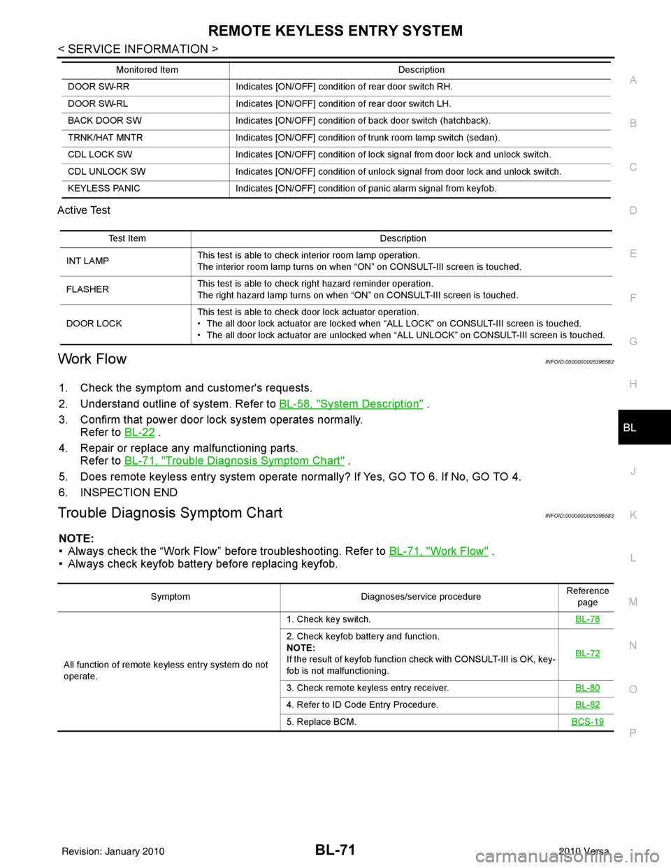
Active Test
Work FlowINFOID:0000000005396582
1. Check the symptom and customer's requests.
2. Understand outline of system. Refer to
BL-58, "
System Description" .
3. Confirm that power door lock system operates normally. Refer to BL-22
.
4. Repair or replace any malfunctioning parts. Refer to BL-71, "
Trouble Diagnosis Symptom Chart" .
5. Does remote keyless entry system operate normally? If Yes, GO TO 6. If No, GO TO 4.
6. INSPECTION END
Trouble Diagnosis Symptom ChartINFOID:0000000005396583
NOTE:
• Always check the “Work Flow” before troubleshooting. Refer to BL-71, "
Work Flow" .
• Always check keyfob battery before replacing keyfob.
DOOR SW-RR Indicates [ON/OFF] condition of rear door switch RH.
DOOR SW-RL Indicates [ON/OFF] condition of rear door switch LH.
BACK DOOR SW Indicates [ON/OFF] condition of back door switch (hatchback).
TRNK/HAT MNTR Indicates [ON/OFF] condition of trunk room lamp switch (sedan).
CDL LOCK SW Indicates [ON/OFF] condition of lock signal from door lock and unlock switch.
CDL UNLOCK SW Indicates [ON/OFF] condition of unlock signal from door lock and unlock switch.
KEYLESS PANIC Indicates [ON/OFF] condition of panic alarm signal from keyfob.
Monitored Item
Description
Test ItemDescription
INT LAMP This test is able to check interior room lamp operation.
The interior room lamp turns on when “ON” on CONSULT-III screen is touched.
FLASHER This test is able to check right hazard reminder operation.
The right hazard lamp turns on when “ON” on CONSULT-III screen is touched.
DOOR LOCK This test is able to check door lock actuator operation.
• The all door lock actuator are locked when “ALL LOCK” on CONSULT-III screen is touched.
• The all door lock actuator are unlocked when “ALL UNLOCK” on CONSULT-III screen is touched.
Symptom
Diagnoses/service procedureReference
page
All function of remote keyless entry system do not
operate. 1. Check key switch.
BL-78
2. Check keyfob battery and function.
NOTE:
If the result of keyfob function check with CONSULT-III is OK, key-
fob is not malfunctioning.BL-72
3. Check remote keyless entry receiver.
BL-80
4. Refer to ID Code Entry Procedure.BL-82
5. Replace BCM.BCS-19
Revision: January 20102010 Versa