2010 NISSAN TIIDA BCM
[x] Cancel search: BCMPage 534 of 3745
POWER DOOR LOCK SYSTEMBL-25
< SERVICE INFORMATION >
C
DE
F
G H
J
K L
M A
B
BL
N
O P
AUTOMATIC DOOR LOCKS (UNLOCK OPERATION)
The automatic door locks (UNLOCK) function is the function that unlocks all doors linked with the key position.
IGN OFF Interlock Door Unlock*1
For vehicles equipped with Intelligent Key system, all doors are unlocked when the power supply position is
changed from ON to OFF.
For vehicles not equipped with Intelligent Key system , all doors are unlocked when the mechanical key is
removed from the ignition key cylinder.
BCM outputs the unlock signal to all door lock actuator s when it detects that the power supply position is
changed from ignition switch ON to OFF (with Intelligent Key) or when the mechanical key is removed from the
ignition key cylinder (without Intelligent Key).
Setting change of Automatic Door Locks (UNLOCK) Function
The lock operation setting of the aut omatic door locks function can be changed.
With CONSULT-III
The ON/OFF switching of the automatic door locks (UNL OCK) function and the type selection of the automatic
door locks (UNLOCK) function can be performed at the WORK SUPPORT setting of CONSULT-III. Refer to
BL-41, "
CONSULT-III Function (BCM)".
Without CONSULT- III
The automatic door locks (UNLOCK) function can be sw itched ON/OFF by performing the following operation.
1. Close all doors (door switch OFF).
2. Turn ignition switch ON.
3. Within 20 seconds of turning the ignition switch ON, press and hold the door lock and unlock switch to the UNLOCK position for more than 5 seconds.
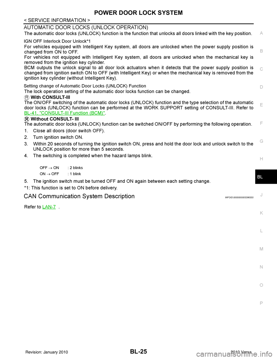
4. The switching is completed when the hazard lamps blink.
5. The ignition switch must be turned OFF and ON again between each setting change.
*1: This function is set to ON before delivery.
CAN Communication System DescriptionINFOID:0000000005396555
Refer to LAN-7 .
OFF → ON : 2 blinks
ON → OFF : 1 blink
Revision: January 20102010 Versa
Page 546 of 3745
POWER DOOR LOCK SYSTEMBL-37
< SERVICE INFORMATION >
C
DE
F
G H
J
K L
M A
B
BL
N
O P
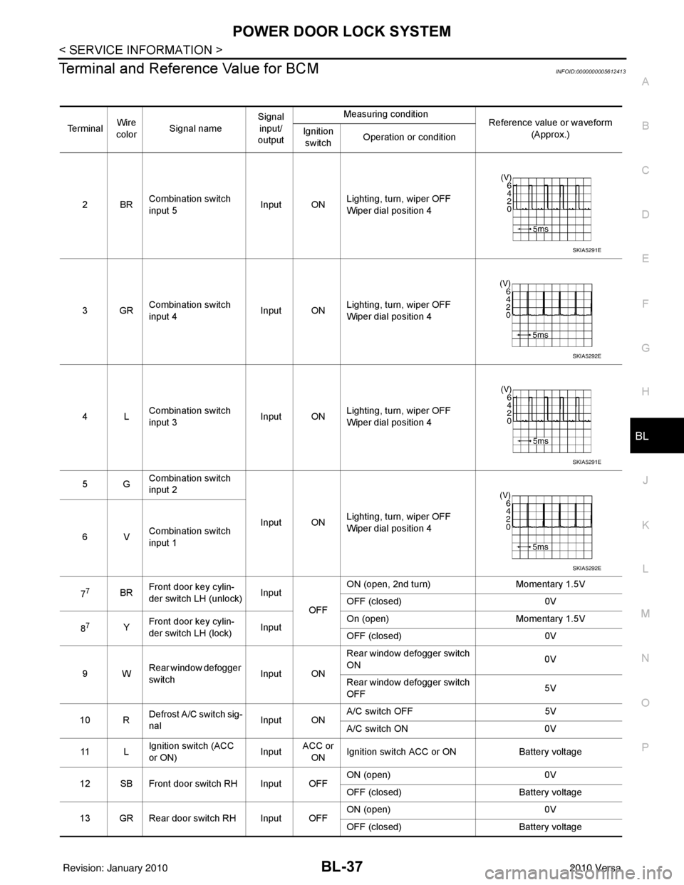
Terminal and Reference Value for BCMINFOID:0000000005612413
Te r m i n a l Wire
color Signal name Signal
input/
output Measuring condition
Reference value or waveform
(Approx.)
Ignition
switch Operation or condition
2BR Combination switch
input 5
Input ONLighting, turn, wiper OFF
Wiper dial position 4
3GR Combination switch
input 4 Input ONLighting, turn, wiper OFF
Wiper dial position 4
4L Combination switch
input 3
Input ONLighting, turn, wiper OFF
Wiper dial position 4
5G Combination switch
input 2
Input ONLighting, turn, wiper OFF
Wiper dial position 4
6V Combination switch
input 1
7
7BR Front door key cylin-
der switch LH (unlock) Input
OFFON (open, 2nd turn)
Momentary 1.5V
OFF (closed) 0V
8
7Y Front door key cylin-
der switch LH (lock) InputOn (open)
Momentary 1.5V
OFF (closed) 0V
9W Rear window defogger
switch Input ONRear window defogger switch
ON
0V
Rear window defogger switch
OFF 5V
10 R Defrost A/C switch sig-
nal
Input ONA/C switch OFF
5V
A/C switch ON 0V
11 L Ignition switch (ACC
or ON) InputACC or
ON Ignition switch ACC or ON
Battery voltage
12 SB Front door switch RH Input OFF ON (open)
0V
OFF (closed) Battery voltage
13 GR Rear door switch RH Input OFF ON (open)
0V
OFF (closed) Battery voltage
SKIA5291E
SKIA5292E
SKIA5291E
SKIA5292E
Revision: January 20102010 Versa
Page 550 of 3745

POWER DOOR LOCK SYSTEMBL-41
< SERVICE INFORMATION >
C
DE
F
G H
J
K L
M A
B
BL
N
O P
1: With Intelligent Key
2: Without Intelligent Key
3: Hatchback without Intelligent Key
4: Sedan without Intelligent Key
5: Hatchback
6: Sedan
7: With power door locks
8: With power windows
Work FlowINFOID:0000000005396561
1. Check the symptom and customer's requests.
2. Understand the outline of system. Refer to BL-23, "
System Description" .
3. According to the trouble diagnosis chart, repair or replace the cause of the malfunction. Refer to BL-119,
"Trouble Diagnosis Symptom Chart" .
4. Does power door lock system operate normally? OK: GO TO 5, NG: GO TO 3.
5. Inspection End.
CONSULT-III Function (BCM)INFOID:0000000005396562
CONSULT-III can display each diagnostic item using the diagnostic test modes shown following.
WORK SUPPORT
657SB All door lock actuators
(lock) Output OFFOFF (neutral)
0V
ON (lock) Battery voltage
66
7G Front door lock actua-
tor RH, rear door lock
actuators LH/RH (un-
lock) Output OFFOFF (neutral)
0V
ON (unlock) Battery voltage
67 B Ground Input ON—0V
68
8L Power window power
supply (RAP)
Output —Ignition switch ON
Battery voltage
Within 45 seconds after igni-
tion switch OFF Battery voltage
More than 45 seconds after ig-
nition switch OFF 0V
When front door LH or RH is
open or power window timer
operates 0V
69
8P Battery power supply OutputOFF
— Battery voltage
70 Y Battery power supply Input OFF —Battery voltage
Te r m i n a l
Wire
color Signal name Signal
input/
output Measuring condition
Reference value or waveform
(Approx.)
Ignition
switch Operation or condition
Diagnostic mode
Description
WORK SUPPORT Supports inspections and adjustments. Commands are transmitted to the BCM for setting the status
suitable for required operation, input/output signals are received from the BCM and received date
is displayed.
DATA MONITOR Displays BCM input/output data in real time. ACTIVE TEST Operation of electrical loads can be checked by sending drive signal to them.
SELF DIAGNOSTIC RESULT Displays BCM self-diagnosis results.
CAN DIAG SUPPORT MNTR The result of transmit/receive diagnosis of CAN communication can be read. ECU IDENTIFICATION BCM part number can be read.CONFIGURATION Performs BCM configuration read/write functions.
Revision: January 20102010 Versa
Page 552 of 3745
POWER DOOR LOCK SYSTEMBL-43
< SERVICE INFORMATION >
C
DE
F
G H
J
K L
M A
B
BL
N
O P
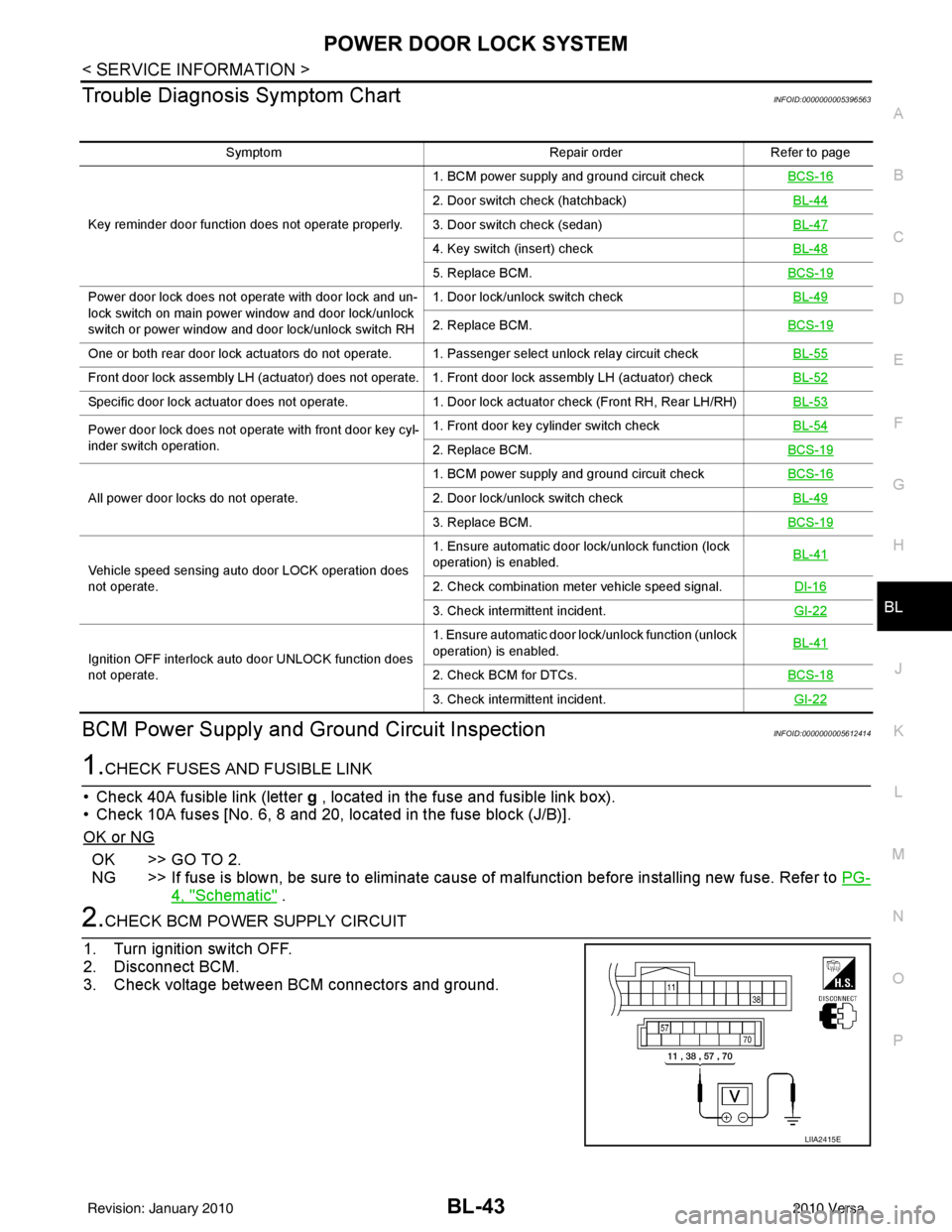
Trouble Diagnosis Symptom ChartINFOID:0000000005396563
BCM Power Supply and Gr ound Circuit InspectionINFOID:0000000005612414
1.CHECK FUSES AND FUSIBLE LINK
• Check 40A fusible link (letter g , located in the fuse and fusible link box).
• Check 10A fuses [No. 6, 8 and 20, lo cated in the fuse block (J/B)].
OK or NG
OK >> GO TO 2.
NG >> If fuse is blown, be sure to eliminate cause of malfunction before installing new fuse. Refer to PG-
4, "Schematic" .
2.CHECK BCM POWER SUPPLY CIRCUIT
1. Turn ignition switch OFF.
2. Disconnect BCM.
3. Check voltage between BCM connectors and ground.
Symptom Repair orderRefer to page
Key reminder door function does not operate properly. 1. BCM power supply and ground circuit check
BCS-16
2. Door switch check (hatchback) BL-44
3. Door switch check (sedan)BL-47
4. Key switch (insert) checkBL-48
5. Replace BCM.BCS-19
Power door lock does not operate with door lock and un-
lock switch on main power window and door lock/unlock
switch or power window and door lock/unlock switch RH1. Door lock/unlock switch check
BL-49
2. Replace BCM.BCS-19
One or both rear door lock actuators do not operate. 1. Passenger select unlock relay circuit check BL-55
Front door lock assembly LH (actuator) does not operate. 1. Front door lock assembly LH (actuator) checkBL-52
Specific door lock actuator does not operate.1. Door lock actuator check (Front RH, Rear LH/RH) BL-53
Power door lock does not operate with front door key cyl-
inder switch operation.1. Front door key cylinder switch check
BL-54
2. Replace BCM.BCS-19
All power door locks do not operate.1. BCM power supply and ground circuit check
BCS-162. Door lock/unlock switch check BL-49
3. Replace BCM.BCS-19
Vehicle speed sensing auto door LOCK operation does
not operate.1. Ensure automatic door lock/unlock function (lock
operation) is enabled.
BL-41
2. Check combination meter vehicle speed signal.
DI-16
3. Check intermittent incident.GI-22
Ignition OFF interlock auto door UNLOCK function does
not operate.1. Ensure automatic door lock/unlock function (unlock
operation) is enabled.
BL-41
2. Check BCM for DTCs.
BCS-18
3. Check intermittent incident. GI-22
LIIA2415E
Revision: January 20102010 Versa
Page 553 of 3745
BL-44
< SERVICE INFORMATION >
POWER DOOR LOCK SYSTEM
OK or NG
OK >> GO TO 3.
NG >> Repair or replace the harness.
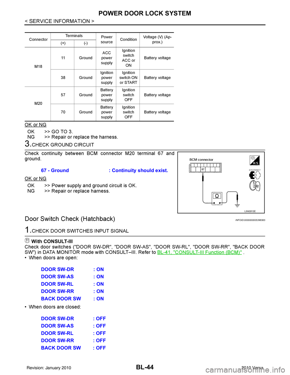
3.CHECK GROUND CIRCUIT
Check continuity between BCM connector M20 terminal 67 and
ground.
OK or NG
OK >> Power supply and ground circuit is OK.
NG >> Repair or replace harness.
Door Switch Check (Hatchback)INFOID:0000000005396565
1.CHECK DOOR SWITCHES INPUT SIGNAL
With CONSULT-III
Check door switches ("DOOR SW-DR", "DOOR SW-AS", "DOOR SW-RL", "DOOR SW-RR", "BACK DOOR
SW") in DATA MONITOR mode with CONSULT–III. Refer to BL-41, "
CONSULT-III Function (BCM)" .
• When doors are open:
• When doors are closed:
Connector Te r m i n a l s
Power
source Condition Voltage (V) (Ap-
prox.)
(+) (-)
M18 11 Ground
ACC
power
supply Ignition
switch
ACC or ON Battery voltage
38 Ground Ignition
power
supply Ignition
switch ON
or START Battery voltage
M20 57 Ground
Battery
power
supply Ignition
switch OFF Battery voltage
70 Ground Battery
power
supply Ignition
switch OFF Battery voltage
67 - Ground
: Continuity should exist.
LIIA0915E
DOOR SW-DR : ON
DOOR SW-AS : ON
DOOR SW-RL : ON
DOOR SW-RR : ON
BACK DOOR SW : ON
DOOR SW-DR : OFF
DOOR SW-AS : OFF
DOOR SW-RL : OFF
DOOR SW-RR : OFF
BACK DOOR SW : OFF
Revision: January 20102010 Versa
Page 554 of 3745
POWER DOOR LOCK SYSTEMBL-45
< SERVICE INFORMATION >
C
DE
F
G H
J
K L
M A
B
BL
N
O P
Without CONSULT-III
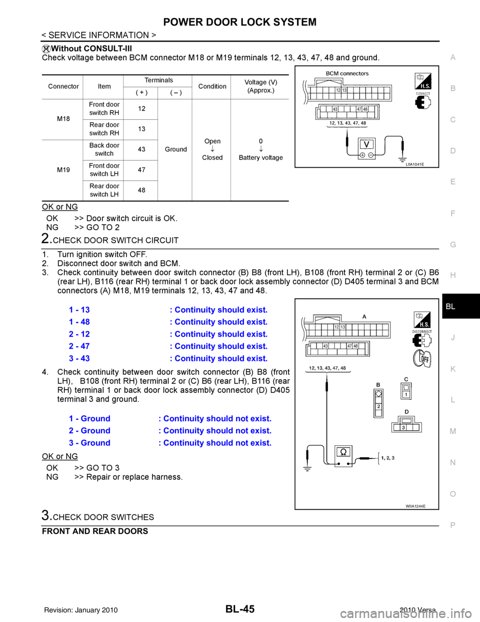
Check voltage between BCM connector M18 or M19 terminals 12, 13, 43, 47, 48 and ground.
OK or NG
OK >> Door switch circuit is OK.
NG >> GO TO 2
2.CHECK DOOR SWITCH CIRCUIT
1. Turn ignition switch OFF.
2. Disconnect door switch and BCM.
3. Check continuity between door switch connector (B) B8 (front LH), B108 (front RH) terminal 2 or (C) B6
(rear LH), B116 (rear RH) terminal 1 or back door lock assembly connector (D) D405 terminal 3 and BCM
connectors (A) M18, M19 te rminals 12, 13, 43, 47 and 48.
4. Check continuity between door switch connector (B) B8 (front LH), B108 (front RH) terminal 2 or (C) B6 (rear LH), B116 (rear
RH) terminal 1 or back door lo ck assembly connector (D) D405
terminal 3 and ground.
OK or NG
OK >> GO TO 3
NG >> Repair or replace harness.
3.CHECK DOOR SWITCHES
FRONT AND REAR DOORS
Connector Item Te r m i n a l s
ConditionVoltage (V)
(Approx.)
( + ) ( – )
M18 Front door
switch RH 12
Ground Open
↓
Closed 0
↓
Battery voltage
Rear door
switch RH 13
M19 Back door
switch 43
Front door switch LH 47
Rear door switch LH 48
LIIA1041E
1 - 13
: Continuity should exist.
1 - 48 : Continuity should exist.
2 - 12 : Continuity should exist.
2 - 47 : Continuity should exist.
3 - 43 : Continuity should exist.
1 - Ground : Continuity should not exist.
2 - Ground : Continuity should not exist.
3 - Ground : Continuity should not exist.
WIIA1244E
Revision: January 20102010 Versa
Page 555 of 3745
BL-46
< SERVICE INFORMATION >
POWER DOOR LOCK SYSTEM
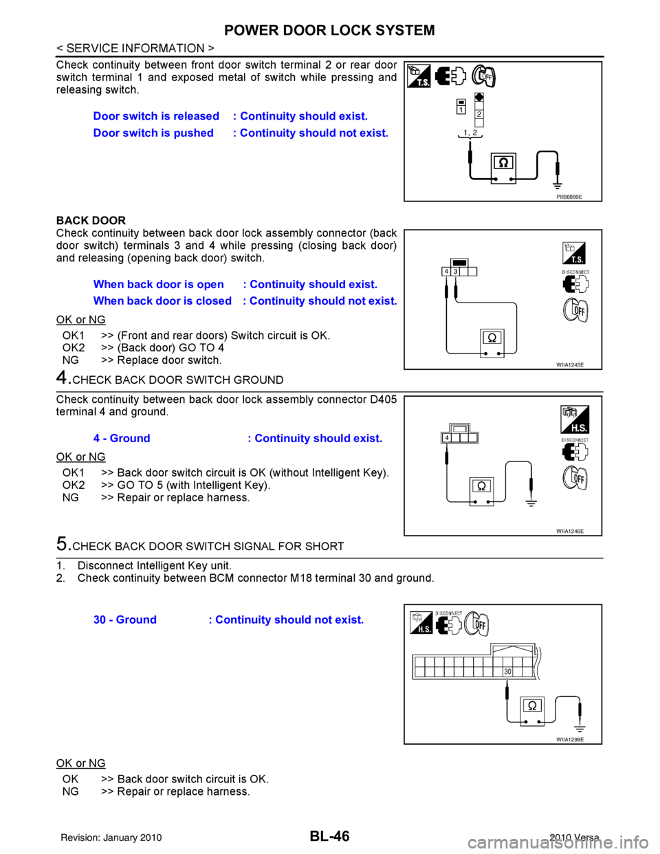
Check continuity between front door switch terminal 2 or rear door
switch terminal 1 and exposed metal of switch while pressing and
releasing switch.
BACK DOOR
Check continuity between back door lock assembly connector (back
door switch) terminals 3 and 4 while pressing (closing back door)
and releasing (opening back door) switch.
OK or NG
OK1 >> (Front and rear doors) Switch circuit is OK.
OK2 >> (Back door) GO TO 4
NG >> Replace door switch.
4.CHECK BACK DOOR SWITCH GROUND
Check continuity between back door lock assembly connector D405
terminal 4 and ground.
OK or NG
OK1 >> Back door switch circuit is OK (without Intelligent Key).
OK2 >> GO TO 5 (with Intelligent Key).
NG >> Repair or replace harness.
5.CHECK BACK DOOR SWITCH SIGNAL FOR SHORT
1. Disconnect Intelligent Key unit.
2. Check continuity between BCM connector M18 terminal 30 and ground.
OK or NG
OK >> Back door switch circuit is OK.
NG >> Repair or replace harness. Door switch is released :
Continuity should exist.
Door switch is pushed : Co ntinuity should not exist.
PIIB6899E
When back door is open : Continuity should exist.
When back door is closed : Co ntinuity should not exist.
WIIA1245E
4 - Ground: Continuity should exist.
WIIA1246E
30 - Ground : Continuity should not exist.
WIIA1299E
Revision: January 20102010 Versa
Page 556 of 3745
POWER DOOR LOCK SYSTEMBL-47
< SERVICE INFORMATION >
C
DE
F
G H
J
K L
M A
B
BL
N
O P
Door Switch Check (Sedan)INFOID:0000000005396566
1.CHECK DOOR SWITCHES INPUT SIGNALWith CONSULT-III
Check door switches ("DOOR SW-DR", "DOOR SW-AS" , "DOOR SW-RL", "DOOR SW-RR") in DATA MONI-
TOR mode with CONSULT–III. Refer to BL-41, "
CONSULT-III Function (BCM)" .
• When doors are open:
• When doors are closed:
Without CONSULT-III
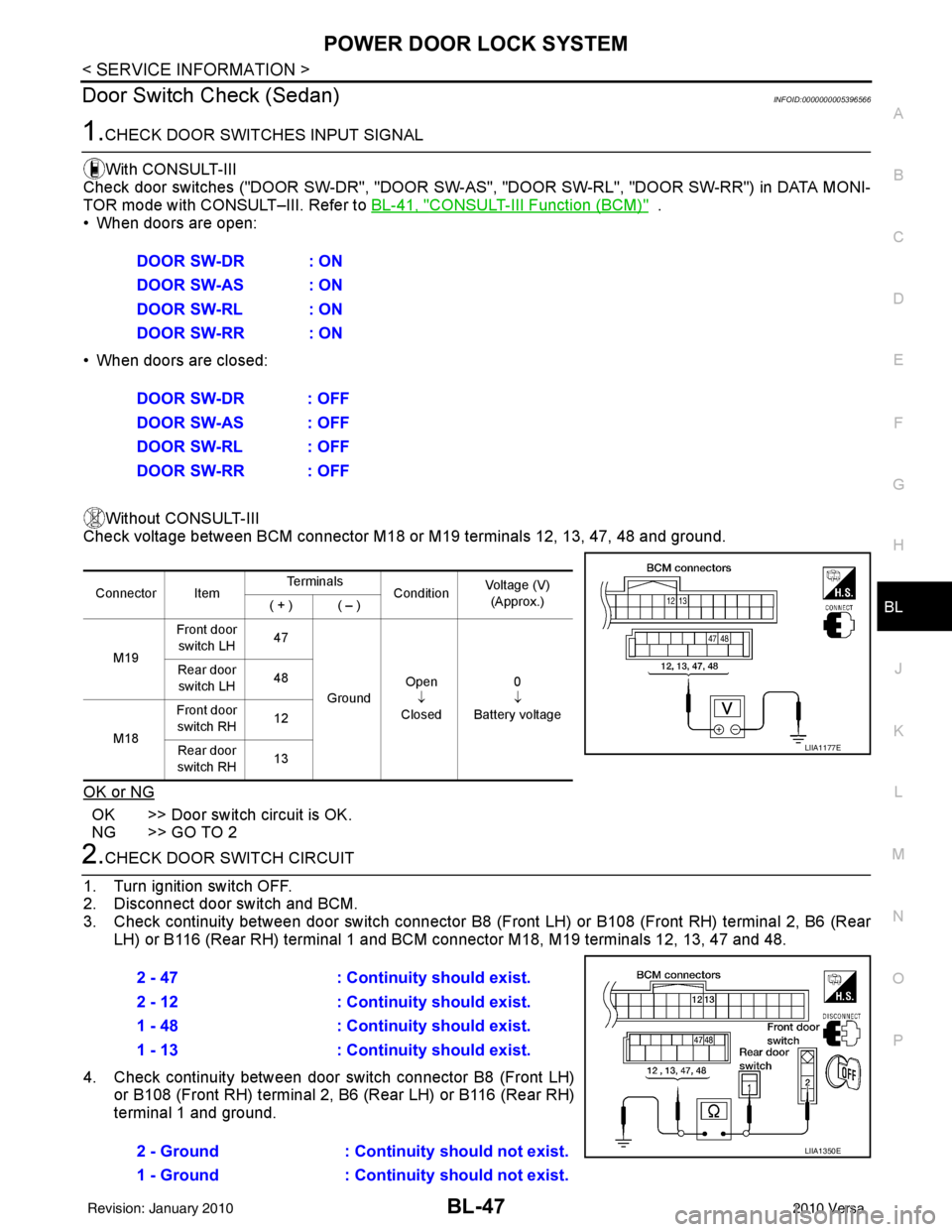
Check voltage between BCM connector M18 or M19 terminals 12, 13, 47, 48 and ground.
OK or NG
OK >> Door switch circuit is OK.
NG >> GO TO 2
2.CHECK DOOR SWITCH CIRCUIT
1. Turn ignition switch OFF.
2. Disconnect door switch and BCM.
3. Check continuity between door switch connector B8 (F ront LH) or B108 (Front RH) terminal 2, B6 (Rear
LH) or B116 (Rear RH) terminal 1 and BCM connector M18, M19 terminals 12, 13, 47 and 48.
4. Check continuity between door switch connector B8 (Front LH) or B108 (Front RH) terminal 2, B6 (Rear LH) or B116 (Rear RH)
terminal 1 and ground.DOOR SW-DR : ON
DOOR SW-AS : ON
DOOR SW-RL : ON
DOOR SW-RR : ON
DOOR SW-DR : OFF
DOOR SW-AS : OFF
DOOR SW-RL : OFF
DOOR SW-RR : OFF
Connector Item
Te r m i n a l s
ConditionVoltage (V)
(Approx.)
( + ) ( – )
M19 Front door
switch LH 47
Ground Open
↓
Closed 0
↓
Battery voltage
Rear door
switch LH 48
M18 Front door
switch RH 12
Rear door
switch RH 13
LIIA1177E
2 - 47
: Continuity should exist.
2 - 12 : Continuity should exist.
1 - 48 : Continuity should exist.
1 - 13 : Continuity should exist.
2 - Ground : Continuity should not exist.
1 - Ground : Continuity should not exist.
LIIA1350E
Revision: January 20102010 Versa