2010 NISSAN TIIDA Ei-22
[x] Cancel search: Ei-22Page 530 of 3745

FRONT FENDERBL-21
< SERVICE INFORMATION >
C
DE
F
G H
J
K L
M A
B
BL
N
O P
FRONT FENDER
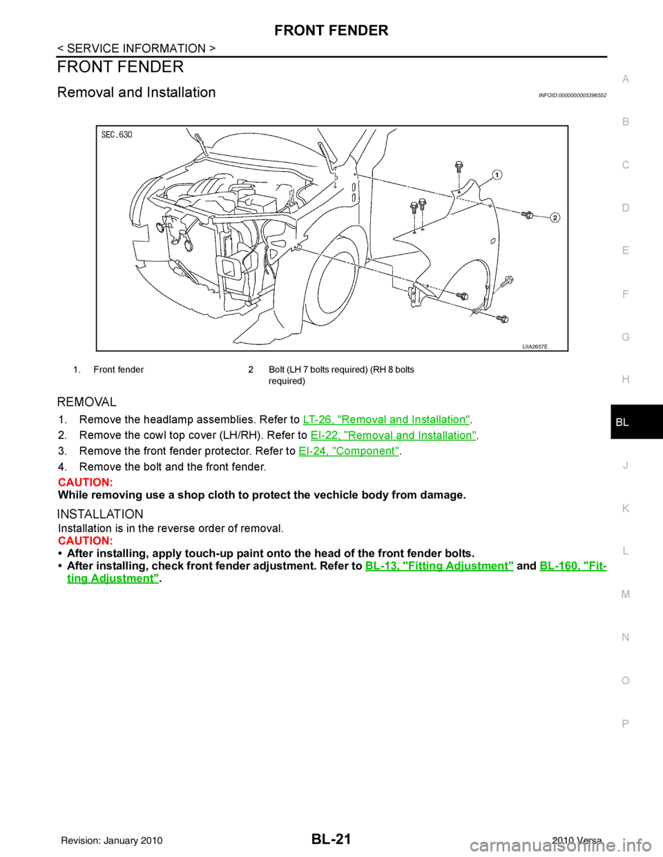
Removal and InstallationINFOID:0000000005396552
REMOVAL
1. Remove the headlamp assemblies. Refer to LT-26, "Removal and Installation".
2. Remove the cowl top cover (LH/RH). Refer to EI-22, "
Removal and Installation".
3. Remove the front fender protector. Refer to EI-24, "
Component".
4. Remove the bolt and the front fender.
CAUTION:
While removing use a shop cloth to pr otect the vechicle body from damage.
INSTALLATION
Installation is in the reverse order of removal.
CAUTION:
• After installing, apply touch-up paint on to the head of the front fender bolts.
• After installing, check front fender adjustment. Refer to BL-13, "
Fitting Adjustment" and BL-160, "Fit-
ting Adjustment".
1. Front fender 2 Bolt (LH 7 bolts required) (RH 8 bolts
required)
LIIA2657E
Revision: January 20102010 Versa
Page 862 of 3745

BR-14
< SERVICE INFORMATION >
DUAL PROPORTIONING VALVE
DUAL PROPORTIONING VALVE
Removal and InstallationINFOID:0000000005396987
Removal
1. Remove cowl top . Refer to EI-22, "Removal and Installation".
2. Disconnect brake lines from dual proportioning valve. • Mark brake lines for installation.
3. Remove dual proportioning valve bolt and dual proportioning valve.
4. Remove two bolts and bracket.
Installation
Installation is in the reverse order of removal.
• When installing brake lines to the dual proportioning valve, tighten to specifications. Refer to BR-11,
"Hydraulic Circuit".
InspectionINFOID:0000000005396988
CAUTION:
• Carefully monitor brake fluid level at master cylinder.
• Use the recommended new brake fluid. Refer to MA-14, "
Fluids and Lubricants".
• Be careful not to splash brake fluid on painted areas; it may cause paint damage. If brake fluid is
splashed on paint areas, wash it away with water immediately.
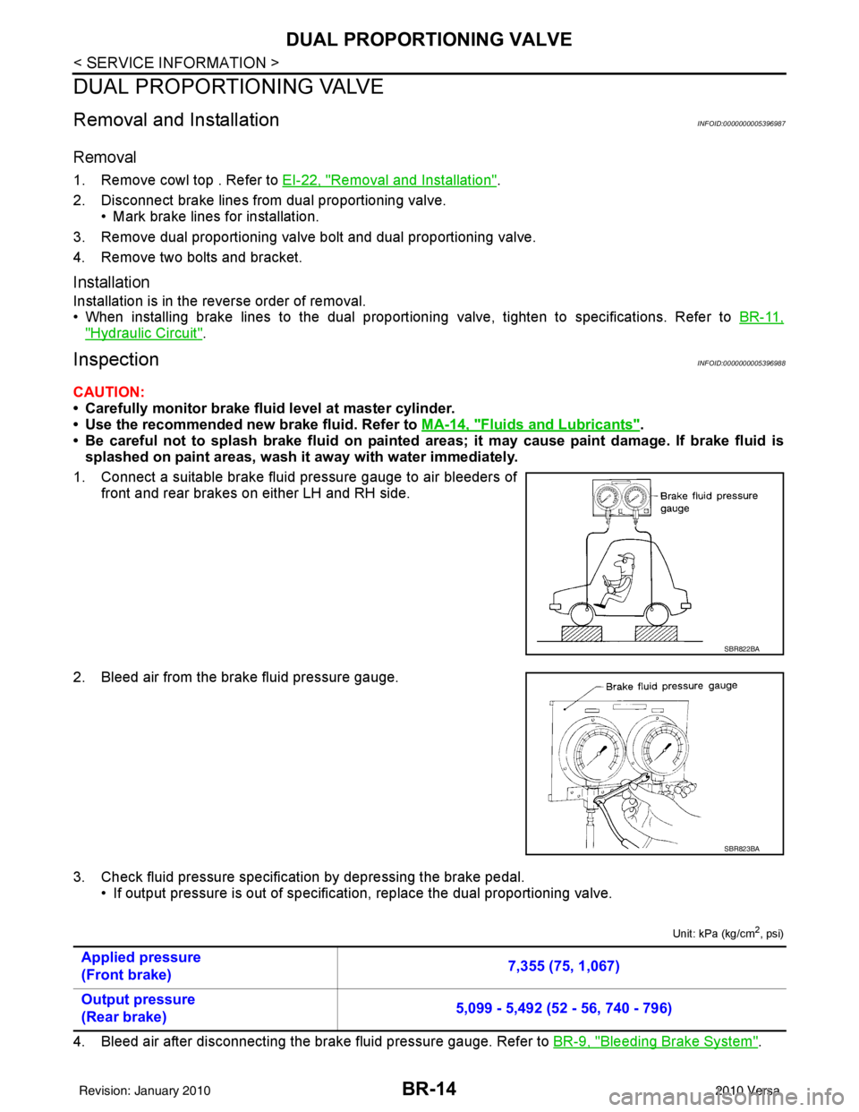
1. Connect a suitable brake fluid pressure gauge to air bleeders of front and rear brakes on either LH and RH side.
2. Bleed air from the brake fluid pressure gauge.
3. Check fluid pressure specific ation by depressing the brake pedal.
• If output pressure is out of specification, replace the dual proportioning valve.
Unit: kPa (kg/cm2, psi)
4. Bleed air after disconnecting the brake fluid pressure gauge. Refer to BR-9, "Bleeding Brake System".
SBR822BA
SBR823BA
Applied pressure
(Front brake) 7,355 (75, 1,067)
Output pressure
(Rear brake) 5,099 - 5,492 (52 - 56, 740 - 796)
Revision: January 20102010 Versa
Page 870 of 3745

BR-22
< SERVICE INFORMATION >
BRAKE BOOSTER
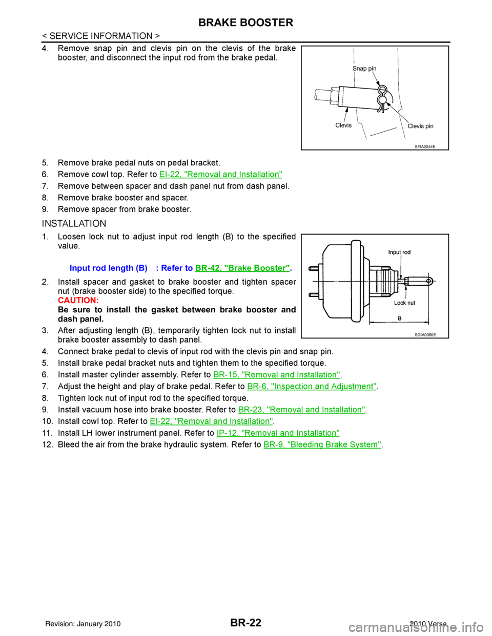
4. Remove snap pin and clevis pin on the clevis of the brakebooster, and disconnect the input rod from the brake pedal.
5. Remove brake pedal nuts on pedal bracket.
6. Remove cowl top. Refer to EI-22, "
Removal and Installation"
7. Remove between spacer and dash panel nut from dash panel.
8. Remove brake booster and spacer.
9. Remove spacer from brake booster.
INSTALLATION
1. Loosen lock nut to adjust input rod length (B) to the specified
value.
2. Install spacer and gasket to brake booster and tighten spacer nut (brake booster side) to the specified torque.
CAUTION:
Be sure to install the gasket between brake booster and
dash panel.
3. After adjusting length (B), temporarily tighten lock nut to install brake booster assembly to dash panel.
4. Connect brake pedal to clevis of input rod with the clevis pin and snap pin.
5. Install brake pedal bracket nuts and tighten them to the specified torque.
6. Install master cylinder assembly. Refer to BR-15, "
Removal and Installation".
7. Adjust the height and play of brake pedal. Refer to BR-6, "
Inspection and Adjustment".
8. Tighten lock nut of input rod to the specified torque.
9. Install vacuum hose into brake booster. Refer to BR-23, "
Removal and Installation".
10. Install cowl top. Refer to EI-22, "
Removal and Installation".
11. Install LH lower instrument panel. Refer to IP-12, "
Removal and Installation"
12. Bleed the air from the brake hydraulic system. Refer to BR-9, "Bleeding Brake System".
SFIA2044E
Input rod length (B) : Refer to BR-42, "Brake Booster".
SGIA0060E
Revision: January 20102010 Versa
Page 927 of 3745
![NISSAN TIIDA 2010 Service Repair Manual ACTUATOR AND ELECTRIC UNIT (ASSEMBLY)BRC-37
< SERVICE INFORMATION > [ABS]
C
D
E
G H
I
J
K L
M A
B
BRC
N
O P
ACTUATOR AND ELECTRIC UNIT (ASSEMBLY)
Removal and InstallationINFOID:0000000005397053
CAUTIO NISSAN TIIDA 2010 Service Repair Manual ACTUATOR AND ELECTRIC UNIT (ASSEMBLY)BRC-37
< SERVICE INFORMATION > [ABS]
C
D
E
G H
I
J
K L
M A
B
BRC
N
O P
ACTUATOR AND ELECTRIC UNIT (ASSEMBLY)
Removal and InstallationINFOID:0000000005397053
CAUTIO](/manual-img/5/57397/w960_57397-926.png)
ACTUATOR AND ELECTRIC UNIT (ASSEMBLY)BRC-37
< SERVICE INFORMATION > [ABS]
C
D
E
G H
I
J
K L
M A
B
BRC
N
O P
ACTUATOR AND ELECTRIC UNIT (ASSEMBLY)
Removal and InstallationINFOID:0000000005397053
CAUTION:
• Before servicing, disconnect battery negative terminal.
• To remove brake tube, use flare nut wrench to pr event flare nuts and brake tube from being dam-
aged. To install, use flare nut torque wrench, ti ghten flare nut to the specified torque. Refer to BR-11,
"Hydraulic Circuit".
• Do not apply excessive impact to ABS actuator and elect ric unit (control unit), such as dropping it.
• Do not remove and install actuator by holding harness.
• After work is completed, bleed the air from the brake hydraulic system. Refer to BR-9, "
Bleeding
Brake System".
REMOVAL
1. Disconnect the battery negative terminal.
2. Remove the cowl top. Refer to EI-22, "
Removal and Installation".
3. Disconnect ABS actuator and electric unit (control unit) connector.
4. Loosen brake tube flare nuts, then remove brake tubes from ABS actuator and electric unit (control unit).
5. Remove brake booster hose from engine. Refer to BR-23, "
Removal and Installation".
6. Remove ABS actuator and electric unit (control unit) bracket bolts.
7. Remove ABS actuator and electric unit (control unit).
1. To front right caliper 2. To rear left wheel cylinder 3. To rear right wheel cylinder
4. To front left caliper 5. From master cylinder primary side 6. From master cylinder secondary side
7. ABS actuator and electric unit (control unit) 8. Harness connector
Front
AWFIA0532GB
Revision: January 20102010 Versa
Page 979 of 3745
![NISSAN TIIDA 2010 Service Repair Manual ACTUATOR AND ELECTRIC UNIT (ASSEMBLY)BRC-89
< SERVICE INFORMATION > [VDC/TCS/ABS]
C
D
E
G H
I
J
K L
M A
B
BRC
N
O P
ACTUATOR AND ELECTRIC UNIT (ASSEMBLY)
Removal and InstallationINFOID:000000000561225 NISSAN TIIDA 2010 Service Repair Manual ACTUATOR AND ELECTRIC UNIT (ASSEMBLY)BRC-89
< SERVICE INFORMATION > [VDC/TCS/ABS]
C
D
E
G H
I
J
K L
M A
B
BRC
N
O P
ACTUATOR AND ELECTRIC UNIT (ASSEMBLY)
Removal and InstallationINFOID:000000000561225](/manual-img/5/57397/w960_57397-978.png)
ACTUATOR AND ELECTRIC UNIT (ASSEMBLY)BRC-89
< SERVICE INFORMATION > [VDC/TCS/ABS]
C
D
E
G H
I
J
K L
M A
B
BRC
N
O P
ACTUATOR AND ELECTRIC UNIT (ASSEMBLY)
Removal and InstallationINFOID:0000000005612259
CAUTION:
• Before servicing, disconnect battery negative terminal.
• To remove brake tube, use flare nut wrench to pr event flare nuts and brake tube from being dam-
aged. To install, use flare nut torque wrench, ti ghten flare nut to the specified torque. Refer to BR-11,
"Hydraulic Circuit".
• Do not apply excessive impact to ABS actuator and elect ric unit (control unit), such as dropping it.
• Do not remove and install actuator by holding harness.
• After work is completed, bleed the air from the brake hydraulic system. Refer to BR-9, "
Bleeding
Brake System".
REMOVAL
1. Disconnect the battery negative terminal.
2. Remove the cowl top. Refer to EI-22, "
Removal and Installation".
3. Disconnect ABS actuator and electric unit (control unit) connector.
4. Loosen brake tube flare nuts, then remove brake tubes from ABS actuator and electric unit (control unit).
5. Remove brake booster hose from engine. Refer to BR-23, "
Removal and Installation".
6. Remove ABS actuator and electric unit (control unit) bracket bolts.
7. Remove ABS actuator and electric unit (control unit).
1. To front right caliper 2. To rear left wheel cylinder 3. To rear right wheel cylinder
4. To front left caliper 5. From master cylinder primary side 6. From master cylinder secondary side
7. ABS actuator and electric unit (control unit) 8. Harness connector
Front
AWFIA0532GB
Revision: January 20102010 Versa
Page 2323 of 3745

EI-22
< ON-VEHICLE REPAIR >
COWL TOP
COWL TOP
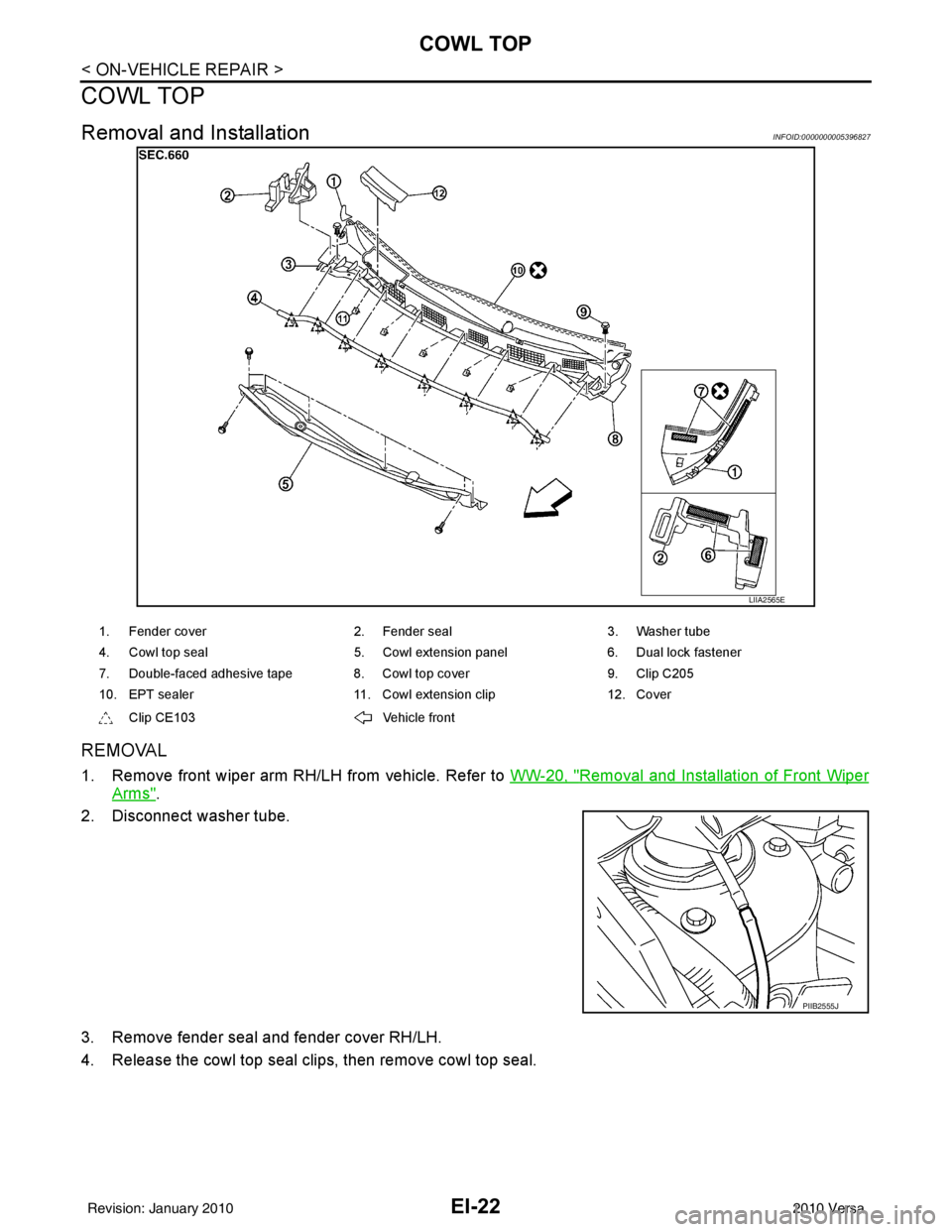
Removal and InstallationINFOID:0000000005396827
REMOVAL
1. Remove front wiper arm RH/LH from vehicle. Refer to WW-20, "Removal and Installation of Front Wiper
Arms".
2. Disconnect washer tube.
3. Remove fender seal and fender cover RH/LH.
4. Release the cowl top seal clips, then remove cowl top seal.
LIIA2565E
1. Fender cover 2. Fender seal3. Washer tube
4. Cowl top seal 5. Cowl extension panel6. Dual lock fastener
7. Double-faced adhesive tape 8. Cowl top cover 9. Clip C205
10. EPT sealer 11. Cowl extension clip12. Cover
Clip CE103 Vehicle front
PIIB2555J
Revision: January 20102010 Versa
Page 2390 of 3745
![NISSAN TIIDA 2010 Service Repair Manual EXHAUST MANIFOLDEM-31
< ON-VEHICLE REPAIR > [HR16DE]
C
D
E
F
G H
I
J
K L
M A
EM
NP
O
EXHAUST MANIFOLD
Exploded ViewINFOID:0000000005398052
Removal and InstallationINFOID:0000000005398053
REMOVAL
1. Re NISSAN TIIDA 2010 Service Repair Manual EXHAUST MANIFOLDEM-31
< ON-VEHICLE REPAIR > [HR16DE]
C
D
E
F
G H
I
J
K L
M A
EM
NP
O
EXHAUST MANIFOLD
Exploded ViewINFOID:0000000005398052
Removal and InstallationINFOID:0000000005398053
REMOVAL
1. Re](/manual-img/5/57397/w960_57397-2389.png)
EXHAUST MANIFOLDEM-31
< ON-VEHICLE REPAIR > [HR16DE]
C
D
E
F
G H
I
J
K L
M A
EM
NP
O
EXHAUST MANIFOLD
Exploded ViewINFOID:0000000005398052
Removal and InstallationINFOID:0000000005398053
REMOVAL
1. Remove the cowl. Refer to
EI-22, "Removal and Installation".
2. Remove heat insulator.
3. Remove exhaust front tube. Refer to EX-6, "
Component".
4. Remove the harness bracket of air fuel ratio sensor 1 from the cylinder head.
5. Remove exhaust manifold covers.
6. Remove the air fuel ratio sensor 1.
1. Exhaust manifold cover 2. Exhaust manifold cover3. Harness bracket
4. Air fuel ratio sensor 1 5. Exhaust manifold stay6. Exhaust manifold
7. Gasket 8. Stud bolt9. Heat insulator
: Engine front
PBIC4750E
Revision: January 20102010 Versa
Page 2442 of 3745
![NISSAN TIIDA 2010 Service Repair Manual ENGINE ASSEMBLYEM-83
< REMOVAL AND INSTALLATION > [HR16DE]
C
D
E
F
G H
I
J
K L
M A
EM
NP
O
• If items or work required are not covered by the engine section, follow the procedures in the applica-
bl NISSAN TIIDA 2010 Service Repair Manual ENGINE ASSEMBLYEM-83
< REMOVAL AND INSTALLATION > [HR16DE]
C
D
E
F
G H
I
J
K L
M A
EM
NP
O
• If items or work required are not covered by the engine section, follow the procedures in the applica-
bl](/manual-img/5/57397/w960_57397-2441.png)
ENGINE ASSEMBLYEM-83
< REMOVAL AND INSTALLATION > [HR16DE]
C
D
E
F
G H
I
J
K L
M A
EM
NP
O
• If items or work required are not covered by the engine section, follow the procedures in the applica-
ble sections.
• Always use the support poin t specified for lifting.
• Use either 2-pole lift type or separate type lift as best you can. If board-on type is used for unavoid-
able reasons, support at the rear axle jacking point with a transmission jack or similar tool before
starting work, in preparation for the backward shif t of center of gravity.
• For supporting points fo r lifting and jacking point at rear axle, refer to GI-38, "
Garage Jack and
Safety Stand and 2-Pole Lift".
REMOVAL
Outline
Remove the engine and the transaxle assembly from t he vehicle downward. Separate the engine and the tran-
saxle.
Preparation
1. Remove the hood assembly. Refer to BL-14, "Removal and Installation".
2. Remove the cowl top cover and cowl top extension assembly. Refer to EI-22, "
Removal and Installation".
3. Release fuel pressure. Refer to EC-496, "
Inspection".
4. Drain engine coolant from radiator. Refer to CO-12, "
Changing Engine Coolant".
CAUTION:
• Perform this step when the engine is cold.
• Never spill engine coolant on drive belt.
5. Drain the transmission fluid. Refer to MT-11, "
Draining" (M/T).
6. Remove the following parts. • Engine under cover. Refer to EI-15, "
Removal and Installation".
• Front road wheels and tires. Refer to WT-7, "
Adjustment".
• Front fender protector (RH and LH). Refer to EI-24, "
Removal and Installation".
• Battery and battery tray. Refer to SC-7, "
Removal and Installation".
• Drive belt. Refer to EM-15, "
Removal and Installation".
• Air duct and air cleaner case assembly. Refer to EM-26, "
Exploded View".
• Radiator hose (upper and lower). Refer to CO-17, "
Component".
• Disconnect cooling fan controller wiring harness.
• Remove coolant reservoir tank.
• Remove fan shroud and cooling fan assembly. Refer to CO-19, "
Component (Models with A/C)" or CO-
19, "Component (Models without A/C)".
Engine Room LH
1. Disconnect all connections of engine harness around the engine mounting insulator (LH), and then tem-
porarily secure the engine harness into the engine side.
CAUTION:
Protect connectors using a resin bag against foreign materials.
2. Remove ground cable at transaxle side.
3. Disconnect fuel feed hose at engine side. Refer to EM-34, "
Exploded View".
4. Disconnect EVAP purge hose and brake booster vacuum hose.
5. Disconnect heater hoses, and install plugs them to prevent engine coolant from draining. Refer to CO-17,
"Component".
6. Disconnect control linkage from transaxle. Refer to AT-213, "
A/T Shift Selector Removal and Installation"
(A/T), MT-14, "Exploded View" (M/T).
7. Disconnect the clutch tube at tr ansmission side (if equipped). Refer to CL-15, "
Removal and Installation".
Engine Room RH
1. Remove ground cable between front cover and vehicle.
2. Remove generator and generator br acket (A/C models). Refer to SC-25, "
Removal and Installation".
3. Remove A/C compressor with piping connected from t he engine. Temporarily secure it on the vehicle side
with a rope to avoid putting load on it (if equipped). Refer to MTC-79, "
Removal and Installation of Com-
pressor - HR16DE".
Vehicle Underbody
Revision: January 20102010 Versa