2010 NISSAN TIIDA Combination switch removal
[x] Cancel search: Combination switch removalPage 26 of 3745

PRECAUTIONSAT-9
< SERVICE INFORMATION >
DE
F
G H
I
J
K L
M A
B
AT
N
O P
• Gaskets, seals and O-rings should be replaced any time the A/T is disassembled.
• It is very important to perform func tional tests whenever they are indicated.
• The valve body contains precision parts and requires extreme care when parts are removed and serviced.
Place disassembled valve body parts in order for easier and proper assembly. Care will also prevent springs
and small parts from becoming scattered or lost.
• Properly installed valves, sleeves, plugs, etc. will slide along bores in valve body under their own weight.
• Before assembly, apply a coat of recommended ATF to all parts. Apply petroleum jelly to protect O-rings and seals, or hold bearings and washers in pl ace during assembly. Do not use grease.
• Extreme care should be taken to avoid damage to O-rings, seals and gaskets when assembling.
• Clean or replace ATF cooler if excessive foreign material is found in oil pan or clogging strainer. Refer to AT-
18, "A/T Fluid Cooler Cleaning".
• After overhaul, refill the A/T with new ATF.
• When the A/T drain plug is removed, only some of the fluid is drained. Old A/T fluid will remain in torque con- verter and ATF cooling system.
Always follow the procedures under “Changing A/T Fluid” in the AT section when changing A/T fluid. Refer to
AT-17, "
Changing A/T Fluid", AT-17, "Checking A/T Fluid".
Service Notice or PrecautionINFOID:0000000005397213
ATF COOLER SERVICE
If A/T fluid contains frictional material (clutches, bands, etc.), or if an A/T is repaired, overhauled, or replaced,
inspect and clean the A/T oil cooler mounted in the radiator or replace the radiator. Flush cooler lines using
cleaning solvent and compressed air after repair. Check Service Bulletins for latest A/T oil cooler cleaning pro-
cedure. For radiator replacement, refer to CO-17, "
Removal and Installation" (HR16DE engine models), CO-
41, "Removal and Installation" (MR18DE engine models).
TORQUE CONVERTER SERVICE
The torque converter should be replaced under any of the following conditions:
• External leaks in the hub weld area.
• Converter hub is scored or damaged.
• Converter pilot is broken, damaged or fits poorly into crankshaft.
• Steel particles are found after flushing the cooler and cooler lines.
• Pump is damaged or steel particles are found in the converter.
• Vehicle has TCC shudder and/or no TCC apply. Replace only after all hydraulic and electrical diagnoses
have been made. (Converter clutch material may be glazed.)
• Converter is contaminated with engi ne coolant containing antifreeze.
• Internal malfunction of stator roller clutch.
• Heavy clutch debris due to overheating (blue converter).
• Steel particles or clutch lining material found in flui d filter or on magnet when no internal parts in unit are
worn or damaged — indicates that lining material came from converter.
The torque converter should not be replaced if:
• The fluid has an odor, is discolored, and there is no evidence of metal or clutch facing particles.
• The threads in one or more of the converter bolt holes are damaged.
• A/T malfunction did not display evidence of damaged or worn internal parts, steel particles or clutch plate lin-
ing material in unit and inside the fluid filter.
• Vehicle has been exposed to high mileage (only). The e xception may be where the torque converter clutch
dampener plate lining has seen excess wear by vehicles operated in heavy and/or constant traffic, such as
taxi, delivery or police use.
OBD-II SELF-DIAGNOSIS
• A/T self-diagnosis is performed by the TCM in combination with the ECM. The results can be read through the blinking pattern of the OD OFF indicator lamp or the malfunction indicator lamp (MIL). Refer to the table
on AT-82, "
Diagnosis Procedure without CONSULT-III" for the indicator used to display each self-diagnostic
result.
• The self-diagnostic results indicated by the MIL are automatically stored in both the ECM and TCM memo- ries.
Always perform the procedure “HOW TO ERASE DTC” on AT-39, "
OBD-II Diagnostic Trouble Code
(DTC)" to complete the repair and avoid unnecessary blinking of the MIL.
• The following self-diagnostic items can be detected us ing ECM self-diagnostic results mode* only when the
OD OFF indicator lamp does not indicate any malfunctions.
- Transmission range switch
- A/T 1GR, 2GR, 3GR, or 4GR function
Revision: January 20102010 Versa
Page 466 of 3745
![NISSAN TIIDA 2010 Service Repair Manual AUDIOAV-69
< SERVICE INFORMATION > [AUDIO WITH NAVIGATION]
C
D
E
F
G H
I
J
L
M A
B
AV
N
O P
2.SPIRAL CABLE CHECK
1. Disconnect combination switch (spiral cable) connector M31.
2. Check continuity betw](/manual-img/5/57397/w960_57397-465.png "NISSAN TIIDA 2010 Service Repair Manual AUDIOAV-69
< SERVICE INFORMATION > [AUDIO WITH NAVIGATION]
C
D
E
F
G H
I
J
L
M A
B
AV
N
O P
2.SPIRAL CABLE CHECK
1. Disconnect combination switch (spiral cable) connector M31.
2. Check continuity betw")
AUDIOAV-69
< SERVICE INFORMATION > [AUDIO WITH NAVIGATION]
C
D
E
F
G H
I
J
L
M A
B
AV
N
O P
2.SPIRAL CABLE CHECK
1. Disconnect combination switch (spiral cable) connector M31.
2. Check continuity between combination switch (spiral cable) ter- minals.
OK or NG
OK >> GO TO 4.
NG >> Replace combination switch (spiral cable). Refer to SRS-37, "
Removal and Installation".
3.CHECK STEERING SWITCH RESISTANCE
Check resistance between combination switch (spiral cable) connector M31 terminals.
OK or NG
OK >> Inspection End.
NG >> Replace steering wheel audio control switch. Refer to AV-72, "
Removal and Installation".
Sound Is Not Heard from Front Door Speaker or Front TweeterINFOID:0000000005988550
1.HARNESS CHECK
1. Disconnect AV control unit connector and front door speaker and front tweeter connector (LH or RH).
16 - 32 : Continuity should exist.
17 - 31 : Continuity should exist.
20 - 24 : Continuity should exist.
WKIA4424E
Terminal Signal name
ConditionResistance
(Ω)
(Approx.)
16 17 Seek (down) Depress Seek down switch.
165
Phone/ Send Depress Phone/ Send switch. 0
Volume (down) Depress volume down switch. 652
20 17 Seek (up) Depress Seek up switch.
165
Phone/ End Depress Phone/ End switch. 0
Volume (up) Depress volume up switch. 652
LKIA0191E
Revision: January 20102010 Versa
Page 511 of 3745

BL-2
Keyfob Function (Unlock) Check ............................82
ID Code Entry Procedure .................................... ...82
Keyfob Battery Replacement ............................... ...85
Removal and Installation of Remote Keyless Entry
Receiver .............................................................. ...
85
INTELLIGENT KEY SYSTEM ............................86
Component Parts and Harness Connector Loca-
tion ....................................................................... ...
86
System Description .................................................88
CAN Communication System Description ..............95
Schematic ............................................................ ...96
Wiring Diagram - I/KEY - ..................................... ...98
Intelligent Key Unit Har ness Connector Terminal
Layout .................................................................. ..
108
Terminal and Reference Value for Intelligent Key
Unit ........................................................................
108
Steering Lock Solenoid Harness Connector Ter-
minal Layout ..........................................................
110
Terminal and Reference Value for Steering Lock
Solenoid .................................................................
110
Terminal and Reference Value for BCM ................111
Trouble Diagnosis Procedure ................................115
CONSULT-III Functions (INTELLIGENT KEY) ......117
CONSULT-III Application Item ............................. ..117
Trouble Diagnosis Symptom Chart ........................119
CAN Communication System Inspection ...............126
Power Supply and Ground Circuit Inspection ........126
Key Switch (Intelligent Key Unit Input) Check .......127
Key Switch (BCM Input) Check .............................128
Ignition Knob Switch Check ................................. ..129
Door Switch Check (Hatchback) ............................131
Door Switch Check (Sedan) ..................................133
Door Request Switch Check ..................................135
Back Door Request Switch Check (Hatchback) ....137
Trunk Opener Request Switch Check (Sedan) ... ..138
Unlock Sensor Check ............................................140
Intelligent Key Warning Buzzer(s) Check ..............142
Outside Key Antenna (Dri ver Side and Passenger
Side) Check ......................................................... ..
143
Outside Key Antenna (Rear Bumper) Check .........144
Inside Key Antenna Check ....................................146
Steering Lock Solenoid Check ............................ ..147
Key Interlock Solenoid (With M/T) Check ..............149
Ignition Switch Position Check ............................ ..150
Stop Lamp Switch Check (With CVT or A/T) ....... ..150
Stop Lamp Switch Check (With M/T) .....................152
CVT or A/T Shift Selector (Park Position Switch)
Check .................................................................. ..
153
"P-SHIFT" Warning Lamp (With CVT or A/T)
Check ....................................................................
154
"LOCK" Warning Lamp (With M/T) Check .............155
"KEY" Warning Lamp (RED) Check ......................155
"KEY" Warning Lamp (G REEN) Check .................155
Check Warning Chime in Combination Meter ........156
Hazard Function Check .........................................156
Horn Function Check .... .........................................157
Headlamp Function Chec k ....................................157
Intelligent Key Battery Replacement ................... ..158
Remote Keyless Entry Function ............................158
Removal and Installation of Intelligent Key Unit ... .158
DOOR ...............................................................160
Fitting Adjustment ................................................ .160
Removal and Installation .......................................163
FRONT DOOR LOCK ..................................... ..166
Component Parts Location .................................. .166
Removal and Installation .......................................166
REAR DOOR LOCK ....................................... ..169
Component Parts Location .................................. .169
Removal and Installation .......................................169
BACK DOOR LOCK ....................................... ..172
Component Parts and Harness Connector Loca-
tion ....................................................................... .
172
System Description ...............................................172
Wiring Diagram - B/DOOR - ..................................173
Terminal and Reference Value for BCM ...............175
Terminal and Reference Value for Intelligent Key
Unit ....................................................................... .
179
CONSULT-III Function (BCM) ..............................181
Work Flow .............................................................182
Trouble Diagnosis Chart by Symptom ..................182
BCM Power Supply and Ground Circuit Inspection
.
182
Check Back Door Opener Switch Circuit (Without
Intelligent Key or Power Windows) ...................... .
183
Check Back Door Opener Switch Circuit (Without
Intelligent Key, with Power Windows) .................. .
186
Check Back Door Opener Switch Circuit (With In-
telligent Key) ........................................................ .
188
Check Back Door Lock Assembly (Actuator) Cir-
cuit ........................................................................
190
Removal and Installation .......................................192
TRUNK LID ..................................................... ..193
Fitting Adjustment ................................................ .193
Trunk Lid Assembly ..............................................193
Trunk Lid Lock ......................................................194
Trunk Lid Striker ....................................................194
Trunk Lid Stay Disposal ........................................195
TRUNK LID OPENER .......................................196
Component Parts and Harness Connector Loca-
tion ....................................................................... .
196
System Description ...............................................196
Wiring Diagram - TLID - ........................................197
Terminal and Reference Value for BCM ...............199
Terminal and Reference Value for Intelligent Key
Unit ....................................................................... .
203
CONSULT-III Function (BCM) ..............................205
Work Flow .............................................................206
Trouble Diagnosis Chart by Symptom ..................206
BCM Power Supply and Ground Circuit Inspection
.
206
Check Trunk Lid Opener Switch Circuit (Without
Intelligent Key or Power Windows) ...................... .
207
Revision: January 20102010 Versa
Page 663 of 3745
BL-154
< SERVICE INFORMATION >
INTELLIGENT KEY SYSTEM
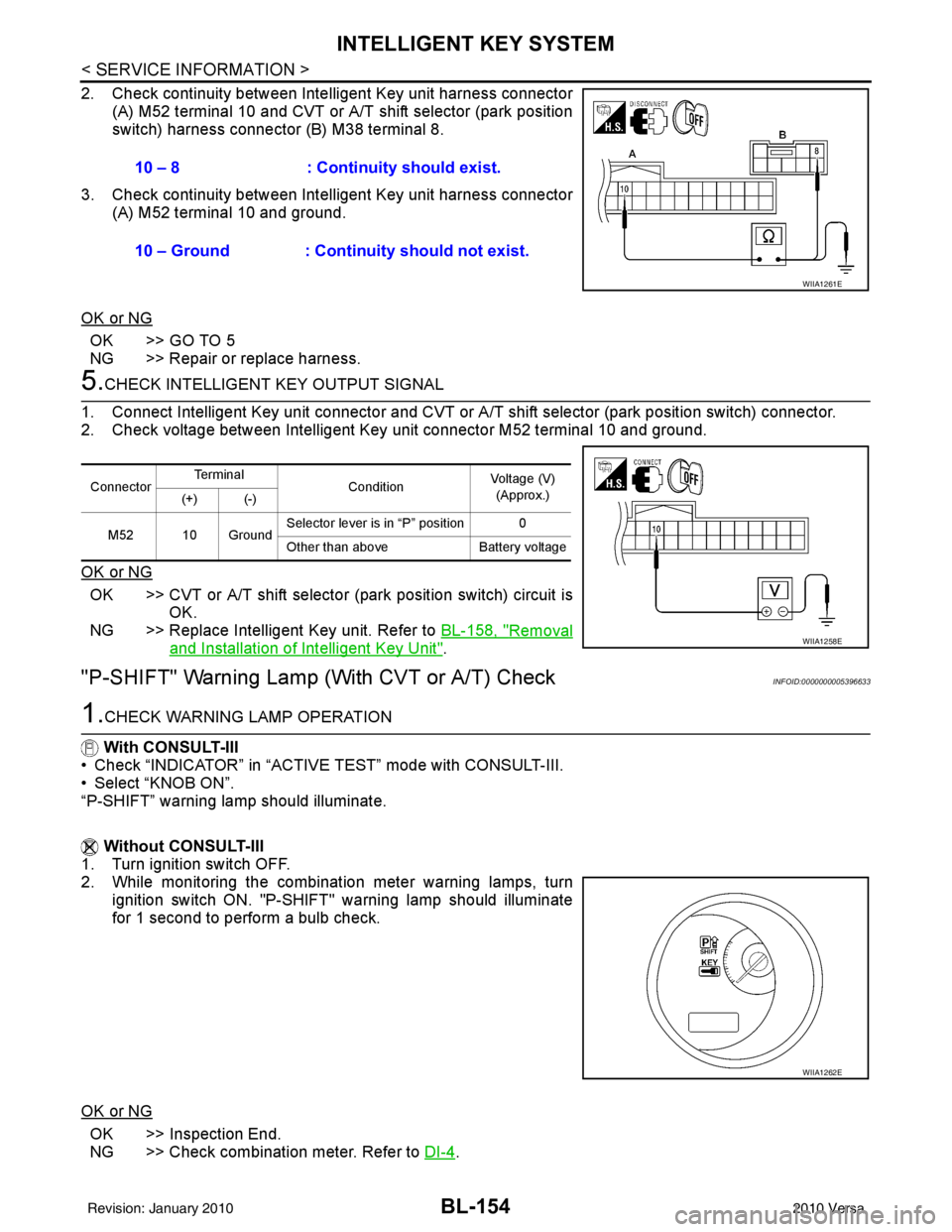
2. Check continuity between Intelligent Key unit harness connector
(A) M52 terminal 10 and CVT or A/T shift selector (park position
switch) harness connector (B) M38 terminal 8.
3. Check continuity between Inte lligent Key unit harness connector
(A) M52 terminal 10 and ground.
OK or NG
OK >> GO TO 5
NG >> Repair or replace harness.
5.CHECK INTELLIGENT KEY OUTPUT SIGNAL
1. Connect Intelligent Key unit connector and CVT or A/T shift selector (park position switch) connector.
2. Check voltage between Intelligent Key unit connector M52 terminal 10 and ground.
OK or NG
OK >> CVT or A/T shift selector (park position switch) circuit is
OK.
NG >> Replace Intelligent Key unit. Refer to BL-158, "
Removal
and Installation of Intelligent Key Unit".
"P-SHIFT" Warning Lamp (With CVT or A/T) CheckINFOID:0000000005396633
1.CHECK WARNING LAMP OPERATION
With CONSULT-III
• Check “INDICATOR” in “ACTIVE TEST” mode with CONSULT-III.
• Select “KNOB ON”.
“P-SHIFT” warning lamp should illuminate.
Without CONSULT-III
1. Turn ignition switch OFF.
2. While monitoring the combination meter warning lamps, turn
ignition switch ON. "P-SHIFT" warning lamp should illuminate
for 1 second to perform a bulb check.
OK or NG
OK >> Inspection End.
NG >> Check combination meter. Refer to DI-4
.
10 – 8 : Continuity should exist.
10 – Ground : Continuity should not exist.
WIIA1261E
Connector
Te r m i n a l
ConditionVoltage (V)
(Approx.)
(+) (-)
M52 10 Ground Selector lever is in “P” position 0
Other than above
Battery voltage
WIIA1258E
WIIA1262E
Revision: January 20102010 Versa
Page 774 of 3745
NATS (NISSAN ANTI-THEFT SYSTEM)BL-265
< SERVICE INFORMATION >
C
DE
F
G H
J
K L
M A
B
BL
N
O P
OK or NG
OK >> BCM is malfunctioning. • Replace BCM. Refer to BCS-19, "
Removal and Instal-
lation of BCM" .
• Perform initialization with CONSULT-III
• For initialization, refer to “CONSULT-III Operation Manual.
NG >> Check the following. • Harness for open or short between combination meter (security) and BCM
• Indicator lamp condition
Diagnosis Procedure 5INFOID:0000000005396715
Self-diagnostic results:
“LOCK MODE” displayed on CONSULT-III screen
1.CONFIRM SELF-DIAGNOSTIC RESULTS
Confirm SELF-DIAGNOSTIC RESULTS “LOCK MODE” is displayed on CONSULT-III screen.
Is
“LOCK MODE” displayed?
Yes >> GO TO 2
No >> GO TO BL-259, "
Trouble Diagnosis" .
2.ESCAPE FROM LOCK MODE
1. Turn ignition switch OFF.
2. Turn ignition switch ON with registered key. (Do not start engine.) Wait 5 seconds.
3. Return the key to OFF position. Wait 5 seconds.
4. Repeat steps 2 and 3 twice (total of three cycles).
5. Start the engine.
Does engine start?
Yes >> System is OK (Now system is escaped from “LOCK MODE”).
No >> GO TO 3
3.PERFORM INITIALIZATION WITH CONSULT-III
Perform initialization with CONSULT-III.
For initialization, refer to “CONSULT-III Operation Manual.
NOTE:
If the initialization is not completed or malf unctions, CONSULT-III shows the message on the screen.
Can the system be initialized?
Yes >> System is OK.
No >> GO TO 4
4.PERFORM INITIALIZATION WITH CONSULT-III AGAIN
1. Replace BCM.
2. Perform initialization with CONSULT-III. For initialization, refer to “CON SULT-III Operation Manual NATS”.
NOTE:
If the initialization is not completed or malf unctions, CONSULT-III shows the message on the screen.
Can the system be initialized?
Yes >> System is OK. (BCM is malfunctioning.)
No >> ECM is malfunctioning. • Replace ECM.
• Perform initialization with CONSULT-III
• For initialization, refer to “CONSULT-III Operation Manual NATS”
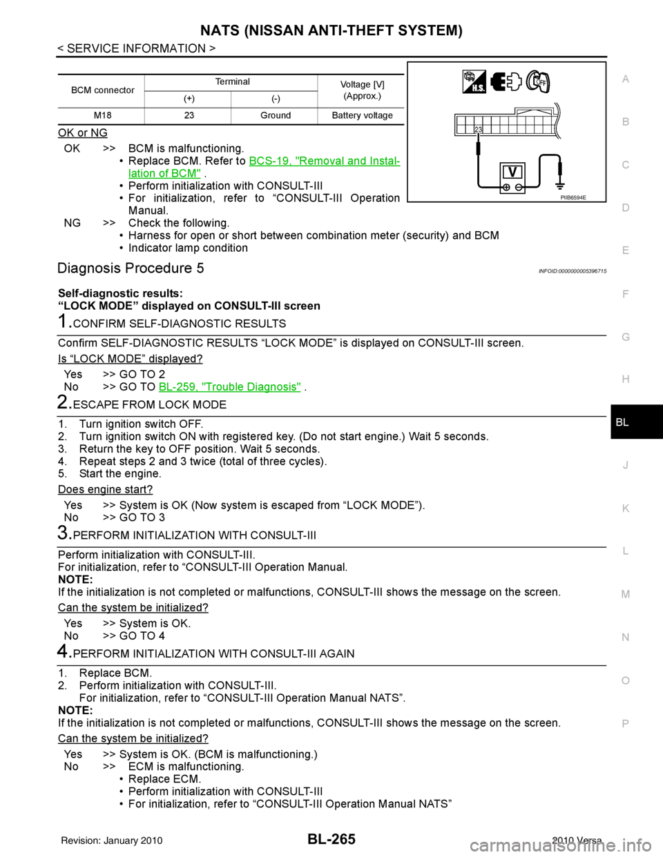
BCM connector Terminal
Voltage [V]
(Approx.)
(+) (-)
M18 23Ground Battery voltage
PIIB6594E
Revision: January 20102010 Versa
Page 909 of 3745
![NISSAN TIIDA 2010 Service Repair Manual TROUBLE DIAGNOSISBRC-19
< SERVICE INFORMATION > [ABS]
C
D
E
G H
I
J
K L
M A
B
BRC
N
O P
• If ABS actuator and electric unit (control unit) connec tion is loose, tighten the piping to the specified
t](/manual-img/5/57397/w960_57397-908.png "NISSAN TIIDA 2010 Service Repair Manual TROUBLE DIAGNOSISBRC-19
< SERVICE INFORMATION > [ABS]
C
D
E
G H
I
J
K L
M A
B
BRC
N
O P
• If ABS actuator and electric unit (control unit) connec tion is loose, tighten the piping to the specified
t")
TROUBLE DIAGNOSISBRC-19
< SERVICE INFORMATION > [ABS]
C
D
E
G H
I
J
K L
M A
B
BRC
N
O P
• If ABS actuator and electric unit (control unit) connec tion is loose, tighten the piping to the specified
torque and recheck for leaks.
• If there is damage to the connection flare nut or ABS actuator and electric unit (control unit) threads,
replace the damaged part and recheck for leaks.
• When there is fluid leaking or seeping from a fluid connection, use a clean cloth to wipe off the fluid and recheck for leaks. If fluid is still seeping out, replace the damaged part. If the fluid is leaking at the ABS
actuator and electric unit (control unit), replace the ABS actuator and electric unit (control unit) assem-
bly.
CAUTION:
The ABS actuator and electric unit (control unit) cannot be disassembl\
ed and must be replaced
as an assembly.
3. Check the brake pads for excessive wear.
POWER SYSTEM TERMINAL LOOSENESS AND BATTERY INSPECTION
Make sure the battery positive cable, negative cabl e and ground connection are not loose. In addition, make
sure the battery is sufficiently charged.
ABS WARNING LAMP INSPECTION
1. Make sure ABS warning lamp turns on for approximately 2 seconds when the ignition switch is turned ON. If it does not, check CAN communications. If ther e are no errors with the CAN communication system,
replace the combination meter. Refer to IP-12, "
Removal and Installation".
2. Make sure the lamp turns off approximately 2 seconds after the ignition switch is turned ON. If the lamp does not turn off, conduct self-diagnosis of ABS actuator and electric unit (control unit). If no malfunctions
are detected in self-diagnosis, replace combination meter. Refer to IP-12, "
Removal and Installation".
3. After conducting the self-diagnosis, be sure to erase the error memory. Refer to BRC-20, "
CONSULT-III
Function (ABS)".
Warning Lamp and Indicator TimingINFOID:0000000005397037
Note 1: Brake warning lamp will turn on when the parking brake is applied or when the brake fluid level is low.
x: ON
–: OFF
Control Unit Input/Out put Signal StandardINFOID:0000000005397038
REFERENCE VALUE FROM CONSULT-III
CAUTION:
The display shows the control unit calculation data, so a normal value might be displayed even in the
event the output circuit (harness) is open or short circuited.
Condition ABS
warning lamp BRAKE
warning lamp [Note 1] Remarks
When the ignition switch is OFF –– –
After the ignition switch is turned ON for approx. 1
second ××
–
After the ignition switch is turned ON for approx. 2
seconds ––Lamp goes off approx. 2 seconds after the
engine is started.
ABS malfunction ×––
EBD malfunction ××–
Revision: January 20102010 Versa
Page 1211 of 3745

DI-1
ELECTRICAL
C
DE
F
G H
I
J
L
M
SECTION DI
A
B
DI
N
O P
CONTENTS
DRIVER INFORMATION SYSTEM
SERVICE INFORMATION .. ..........................2
PRECAUTION ................................................ .....2
Precaution for Supplemental Restraint System
(SRS) "AIR BAG" and "SEAT BELT PRE-TEN-
SIONER" ............................................................. ......
2
Precaution Necessary for Steering Wheel Rota-
tion After Battery Disconnect ............................... ......
2
COMBINATION METERS ...................................4
Component Parts and Harness Connector Loca-
tion ...................................................................... ......
4
System Description ...................................................4
Arrangement of Combination Meter ..........................6
Internal Circuit ...........................................................7
Wiring Diagram - METER - .......................................8
Combination Meter Harness Connector Terminal
Layout .....................................................................
10
Terminal and Reference Value for Combination
Meter .......................................................................
10
Self-Diagnosis Mode of Combination Meter ........ ....11
CONSULT-III Function (METER/M&A) ............... ....13
Trouble Diagnosis ...................................................14
Symptom Chart .......................................................15
Power Supply and Ground Circuit Inspection .........15
Vehicle Speed Signal Inspection .............................16
Engine Speed Signal Inspection .............................17
Fuel Level Sensor Signal Inspection .......................17
Fuel Gauge Fluctuates, Indicates Wrong Value, or
Varies ......................................................................
19
Fuel Gauge Does Not Move to Full-position ...........19
DTC [U1000] CAN Communication Circuit ......... ....19
Electrical Component Inspection .............................20
Removal and Installation .........................................20
WARNING LAMPS ......................................... ....21
Schematic ........................................................... ....21
Wiring Diagram - WARN - ................................... ....22
Oil Pressure Warning Lamp Stays Off (Ignition
Switch ON) .......................................................... ....
30
Oil Pressure Warning Lamp Does Not Turn Off
(Oil Pressure Is Normal) ...................................... ....
32
Component Inspection .............................................32
A/T INDICATOR ................................................34
System Description ..................................................34
Wiring Diagram - AT/IND - .......................................35
A/T Indicator Does Not Illuminate ............................36
CVT INDICATOR ...............................................38
System Description ..................................................38
Schematic ................................................................38
Wiring Diagram - CVTIND - .....................................39
CVT Indicator Does Not Illuminate ..........................41
WARNING CHIME .............................................43
Component Parts and Harness Connector Loca-
tion ....................................................................... ....
43
System Description ..................................................43
Wiring Diagram - CHIME - .......................................46
Terminal and Reference Value for BCM ..................47
CONSULT-III Function (B CM) .................................47
Trouble Diagnosis ................................................ ....48
Combination Meter Buzzer Circuit Inspection .........49
Front Door Switch LH Signal Inspection .............. ....50
Key Switch Signal Inspection (Without Intelligent
Key) ..................................................................... ....
51
Key Switch and Ignition Knob Switch Signal In-
spection (With Intelligent Key, When Mechanical
Key Is Used) ........................................................ ....
52
Lighting Switch Signal Inspection ............................54
Parking Brake Switch Signal Inspection ..................54
Electrical Component Inspection .............................55
Revision: January 20102010 Versa
Page 1222 of 3745
DI-12
< SERVICE INFORMATION >
COMBINATION METERS
If the diagnosis function is activated with “trip A” displayed, the mileage on “trip A” will indicate “0000.0”,
but the actual trip mileage will be retained. (The same applies for “trip B”.)
2. Turn ignition switch OFF.
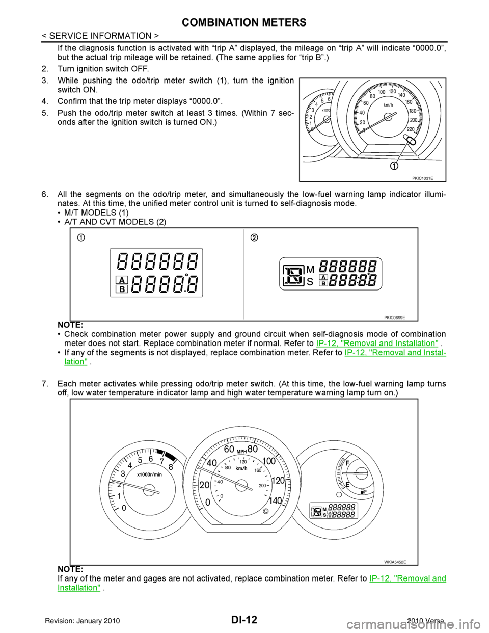
3. While pushing the odo/trip meter switch (1), turn the ignition switch ON.
4. Confirm that the trip meter displays “0000.0”.
5. Push the odo/trip meter switch at least 3 times. (Within 7 sec- onds after the ignition switch is turned ON.)
6. All the segments on the odo/trip meter, and simultaneously the low-fuel warning lamp indicator illumi- nates. At this time, the unified meter control unit is turned to self-diagnosis mode.
• M/T MODELS (1)
• A/T AND CVT MODELS (2)
NOTE:
• Check combination meter power supply and ground circuit when self-diagnosis mode of combination
meter does not start. Replace combination meter if normal. Refer to IP-12, "
Removal and Installation" .
• If any of the segments is not displayed, replace combination meter. Refer to IP-12, "
Removal and Instal-
lation" .
7. Each meter activates while pressing odo/trip meter switch. (At this time, the low-fuel warning lamp turns off, low water temperature indicator lamp and high water temperature warning lamp turn on.)
NOTE:
If any of the meter and gages are not activat ed, replace combination meter. Refer to IP-12, "
Removal and
Installation" .
PKIC1031E
PKIC0699E
WKIA5452E
Revision: January 20102010 Versa