Page 508 of 3745

BCM (BODY CONTROL MODULE)BCS-19
< SERVICE INFORMATION >
C
DE
F
G H
I
J
L
M A
B
BCS
N
O P
Contents displayed
No malfunction>>Inspection End
Malfunction in CAN communication system>>After printing the monitor items, go to “CAN System”. Refer to
LAN-17, "
Trouble Diagnosis Flow Chart".
ConfigurationINFOID:0000000005395111
DESCRIPTION
CONFIGURATION has three functions as follows:
• READ CONFIGURATION is the function to read (e xtract) vehicle configuration of current BCM.
• WRITE CONFIGURATION-Manual selection is the functi on to select and write vehicle configuration on BCM
manually.
• WRITE CONFIGURATION-Config file is the function to write vehicle configuration with the data extracted
from current BCM.
• For READ CONFIGURATION and WRITE CONFIGURATION -Config file, refer to CONSULT-III Operation
Manual.
• For WRITE CONFIGURATION-Manual selection using the following flow chart, identify the correct model
and configuration list. Confirm and/or change setting val ue for each item according to the configuration list.
Depending on CONSULT-III software version being used, some or all of the write configuration items shown
in the following configuration lists may be display ed. If an item does not appear on the CONSULT-III WRITE
CONFIGURATION-Manual selection screen(s), then it is an auto setting item and it cannot be manually set
or changed.
NOTE:
Confirm vehicle model on IDENTIFICATION PLATE. Refer to GI-43, "
Model Variation".
CAUTION:
• When replacing BCM, you must perform WRITE CONFIGURATION with CONSULT-III.
• Complete the procedure of WRITE CONFIGURATION in order.
• If you set incorrect WRITE CONF IGURATION, incidents will occur.
• Configuration is different for each vehicle model. Confirm conf iguration of each vehicle model.
Removal and Installation of BCMINFOID:0000000005395112
REMOVAL
CAUTION:
Before replacing BCM, perform “READ CONFIGURATI ON" to save or print current vehicle specifica-
tion. Refer to BCS-19, "
Configuration".
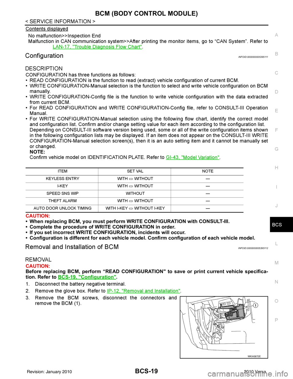
1. Disconnect the battery negative terminal.
2. Remove the glove box. Refer to IP-12, "
Removal and Installation".
3. Remove the BCM screws, disconnect the connectors and remove the BCM (1).
ITEM SET VAL NOTE
KEYLESS ENTRY WITH ⇔ WITHOUT —
I-KEY WITH ⇔ WITHOUT —
SPEED SNS WIP WITHOUT —
THEFT ALARM WITH ⇔ WITHOUT —
AUTO DOOR UNLOCK TIMING WITH I-KEY ⇔ WITHOUT I-KEY —
WKIA5672E
Revision: January 20102010 Versa
Page 531 of 3745
BL-22
< SERVICE INFORMATION >
POWER DOOR LOCK SYSTEM
POWER DOOR LOCK SYSTEM
Component Parts and Harness Connector LocationINFOID:0000000005396553
ALKIA1773ZZ
1. BCM M18, M19, M20
(view with glove box removed) 2. Intelligent Key unit M52
(if equipped) 3. Front door key cylinder switch LH D14
4. Front door switch LH B8, RH B108 5. Front door lock actuator LH D3, RH D114 6. Rear door switch LH B6, RH B116
7. Rear door lock actuator LH D205 RH D305 8. Key switch and ignition knob switch M73
(with A/T and Intelligent Key) 9. Key switch and ignition knob switch
M73 (with M/T and Intelligent Key)
Revision: January 20102010 Versa
Page 567 of 3745
BL-58
< SERVICE INFORMATION >
REMOTE KEYLESS ENTRY SYSTEM
REMOTE KEYLESS ENTRY SYSTEM
Component Parts and Harness Connector LocationINFOID:0000000005396573
System DescriptionINFOID:0000000005396574
INPUTS
Power is supplied at all times
• through 40A fusible link (letter g , located in the fuse and fusible link box)
• to BCM terminal 70
• through 10A fuse [No. 8, located in the fuse block (J/B)]
• to BCM terminal 57.
When the key switch is ON (key is inserted in ignition key cylinder), power is supplied
ALKIA1754ZZ
1. BCM M18, M19, M20
(view with glove box removed) 2. Remote keyless entry receiver M23 3. Horn relay H-1
(front of battery)
4. IPDM E/R E46, E48 5. Front door switch LH B8, RH B108 6. Rear door switch LH B6, RH B116
7. Back door lock assembly (back door switch) D405 (hatchback view with
back door open) 8. Key switch and key lock solenoid
M27 9. Horn E18, E20
Revision: January 20102010 Versa
Page 594 of 3745

REMOTE KEYLESS ENTRY SYSTEMBL-85
< SERVICE INFORMATION >
C
DE
F
G H
J
K L
M A
B
BL
N
O P
• When registering an additional keyfob, the existing ID codes in memory may or may not be erased. If five ID
codes are stored in memory, when an additional code is registered, only the oldest code is erased. If less
than five ID codes are stored in memory, when an additional ID code is registered, the new ID code is added
and no ID codes are erased.
• If you need to activate more than two additional new keyfobs, repeat the procedure “Additional ID code
entry” for each new keyfob.
• Entry of maximum five ID codes is allowed. When mo re than five ID codes are entered, the oldest ID code
will be erased.
• Even if same ID code that is already in the memory is input, the same ID code can be entered. The code is
counted as an additional code.
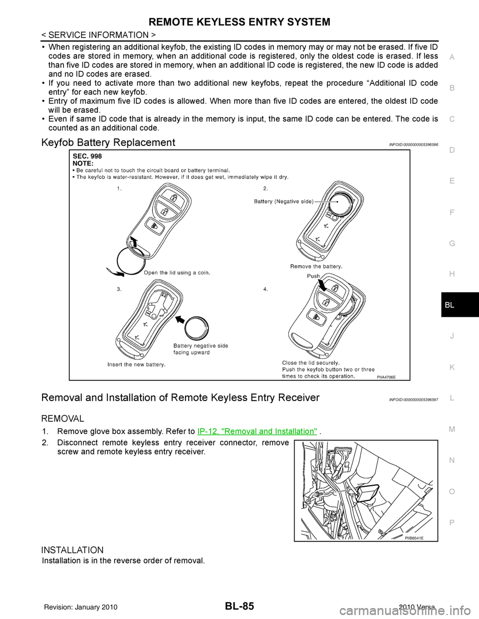
Keyfob Battery ReplacementINFOID:0000000005396596
Removal and Installation of Re mote Keyless Entry ReceiverINFOID:0000000005396597
REMOVAL
1. Remove glove box assembly. Refer to IP-12, "Removal and Installation" .
2. Disconnect remote keyless entry receiver connector, remove screw and remote keyless entry receiver.
INSTALLATION
Installation is in the reverse order of removal.
PIIA4706E
PIIB6541E
Revision: January 20102010 Versa
Page 596 of 3745
INTELLIGENT KEY SYSTEMBL-87
< SERVICE INFORMATION >
C
DE
F
G H
J
K L
M A
B
BL
N
O P
ALKIA1775ZZ
1. Horn E18, E20 2. Horn relay H-1 3. Instrument panel antenna M10
(view with glove box removed)
4. BCM M18, M19, M20 5. Intelligent Key unit M52 6. Combination meter M24
7. Intelligent key "KEY" warning indi- cator 8a.
8b.Intelligent key warning indicator (CVT or
A/T)
Intelligent key warning indicator (M/T) 9. Stop lamp switch E13
Revision: January 20102010 Versa
Page 599 of 3745

BL-90
< SERVICE INFORMATION >
INTELLIGENT KEY SYSTEM
* : Hatchback
** : Sedan
KEY REMINDER FUNCTION
Key reminder functions have the following 2 functions.
CAUTION:
• The above function operates when the Intelligent Key is inside the vehicle. However, there may be
times when the Intelligent Key cannot be detected, an d this function will not operate when the Intelli-
gent Key is on the instrument panel, rear parcel shelf or in the glove box. Also, this system some-
times does not operate if the Intelligent Key is in the door pocket of an open door.
List of Operation Related Parts
Parts marked with × are the parts related to operation
REMOTE KEYLESS ENTRY FUNCTIONS
The Intelligent Key has the same functions as the remote keyless entry system. T herefore, it can be used in
the same manner as the keyfob by operating the door lock/unlock button.
Door lock open function
Intelligent Key
Key switch
Ignition knob switch
Door switch
Back door lock assembly (back door switch)
*
Request switch (driver, passenger, back)
Door lock actuator
Inside key antenna
Outside key antenna
Intelligent Key warning buzzer (front door LH)
Intelligent Key warning buzzer (trunk)
**
Intelligent Key unit
CAN communication system
BCM
Hazard warning lamp
Door lock/unlock function by request switch ××××××××××
Door lock/unlock function by mechanical key ××
Hazard and buzzer reminder function ××××××
Auto door lock function ×××× × ×××
Key reminder functionOperation condition Operation
Door is open to close Right after all doors are closed under the following conditions.
• Intelligent Key is inside the vehicle
• Any door is opened
• All doors are locked by door lock and unlock switch or door
lock knob • All doors unlock operation
• Sound Intelligent Key warn-
ing buzzer for 3 seconds
Key reminder functions
Intelligent Key
Door switch
Unlock sensor
Door lock actuator
Inside key antenna
Intelligent Key warning buzzer(s)
Intelligent Key unit
CAN communication system
BCM
Any door open to close ×××××××××
Revision: January 20102010 Versa
Page 667 of 3745
BL-158
< SERVICE INFORMATION >
INTELLIGENT KEY SYSTEM
Intelligent Key Battery Replacement
INFOID:0000000005396641
INTELLIGENT KEY BATTERY INSPECTION
Check by connecting a resistance (approximately 300 Ω) so that the
current value becomes about 10 mA.
Remote Keyless Entry FunctionINFOID:0000000005396642
Check keyfob function using Remote Keyless Entry Tester J-43241.
Removal and Installation of Intelligent Key UnitINFOID:0000000005396643
REMOVAL
1. Remove glove box assembly. Refer to IP-12, "Removal and Installation".
PIIB5065E
Standard : Approx. 2.5 - 3.0V
OCC0607D
LEL946A
Revision: January 20102010 Versa
Page 681 of 3745

BL-172
< SERVICE INFORMATION >
BACK DOOR LOCK
BACK DOOR LOCK
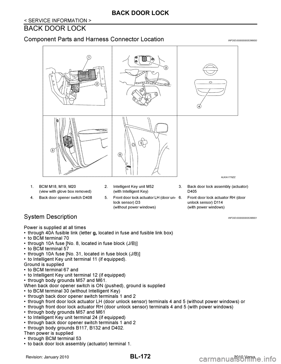
Component Parts and Harness Connector LocationINFOID:0000000005396650
System DescriptionINFOID:0000000005396651
Power is supplied at all times
• through 40A fusible link (letter g, located in fuse and fusible link box)
• to BCM terminal 70
• through 10A fuse [No. 8, located in fuse block (J/B)]
• to BCM terminal 57
• through 10A fuse [No. 31, located in fuse block (J/B)]
• to Intelligent Key unit terminal 11 (if equipped).
Ground is supplied
• to BCM terminal 67 and
• to Intelligent Key unit terminal 12 (if equipped)
• through body grounds M57 and M61.
When back door opener switch is ON (pushed), ground is supplied
• to BCM terminal 30 (without Intelligent Key)
• through back door opener switch terminals 1 and 2
• through front door lock actuator LH (door unlock s ensor) terminals 4 and 5 (without power windows) or
• through front door lock actuator RH (door unlock sensor) terminals 4 and 5 (with power windows)
• through body grounds M57 and M61
• to Intelligent Key unit terminal 24 (if equipped)
• through back door opener switch terminals 1 and 2
• through body grounds B117, B132 and D402.
Then power is supplied
• through BCM terminal 53
• to back door lock assembly (actuator) terminal 1.
ALKIA1776ZZ
1. BCM M18, M19, M20
(view with glove box removed) 2. Intelligent Key unit M52
(with Intelligent Key) 3. Back door lock assembly (actuator)
D405
4. Back door opener switch D408 5. Front door lock actuator LH (door un- lock sensor) D3
(without power windows)6. Front door lock actuator RH (door
unlock sensor) D114
(with power windows)
Revision: January 20102010 Versa