Page 3686 of 3745
TIRE PRESSURE MONITORING SYSTEMWT-9
< SERVICE INFORMATION >
C
DF
G H
I
J
K L
M A
B
WT
N
O P
TIRE PRESSURE MO NITORING SYSTEM
System ComponentINFOID:0000000005397093
System DescriptionINFOID:0000000005397094
BODY CONTROL MODULE (BCM)
The BCM is shown with the glove box removed. The BCM reads the
air pressure signal received by the remote keyless entry receiver,
and controls the low tire pressure warning lamp as shown below. It
also has a self-diagnosis function to detect a system malfunction.
TRANSMITTER
WEIA0185E
1. BCM
M18, M20 2. Transmitters 3. Tire pressure warning check connector
M39
4. Combination meter M24 5. Remote keyless entry receiver
M23
Condition Low tire pressure warning lamp
System normal On for 1 second after ignition ON
Tire less than 193 kPa (2.0 kg/cm
2 , 28 psi)
[Flat tire] ON
Tire pressure monitoring system malfunc-
tion After key ON, flashes once per sec-
ond for 1 minute, then stays ON
WEIA0187E
Revision: January 20102010 Versa
Page 3687 of 3745

WT-10
< SERVICE INFORMATION >
TIRE PRESSURE MONITORING SYSTEM
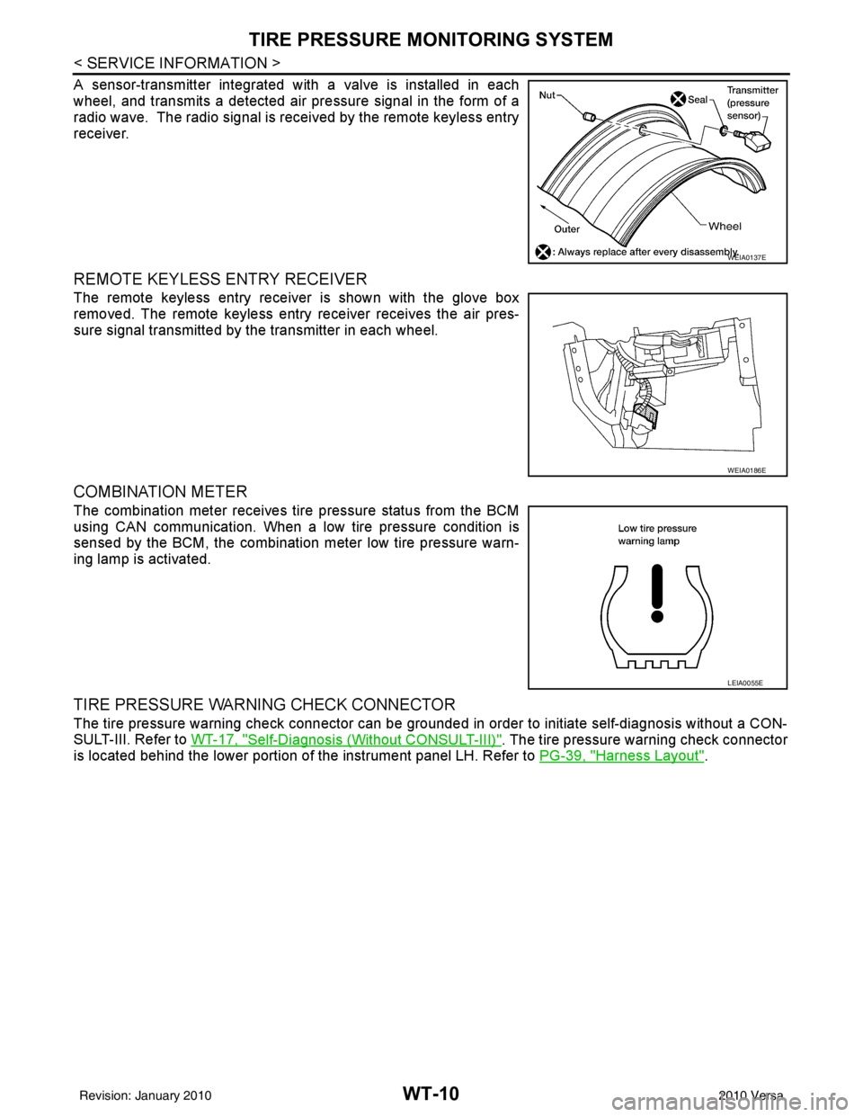
A sensor-transmitter integrated with a valve is installed in each
wheel, and transmits a detected air pressure signal in the form of a
radio wave. The radio signal is received by the remote keyless entry
receiver.
REMOTE KEYLESS ENTRY RECEIVER
The remote keyless entry receiver is shown with the glove box
removed. The remote keyless entry receiver receives the air pres-
sure signal transmitted by the transmitter in each wheel.
COMBINATION METER
The combination meter receives tire pressure status from the BCM
using CAN communication. When a low tire pressure condition is
sensed by the BCM, the combination meter low tire pressure warn-
ing lamp is activated.
TIRE PRESSURE WARNING CHECK CONNECTOR
The tire pressure warning check connector can be grounded in order to initiate self-diagnosis without a CON-
SULT-III. Refer to WT-17, "
Self-Diagnosis (Without CONSULT-III)". The tire pressure warning check connector
is located behind the lower portion of the instrument panel LH. Refer to PG-39, "
Harness Layout".
WEIA0137E
WEIA0186E
LEIA0055E
Revision: January 20102010 Versa
Page 3710 of 3745

FRONT WIPER AND WASHER SYSTEMWW-5
< SERVICE INFORMATION >
C
DE
F
G H
I
J
L
M A
B
WW
N
O P
FRONT WIPER AND WASHER SYSTEM
Component Parts and Har ness Connector LocationINFOID:0000000005395054
System DescriptionINFOID:0000000005395055
• Front wiper relays (front wiper relay, front wiper high relay) are located in the IPDM E/R (intelligent power
distribution module engine room).
• Wiper switch (combination switch) is composed of a combination of 5 output terminals and 5 input terminals.
Terminal combination status is read by BCM (body control module) when switch is turned ON.
• BCM controls front wiper LO, HI, and INT (intermittent) operation.
• IPDM E/R operates wiper motor accordi ng to CAN communication signals from BCM.
OUTLINE
Power is supplied at all times• to ignition relay, located in IPDM E/R, from battery directly,
• through 40A fusible link (letter g, located in fuse and fusible link box)
• to BCM terminal 70,
• through 30A fuse (No. 39, located in IPDM E/R)
• to front wiper relay located in IPDM E/R
• through 15A fuse (No. 52, located in IPDM E/R), and
• through 20A fuse (No. 53, located in IPDM E/R)
• to CPU located in IPDM E/R.
When ignition switch is in ON or START position, power is supplied • through ignition relay (located in IPDM E/R)
• to front wiper relay (located in IPDM E/R), and
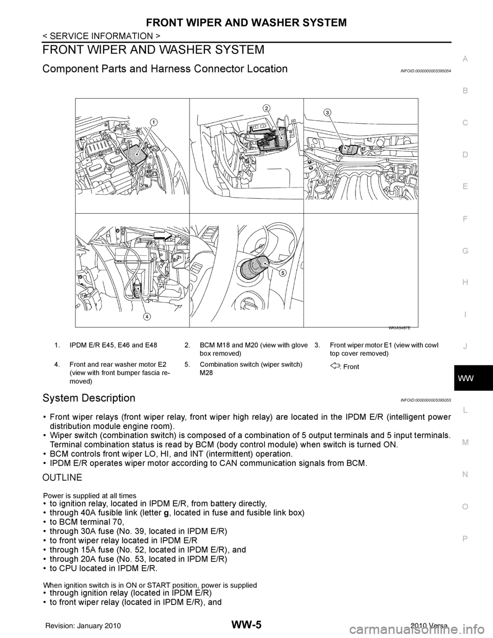
1. IPDM E/R E45, E46 and E48 2. BCM M18 and M20 (view with glove
box removed)3. Front wiper motor E1
(view with cowl
top cover removed)
4. Front and rear washer motor E2 (view with front bumper fascia re-
moved) 5. Combination switch (wiper switch)
M28 : Front
WKIA5467E
Revision: January 20102010 Versa
Page 3731 of 3745

WW-26
< SERVICE INFORMATION >
REAR WIPER AND WASHER SYSTEM
REAR WIPER AND WASHER SYSTEM
Component Parts and Harness Connector LocationINFOID:0000000005395084
System DescriptionINFOID:0000000005395085
• The wiper switch (combination switch) is composed of a combination of 5 output terminals and 5 input termi-
nals. Terminal combination status is read by the BC M (body control module) when switch is turned ON.
• The BCM controls rear wiper ON and INT (intermittent) operation.
Power is supplied at all times
• through 40A fusible link (letter g , located in fuse and fusible link box)
• to BCM terminal 70.
With the ignition switch in ON or START position, power is supplied
• through 15A fuse [No. 4, located in the fuse block (J/B)]
• to combination switch terminal 2
• through 10A fuse [No. 6, located in the fuse block (J/B)]
• to BCM terminal 38.
Ground is supplied
• to BCM terminal 67, and
• to combination switch terminal 12
• through grounds M57 and M61.
REAR WIPER OPERATION
When the ignition switch is in the ON or START position, and the rear wiper switch is in the ON position, the
BCM detects a rear wiper ON request through the combination switch (wiper switch) reading function and con-
trols the rear wiper motor as follows.
Power is supplied
• through BCM terminal 55
• to rear wiper motor terminal 1.
Ground is supplied
WKIA5507E
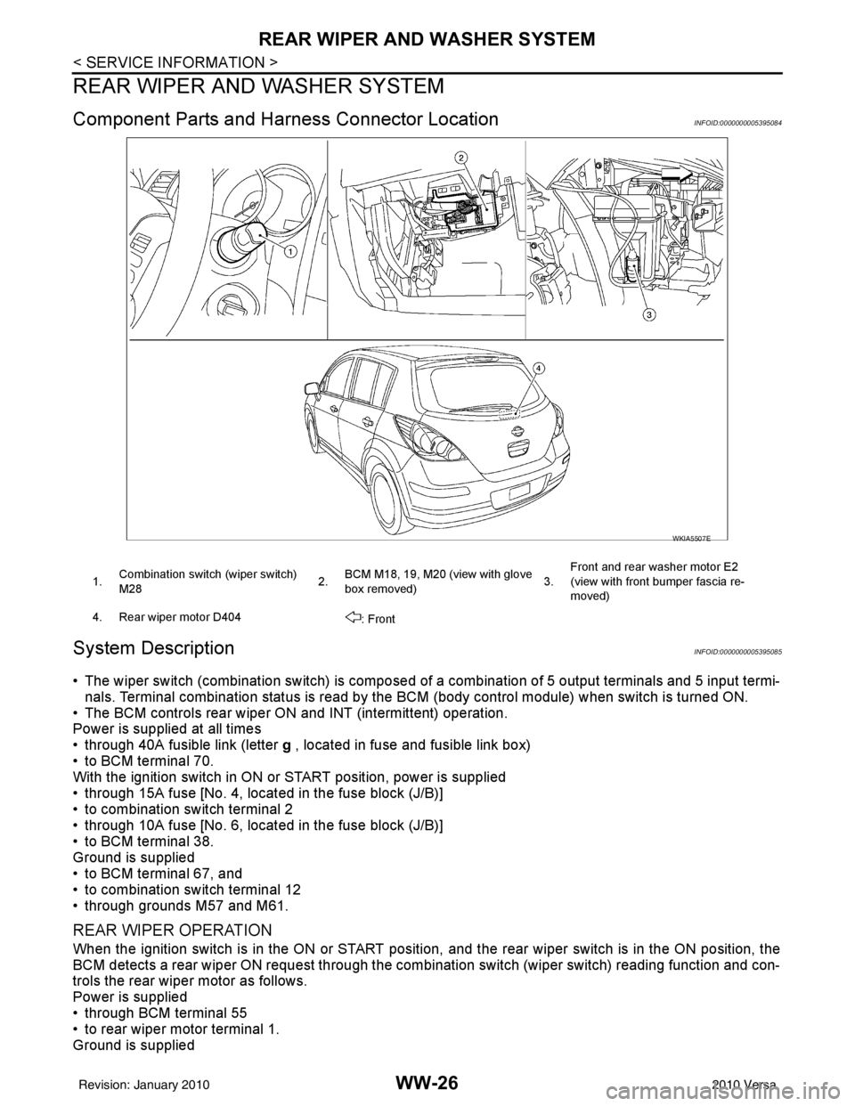
1. Combination switch (wiper switch)
M28 2.BCM M18, 19, M20 (view with glove
box removed) 3.Front and rear washer motor E2
(view with front bumper fascia re-
moved)
4. Rear wiper motor D404 : Front
Revision: January 20102010 Versa