2010 NISSAN TIIDA oil tank
[x] Cancel search: oil tankPage 864 of 3745
BR-16
< SERVICE INFORMATION >
BRAKE MASTER CYLINDER
INSTALLATION
CAUTION:
• Refill using recommended brake fluid. Refer to MA-14, "
Fluids and Lubricants".
• Never reuse drained brake fluid.
• Check if the rod of primary piston has dust or scratches.
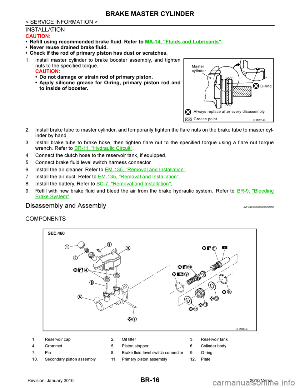
1. Install master cylinder to brake booster assembly, and tighten nuts to the specified torque.
CAUTION:
• Do not damage or strain rod of primary piston.
• Apply silicone grease for O-ring, primary piston rod andto inside of booster.
2. Install brake tube to master cylinder, and temporarily tighten the flare nuts on the brake tube to master cyl- inder by hand.
3. Install brake tube to brake hose, then tighten flare nut to the specified torque using a flare nut torque
wrench. Refer to BR-11, "
Hydraulic Circuit".
4. Connect the clutch hose to the reservoir tank, if equipped.
5. Connect brake fluid level switch harness connector.
6. Install the air cleaner. Refer to EM-135, "
Removal and Installation".
7. Install the air duct. Refer to EM-135, "
Removal and Installation".
8. Install the battery. Refer to SC-7, "
Removal and Installation".
9. Refill with new brake fluid and bleed the air from the brake hydraulic system. Refer toBR-9, "
Bleeding
Brake System".
Disassembly and AssemblyINFOID:0000000005396991
COMPONENTS
SFIA2614E
1. Reservoir cap2. Oil filter 3. Reservoir tank
4. Grommet 5. Piston stopper 6. Cylinder body
7. Pin 8. Brake fluid level switch connector 9. O-ring
10. Secondary piston assembly 11. Primary piston assembly 12. Plate
SFIA3094E
Revision: January 20102010 Versa
Page 1006 of 3745
![NISSAN TIIDA 2010 Service Repair Manual CO-24
< ON-VEHICLE REPAIR >[HR16DE]
THERMOSTAT
• Install thermostat (2) into the cylinder block (1) with jiggle valve (A)
facing upwards.
Water Inlet.
After installation, fix water inlet clip (A) o](/manual-img/5/57397/w960_57397-1005.png "NISSAN TIIDA 2010 Service Repair Manual CO-24
< ON-VEHICLE REPAIR >[HR16DE]
THERMOSTAT
• Install thermostat (2) into the cylinder block (1) with jiggle valve (A)
facing upwards.
Water Inlet.
After installation, fix water inlet clip (A) o")
CO-24
< ON-VEHICLE REPAIR >[HR16DE]
THERMOSTAT
• Install thermostat (2) into the cylinder block (1) with jiggle valve (A)
facing upwards.
Water Inlet.
After installation, fix water inlet clip (A) on the oil level gauge guide
(1) positioned (B) as shown.
InspectionINFOID:0000000005398197
INSPECTION AFTER REMOVAL
WARNING:
Use a protector to prevent a burn during the work.
Thermostat
• Place a thread (A) so that it is caught in the valves of thermostat(1). Immerse fully in a container (B) filled with water. Heat while
stirring.
• The valve opening temperature is the temperature at which the valve opens and falls from the thread.
• Continue heating. Check the full-open valve lift amount.
• After checking the full-open valve lift amount, lower the water tem- perature and check the valve closing temperature.
• If out of the standard, replace thermostat.
INSPECTION AFTER INSTALLATION
• Check that the reservoir tank cap is tightened.
• Check for leaks of engine coolant using suitable tools. Refer to CO-12, "
Inspection".
• Start and warm up the engine. Visually make sure that there is no leaks of engine coolant.
PBIC3812E
PBIC3755E
Standard : Refer to CO-27, "Thermostat".
PBIC3314J
Revision: January 20102010 Versa
Page 1368 of 3745
![NISSAN TIIDA 2010 Service Repair Manual ON BOARD DIAGNOSTIC (OBD) SYSTEMEC-103
< FUNCTION DIAGNOSIS > [HR16DE]
C
D
E
F
G H
I
J
K L
M A
EC
NP
O
ACTIVE TEST MODE
Test Item
*: Leaving cooling fan OFF with CONSULT-III while engine is running ma](/manual-img/5/57397/w960_57397-1367.png "NISSAN TIIDA 2010 Service Repair Manual ON BOARD DIAGNOSTIC (OBD) SYSTEMEC-103
< FUNCTION DIAGNOSIS > [HR16DE]
C
D
E
F
G H
I
J
K L
M A
EC
NP
O
ACTIVE TEST MODE
Test Item
*: Leaving cooling fan OFF with CONSULT-III while engine is running ma")
ON BOARD DIAGNOSTIC (OBD) SYSTEMEC-103
< FUNCTION DIAGNOSIS > [HR16DE]
C
D
E
F
G H
I
J
K L
M A
EC
NP
O
ACTIVE TEST MODE
Test Item
*: Leaving cooling fan OFF with CONSULT-III while engine is running may cause the engine to overheat.
DTC & SRT CONFIRMATION MODE
SRT STATUS Mode
For details, refer to
EC-84, "Diagnosis Description".
PERMANENT DTC STATUS Mode
For details, refer to EC-84, "Diagnosis Description".
NOTE:
This mode is not used in regions that permanent DTCs are not regulated by law.
TEST ITEMCONDITION JUDGMENTCHECK ITEM (REMEDY)
FUEL INJECTION • Engine: Return to the original
trouble condition
• Change the amount of fuel injec-
tion using CONSULT-III. If trouble symptom disappears, see
CHECK ITEM.
• Harness and connectors
• Fuel injector
• Air fuel ratio (A/F) sensor 1
IGNITION TIMING • Engine: Return to the original
trouble condition
• Timing light: Set
• Retard the ignition timing using
CONSULT-III. If trouble symptom disappears, see
CHECK ITEM.
• Perform Idle Air Volume Learning.
POWER BALANCE • Engine: After warming up, idle
the engine.
• A/C switch OFF
• Selector lever: P or N position (A/ T), Neutral position (M/T)
• Cut off each fuel injector signal one at a time using CONSULT-
III. Engine runs rough or dies.
• Harness and connectors
• Compression
• Fuel injector
• Power transistor
• Spark plug
• Ignition coil
COOLING FAN* • Ignition switch: ON
• Turn the cooling fan “LOW”, “HI”
and “OFF” using CONSULT-III. Cooling fan moves and stops. • Harness and connectors
• IPDM E/R (Cooling fan relay)
• Cooling fan motor
ENG COOLANT
TEMP • Engine: Return to the original
trouble condition
• Change the engine coolant tem- perature using CONSULT-III. If trouble symptom disappears, see
CHECK ITEM.
• Harness and connectors
• Engine coolant temperature sen-
sor
• Fuel injector
FUEL PUMP RELAY • Ignition switch: ON (Engine
stopped)
• Turn the fuel pump relay “ON” and “OFF” using CONSULT-III
and listen to operating sound. Fuel pump relay makes the operat-
ing sound.
• Harness and connectors
•Fuel pump relay
PURG VOL CONT/V • Engine: After warming up, run
engine at 1,500 rpm.
• Change the EVAP canister purge volume control solenoid
valve opening percent using
CONSULT-III. Engine speed changes according
to the opening percent.
• Harness and connectors
• Solenoid valve
FUEL/T TEMP SEN • Change the fuel tank temperature using CONSULT-III.
VENT CONTROL/V • Ignition switch: ON (Engine
stopped)
• Turn solenoid valve “ON” and
“OFF” using the CONSULT-III
and listen to operating sound. Solenoid valve makes an operating
sound.
• Harness and connectors
• Solenoid valve
V/T ASSIGN ANGLE • Engine: Return to the original
trouble condition
• Change intake valve timing us- ing CONSULT-III. If trouble symptom disappears, see
CHECK ITEM.
• Harness and connectors
• Intake valve timing control sole-
noid valve
Revision: January 20102010 Versa
Page 1627 of 3745
![NISSAN TIIDA 2010 Service Repair Manual EC-362
< COMPONENT DIAGNOSIS >[HR16DE]
P1217 ENGINE OVER TEMPERATURE
P1217 ENGINE OVER TEMPERATURE
DTC LogicINFOID:0000000005398526
DTC DETECTION LOGIC
NOTE:
•
If DTC P1217 is displayed with DTC UX](/manual-img/5/57397/w960_57397-1626.png "NISSAN TIIDA 2010 Service Repair Manual EC-362
< COMPONENT DIAGNOSIS >[HR16DE]
P1217 ENGINE OVER TEMPERATURE
P1217 ENGINE OVER TEMPERATURE
DTC LogicINFOID:0000000005398526
DTC DETECTION LOGIC
NOTE:
•
If DTC P1217 is displayed with DTC UX")
EC-362
< COMPONENT DIAGNOSIS >[HR16DE]
P1217 ENGINE OVER TEMPERATURE
P1217 ENGINE OVER TEMPERATURE
DTC LogicINFOID:0000000005398526
DTC DETECTION LOGIC
NOTE:
•
If DTC P1217 is displayed with DTC UXXXX, first perform the trouble diagnosis for DTC UXXXX.
• If DTC P1217 is displayed with DTC P0607, first perform the trouble diagno sis for DTC P0607. Refer
to EC-351, "
DTC Logic".
If the cooling fan or another component in the cooling system malfunctions, engine coolant temperature will
rise.
When the engine coolant temperature reaches an abnorma lly high temperature condition, a malfunction is
indicated.
CAUTION:
When a malfunction is indicated, be su re to replace the coolant. Refer to CO-12, "
Changing Engine
Coolant". Also, replace the engine oil. Refer to LU-8, "Draining" and LU-8, "Refilling".
1. Fill radiator with coolant up to specified level with a filling speed of 2 liters per minute. Be sure to use coolant with the proper mixture ratio. Refer to MA-15, "
Anti-freeze Coolant Mixture Ratio".
2. After refilling coolant, run engine to en sure that no water-flow noise is emitted.
DTC CONFIRMATION PROCEDURE
1.PERFORM COMPONENT FUNCTION CHECK
Perform component function check. Refer to EC-362, "
Component Function Check".
NOTE:
Use component function check to check the overall function of the cooling fan. During this check, a DTC might
not be confirmed.
Is the inspection result normal?
YES >> INSPECTION END
NO >> Go to EC-363, "
Diagnosis Procedure".
Component Function CheckINFOID:0000000005398527
1.PERFORM COMPONENT FUNCTION CHECK-I
WARNING:
Never remove the radiator cap when the engine is hot. Serious burns could be caused by high pres-
sure fluid escaping from the radiator.
Wrap a thick cloth around cap. Carefully remove the cap by turning it a quarter turn to allow built-up
pressure to escape. Then turn the cap all the way off.
DTC No. Trouble diagnosis name DTC detecting conditionPossible cause
P1217 Engine over temperature
(Overheat) • Cooling fan does not operate properly (Over-
heat).
• Cooling fan system does not operate properly (Overheat).
• Engine coolant was not added to the system using the proper filling method.
• Engine coolant is not within the specified range. • Harness or connectors
(The cooling fan circuit is open or
shorted.)
• IPDM E/R (Cooling fan relay-1)
• Cooling fan relays-2 and -3
• Cooling fan motor
•Radiator hose
•Radiator
•Radiator cap
• Reservoir tank
• Water pump
•Thermostat
• Water control valve
Revision: January 20102010 Versa
Page 1751 of 3745
![NISSAN TIIDA 2010 Service Repair Manual EC-486
< SYMPTOM DIAGNOSIS >[HR16DE]
ENGINE CONTROL SYSTEM SYMPTOMS
SYMPTOM
Reference page
HARD/NO START/RESTART (EXCP. HA)
ENGINE STALL
HESITATION/SURGING/FLAT SPOT
SPARK KNOCK/DETONATION
LACK OF POW](/manual-img/5/57397/w960_57397-1750.png "NISSAN TIIDA 2010 Service Repair Manual EC-486
< SYMPTOM DIAGNOSIS >[HR16DE]
ENGINE CONTROL SYSTEM SYMPTOMS
SYMPTOM
Reference page
HARD/NO START/RESTART (EXCP. HA)
ENGINE STALL
HESITATION/SURGING/FLAT SPOT
SPARK KNOCK/DETONATION
LACK OF POW")
EC-486
< SYMPTOM DIAGNOSIS >[HR16DE]
ENGINE CONTROL SYSTEM SYMPTOMS
SYMPTOM
Reference page
HARD/NO START/RESTART (EXCP. HA)
ENGINE STALL
HESITATION/SURGING/FLAT SPOT
SPARK KNOCK/DETONATION
LACK OF POWER/POOR ACCELERATION
HIGH IDLE/LOW IDLE
ROUGH IDLE/HUNTING
IDLING VIBRATION
SLOW/NO RETURN TO IDLE
OVERHEATS/WATER TEMPERATURE HIGH
EXCESSIVE FUEL CONSUMPTION
EXCESSIVE OIL CONSUMPTION
BATTERY DEAD (UNDER CHARGE)
Warranty symptom code A
A AB AC AD AE AF AG AH AJ AK AL AM HA
Fuel Fuel tank 5
5 FL-12
Fuel piping
5 5 5 5 5 5FL-5
Va p o r l o c k —
Valve deposit 5 555 55 5 —
Poor fuel (Heavy weight gas-
oline, Low octane) —
Air Air duct
55555 5 EM-26
Air cleaner
Air leakage from air duct
(Mass air flow sensor — elec-
tric throttle control actuator)
555 5
Electric throttle control actua-
tor
EM-28
Air leakage from intake mani-
fold/Collector/Gasket
Cranking Battery 111111
11
SC-5
Generator circuit
SC-21
Starter circuit3 SC-9
Signal plate6 EM-90
PNP switch (M/T)
Transmission range switch
(A/T)4
MT-13 (M/T)
AT- 9 4
(A/T)
Engine Cylinder head 55555 55 5 EM-73
Cylinder head gasket 4 3
Cylinder block
66666 66 64
EM-90
Piston
Piston ring
Connecting rod
Bearing
Crankshaft
Revision: January 20102010 Versa
Page 1859 of 3745
![NISSAN TIIDA 2010 Service Repair Manual EC-594
< SERVICE INFORMATION >[MR18DE]
TROUBLE DIAGNOSIS
SYMPTOM
Reference
HARD/NO START/RESTART (EXCP. HA)
ENGINE STALL
HESITATION/SURGING/FLAT SPOT
SPARK KNOCK/DETONATION
LACK OF POWER/POOR ACCELERA](/manual-img/5/57397/w960_57397-1858.png "NISSAN TIIDA 2010 Service Repair Manual EC-594
< SERVICE INFORMATION >[MR18DE]
TROUBLE DIAGNOSIS
SYMPTOM
Reference
HARD/NO START/RESTART (EXCP. HA)
ENGINE STALL
HESITATION/SURGING/FLAT SPOT
SPARK KNOCK/DETONATION
LACK OF POWER/POOR ACCELERA")
EC-594
< SERVICE INFORMATION >[MR18DE]
TROUBLE DIAGNOSIS
SYMPTOM
Reference
HARD/NO START/RESTART (EXCP. HA)
ENGINE STALL
HESITATION/SURGING/FLAT SPOT
SPARK KNOCK/DETONATION
LACK OF POWER/POOR ACCELERATION
HIGH IDLE/LOW IDLE
ROUGH IDLE/HUNTING
IDLING VIBRATION
SLOW/NO RETURN TO IDLE
OVERHEATS/WATER TEMPERATURE HIGH
EXCESSIVE FUEL CONSUMPTION
EXCESSIVE OIL CONSUMPTION
BATTERY DEAD (UNDER CHARGE)
Warranty symptom code AA AB AC AD AE AF AG AH AJ AK AL AM HA
Fuel Fuel tank 5
5 FL-12
Fuel piping
5 5 5 5 55FL-5
Va p o r l o c k —
Valve deposit 5 555 55 5—
Poor fuel (Heavy weight gasoline,
Low octane) —
Air Air duct
55555 5 EM-135
Air cleaner
EM-135
Air leakage from air duct
(Mass air flow sensor — electric
throttle control actuator)
5555 EM-135
Electric throttle control actuator
EM-137
Air leakage from intake manifold/
Collector/GasketEM-137
Cranking Battery
111111
11
SC-7
Generator circuit
SC-22
Starter circuit3 SC-16
Signal plate6 EM-196
Park/neutral position (PNP)
switch (M/T)
Transmission range switch (A/T
or CVT)4
MT-57,
AT- 9 4
,
CVT-70
Engine Cylinder head 55555 55 5 EM-182
Cylinder head gasket 4 3
Cylinder block
66666 66 64
EM-196
Piston
Piston ring
Connecting rod
Bearing
Crankshaft
Revision: January 20102010 Versa
Page 1863 of 3745
![NISSAN TIIDA 2010 Service Repair Manual EC-598
< SERVICE INFORMATION >[MR18DE]
TROUBLE DIAGNOSIS
: Vehicle front
1. Intake valve timing control solenoid valve 2. Knock sensor
3. IPDM E/R
4. Fuel pump fuse (15 A) 5. Fuel level sensor unit](/manual-img/5/57397/w960_57397-1862.png "NISSAN TIIDA 2010 Service Repair Manual EC-598
< SERVICE INFORMATION >[MR18DE]
TROUBLE DIAGNOSIS
: Vehicle front
1. Intake valve timing control solenoid valve 2. Knock sensor
3. IPDM E/R
4. Fuel pump fuse (15 A) 5. Fuel level sensor unit")
EC-598
< SERVICE INFORMATION >[MR18DE]
TROUBLE DIAGNOSIS
: Vehicle front
1. Intake valve timing control solenoid valve 2. Knock sensor
3. IPDM E/R
4. Fuel pump fuse (15 A) 5. Fuel level sensor unit and fuel pump
harness connector (view with in-
spection hole cover removed) 6. Fuel level sensor unit and fuel pump
7. Fuel pressure regulator 8. Fuel level sensor9. Fuel tank temperature sensor
10. Ignition coil (with power transistor) and spark plug 11. Fuel injector
BBIA0725E
Revision: January 20102010 Versa
Page 1882 of 3745
![NISSAN TIIDA 2010 Service Repair Manual TROUBLE DIAGNOSISEC-617
< SERVICE INFORMATION > [MR18DE]
C
D
E
F
G H
I
J
K L
M A
EC
NP
O
NOTE:
Any monitored item that does not match the vehicle being diagnosed is deleted from the display automatica](/manual-img/5/57397/w960_57397-1881.png "NISSAN TIIDA 2010 Service Repair Manual TROUBLE DIAGNOSISEC-617
< SERVICE INFORMATION > [MR18DE]
C
D
E
F
G H
I
J
K L
M A
EC
NP
O
NOTE:
Any monitored item that does not match the vehicle being diagnosed is deleted from the display automatica")
TROUBLE DIAGNOSISEC-617
< SERVICE INFORMATION > [MR18DE]
C
D
E
F
G H
I
J
K L
M A
EC
NP
O
NOTE:
Any monitored item that does not match the vehicle being diagnosed is deleted from the display automatically.
ACTIVE TEST MODE
Test Item
HO2 S2 DIAG2 (B1)
[INCMP/CMPLT]
• Indicates DTC P0139 self-diagnosis (slow response) condi-
tion.
INCMP: Self-diagnosis is incomplete.
CMPLT: Self-diagnosis is complete.
A/F SEN1
DIAG1(B1)
[INCMP/CMPLT] • Indicates DTC P015A or P015B self-diagnosis condition.
INCMP: Self-diagnosis is incomplete.
CMPLT: Self-diagnosis is complete.
A/F SEN1
DIAG2(B1)
[INCMP/CMPLT] • Indicates DTC P014C or P014D self-diagnosis condition.
INCMP: Self-diagnosis is incomplete.
CMPLT: Self-diagnosis is complete.
A/F SEN1
DIAG3(B1)
[ABSNT/PRSNT] • Indicates DTC P014C, P014D, P015A or P015B self-diagno-
sis condition.
ABSNT: The vehicle condition is not within the diagnosis
range.
PRSNT: The vehicle condition is within the diagnosis range.
Monitored item [Unit]
Description Remarks
Test itemCondition JudgmentCheck item (Remedy)
FUEL INJEC-
TION • Engine: Return to the original
trouble condition
• Change the amount of fuel injec- tion using CONSULT-III. If trouble symptom disappears, see
CHECK ITEM.
• Harness and connectors
• Fuel injector
• Air fuel ratio (A/F) sensor 1
IGNITION TIM-
ING • Engine: Return to the original
trouble condition
• Timing light: Set
• Retard the ignition timing using CONSULT-III. If trouble symptom disappears, see
CHECK ITEM.
• Perform Idle Air Volume Learning.
POWER BAL-
ANCE • Engine: After warming up, idle the
engine.
• A/C switch OFF
• Shift lever: P or N (A/T, CVT), Neutral (M/T)
• Cut off each fuel injector signal one at a time using CONSULT-III. Engine runs rough or dies.
• Harness and connectors
• Compression
• Fuel injector
• Power transistor
•Spark plug
• Ignition coil
COOLING FAN* • Ignition switch: ON
• Turn the cooling fan “LOW”, “HI”
and “OFF” with CONSULT-III. Cooling fan moves and stops.
• Harness and connectors
• Cooling fan relay
• Cooling fan motor
ENG COOLANT
TEMP • Engine: Return to the original
trouble condition
• Change the engine coolant tem-
perature using CONSULT-III. If trouble symptom disappears, see
CHECK ITEM. • Harness and connectors
• Engine coolant temperature sen-
sor
• Fuel injector
FUEL PUMP RE-
LAY • Ignition switch: ON
(Engine stopped)
• Turn the fuel pump relay ON and
OFF using CONSULT-III and lis-
ten to operating sound. Fuel pump relay makes the operat-
ing sound.
• Harness and connectors
• Fuel pump relay
PURG VOL
CONT/V • Engine: After warming up, run en-
gine at 1,500 rpm.
• Change the EVAP canister purge volume control solenoid valve
opening percent using CON-
SULT-III. Engine speed changes according to
the opening percent.
• Harness and connectors
• EVAP canister purge volume con-
trol solenoid valve
FUEL/T TEMP
SEN • Change the fuel tank temperature using CONSULT-III.
Revision: January 20102010 Versa