2010 NISSAN TIIDA Combination switch
[x] Cancel search: Combination switchPage 26 of 3745

PRECAUTIONSAT-9
< SERVICE INFORMATION >
DE
F
G H
I
J
K L
M A
B
AT
N
O P
• Gaskets, seals and O-rings should be replaced any time the A/T is disassembled.
• It is very important to perform func tional tests whenever they are indicated.
• The valve body contains precision parts and requires extreme care when parts are removed and serviced.
Place disassembled valve body parts in order for easier and proper assembly. Care will also prevent springs
and small parts from becoming scattered or lost.
• Properly installed valves, sleeves, plugs, etc. will slide along bores in valve body under their own weight.
• Before assembly, apply a coat of recommended ATF to all parts. Apply petroleum jelly to protect O-rings and seals, or hold bearings and washers in pl ace during assembly. Do not use grease.
• Extreme care should be taken to avoid damage to O-rings, seals and gaskets when assembling.
• Clean or replace ATF cooler if excessive foreign material is found in oil pan or clogging strainer. Refer to AT-
18, "A/T Fluid Cooler Cleaning".
• After overhaul, refill the A/T with new ATF.
• When the A/T drain plug is removed, only some of the fluid is drained. Old A/T fluid will remain in torque con- verter and ATF cooling system.
Always follow the procedures under “Changing A/T Fluid” in the AT section when changing A/T fluid. Refer to
AT-17, "
Changing A/T Fluid", AT-17, "Checking A/T Fluid".
Service Notice or PrecautionINFOID:0000000005397213
ATF COOLER SERVICE
If A/T fluid contains frictional material (clutches, bands, etc.), or if an A/T is repaired, overhauled, or replaced,
inspect and clean the A/T oil cooler mounted in the radiator or replace the radiator. Flush cooler lines using
cleaning solvent and compressed air after repair. Check Service Bulletins for latest A/T oil cooler cleaning pro-
cedure. For radiator replacement, refer to CO-17, "
Removal and Installation" (HR16DE engine models), CO-
41, "Removal and Installation" (MR18DE engine models).
TORQUE CONVERTER SERVICE
The torque converter should be replaced under any of the following conditions:
• External leaks in the hub weld area.
• Converter hub is scored or damaged.
• Converter pilot is broken, damaged or fits poorly into crankshaft.
• Steel particles are found after flushing the cooler and cooler lines.
• Pump is damaged or steel particles are found in the converter.
• Vehicle has TCC shudder and/or no TCC apply. Replace only after all hydraulic and electrical diagnoses
have been made. (Converter clutch material may be glazed.)
• Converter is contaminated with engi ne coolant containing antifreeze.
• Internal malfunction of stator roller clutch.
• Heavy clutch debris due to overheating (blue converter).
• Steel particles or clutch lining material found in flui d filter or on magnet when no internal parts in unit are
worn or damaged — indicates that lining material came from converter.
The torque converter should not be replaced if:
• The fluid has an odor, is discolored, and there is no evidence of metal or clutch facing particles.
• The threads in one or more of the converter bolt holes are damaged.
• A/T malfunction did not display evidence of damaged or worn internal parts, steel particles or clutch plate lin-
ing material in unit and inside the fluid filter.
• Vehicle has been exposed to high mileage (only). The e xception may be where the torque converter clutch
dampener plate lining has seen excess wear by vehicles operated in heavy and/or constant traffic, such as
taxi, delivery or police use.
OBD-II SELF-DIAGNOSIS
• A/T self-diagnosis is performed by the TCM in combination with the ECM. The results can be read through the blinking pattern of the OD OFF indicator lamp or the malfunction indicator lamp (MIL). Refer to the table
on AT-82, "
Diagnosis Procedure without CONSULT-III" for the indicator used to display each self-diagnostic
result.
• The self-diagnostic results indicated by the MIL are automatically stored in both the ECM and TCM memo- ries.
Always perform the procedure “HOW TO ERASE DTC” on AT-39, "
OBD-II Diagnostic Trouble Code
(DTC)" to complete the repair and avoid unnecessary blinking of the MIL.
• The following self-diagnostic items can be detected us ing ECM self-diagnostic results mode* only when the
OD OFF indicator lamp does not indicate any malfunctions.
- Transmission range switch
- A/T 1GR, 2GR, 3GR, or 4GR function
Revision: January 20102010 Versa
Page 54 of 3745

A/T CONTROL SYSTEMAT-37
< SERVICE INFORMATION >
DE
F
G H
I
J
K L
M A
B
AT
N
O P
Control ValveINFOID:0000000005397228
FUNCTION OF CONTROL VALVES
Centrifugal Cancel MechanismINFOID:0000000005397229
FUNCTION
The centrifugal cancel mechanism is a mechanism to c ancel the centrifugal hydraulic pressure instead of the
conventional check balls. It cancels the centrifugal hy draulic pressure which is generated as high clutch drum
rotates, and it allows for preventing high clutch from dragging and for providing stable high clutch piston press-
ing force in all revolution speeds.
STRUCTURE/OPERATION
Valve name Function
Pressure regulator valve, plug and sleeve
plug Regulates oil discharged from the oil pump to provide optimum line pressure for all driving
conditions.
Pressure modifier valve and sleeve Used as a signal supplementary valve to the pressure regulator valve. Regulates pres- sure-modifier pressure (signal pressure) which controls optimum line pressure for all driv-
ing conditions.
Pilot valve Regulates line pressure to maintain a constant pilot pressure level which controls lock-up
mechanism, overrun clutch, shift timing.
Accumulator control valve Regulates accumulator back-pressure to pressure suited to driving conditions.
Manual valve Directs line pressure to oil circuits corresponding to select positions.
Hydraulic pressure drains when the shift lever is in Neutral.
Shift valve A Simultaneously switches three oil circuits using output pressure of shift solenoid valve A
to meet driving conditions (vehicle speed, throttle opening, etc.).
Provides automatic downshifting and upshifting (1GR → 2GR → 3GR → 4GR/4GR →
3GR → 2GR → 1GR) in combination with shift valve B.
Shift valve B Simultaneously switches two oil circuits using output pressure of shift solenoid valve B in
relation to driving conditions (vehicle speed, throttle opening, etc.).
Provides automatic downshifting and upshifting (1GR → 2GR → 3GR → 4GR/4GR →
3GR → 2GR → 1GR) in combination with shift valve A.
Overrun clutch control valve Switches hydraulic circuits to prevent engagement of the overrun clutch simultaneously
with application of the brake band in D
4. (Interlocking occurs if the overrun clutch engages
during D
4.)
1st reducing valve Reduces low & reverse brake pressure to dampen engine-brake shock when downshift-
ing from the 1st position 1
2 to 11.
Overrun clutch reducing valve Reduces oil pressure directed to the overrun clutch and prevents engine-brake shock.
In the 1st and 2nd positions, line pressure acts on the overrun clutch reducing valve to
increase the pressure-regulating point, with resultant engine brake capability.
Torque converter relief valve Prevents an excessive rise in torque converter pressure.
Torque converter clutch control valve, plug
and sleeve Activates or inactivates the lock-up function.
Also provides smooth lock-up through transient application and release of the lock-up
system.
1-2 accumulator valve and piston Lessens the shock find when the 2GR band servo contracts, and provides smooth shift-
ing.
3-2 timing valve Switches the pace that oil pressure is released depending on vehicle speed; maximizes
the high clutch release timing, and allows for soft downshifting.
Shuttle valve Determines if the overrun clutch solenoid valve should control the 3-2 timing valve or the
overrun clutch control valve and switches between the two.
Cooler check valve At low speeds and with a small load when a little heat is generated, saves the volume of
cooler flow, and stores the oil pressure for lock-up.
Revision: January 20102010 Versa
Page 56 of 3745
ON BOARD DIAGNOSTIC (OBD) SYSTEMAT-39
< SERVICE INFORMATION >
DE
F
G H
I
J
K L
M A
B
AT
N
O P
ON BOARD DIAGNOSTIC (OBD) SYSTEM
IntroductionINFOID:0000000005397230
A/T system has two self-diagnostic systems.
The first is emission-related on board diagnostic system (OBD-II) performed by the TCM in combination with
the ECM. The malfunction is indicated by the MIL (malf unction indicator lamp) and is stored as a DTC in the
ECM memory but not the TCM memory.
The second is the TCM original self-diagnosis indicated by the OD OFF indicator lamp. The malfunction is
stored in the TCM memory. The detected items are ov erlapped with OBD-II self-diagnostic items. For detail,
refer to AT-77, "
CONSULT-III Function (TRANSMISSION)" .
OBD-II Function for A/T SystemINFOID:0000000005397231
The ECM provides emission-related on board diagnostic (O BD-II) functions for the A/T system. One function
is to receive a signal from the TCM used with OBD-rela ted parts of the A/T system. The signal is sent to the
ECM when a malfunction occurs in the corresponding OBD-re lated part. The other function is to indicate a
diagnostic result by means of the MIL (malfunction indica tor lamp) on the instrument panel. Sensors, switches
and solenoid valves are used as sensing elements.
The MIL automatically illuminates in One or Two Trip Detection Logic when a malfunction is sensed in relation
to A/T system parts.
One or Two Trip Detection Logic of OBD-IIINFOID:0000000005397232
ONE TRIP DETECTION LOGIC
If a malfunction is sensed during the first test drive, the MIL will illuminate and the malfunction will be stored in
the ECM memory as a DTC. The TCM is not provided with such a memory function.
TWO TRIP DETECTION LOGIC
When a malfunction is sensed during the first test drive, it is stored in the ECM memory as a 1st trip DTC
(diagnostic trouble code) or 1st trip freeze frame data. At this point, the MIL will not illuminate. — 1st trip
If the same malfunction as that experienced during the fi rst test drive is sensed during the second test drive,
the MIL will illuminate. — 2nd trip
The “trip” in the “One or Two Trip Detection Logic” m eans a driving mode in which self-diagnosis is performed
during vehicle operation.
OBD-II Diagnostic Trouble Code (DTC)INFOID:0000000005397233
HOW TO READ DTC AND 1ST TRIP DTC
DTC and 1st trip DTC can be read by the following methods.
( with CONSULT-III or GST) CONSULT-III or GST (Generic Scan Tool) Examples: P0705, P0720 etc.
These DTC are prescribed by SAE J2012.
(CONSULT-III also displays the malfunctioning component or system.)
• 1st trip DTC No. is the same as DTC No.
• Output of the diagnostic trouble code indicates that the indicated circuit has a malfunction. How-
ever, in case of the Mode II and GST, they do not indicate whether the malfunction is still occurring or
occurred in the past and returned to normal.
CONSULT-III can identify them as shown below, therefore, CONS ULT-III (if available) is recom-
mended.
DTC or 1st trip DTC of a malfunction is displayed in SELF-DIAGNOSTIC RESULTS mode for “ENGINE” with
CONSULT-III. Time data indicates how many times the vehicle was driven after the last detection of a DTC.
If the DTC is being detected curr ently, the time data will be “0”.
If a 1st trip DTC is stored in the ECM, the time data will be “1t”.
Freeze Frame Data and 1st Trip Freeze Frame Data
The ECM has a memory function, which stores the driv ing condition such as fuel system status, calculated
load value, engine coolant temperature, short term f uel trim, long term fuel trim, engine speed and vehicle
speed at the moment the ECM detects a malfunction.
Revision: January 20102010 Versa
Page 58 of 3745
ON BOARD DIAGNOSTIC (OBD) SYSTEMAT-41
< SERVICE INFORMATION >
DE
F
G H
I
J
K L
M A
B
AT
N
O P
The OD OFF indicator lamp is located on the combination meter.
1. If the ignition switch stays ON after repair work, be su re to turn ignition switch OFF once. Wait at least 10
seconds and then turn it ON (engine stopped) again.
2. Perform “TCM SELF-DIAGNOSTIC PR OCEDURE (No Tools)”. Refer to AT-82, "
Diagnosis Procedure
without CONSULT-III". (The engine warm-up step can be skipped when performing the diagnosis only to
erase the DTC.)
3. Perform “OBD-II SELF-DIAGNOSTIC PROCEDURE (No tools)”. Refer to EC-84, "
Diagnosis Description"
(HR16DE), EC-542, "Emission-related Diagnostic Information" (MR18DE).
Malfunction Indicator Lamp (MIL)INFOID:0000000005397234
DESCRIPTION
The MIL is located on the instrument panel.
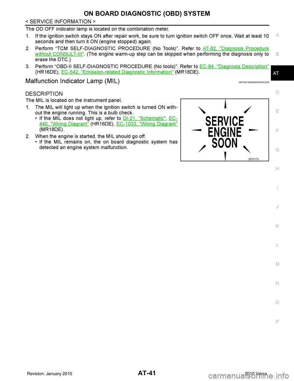
1. The MIL will light up when the ignition switch is turned ON with-
out the engine running. This is a bulb check.
• If the MIL does not light up, refer to DI-21, "
Schematic", EC-
440, "Wiring Diagram" (HR16DE), EC-1033, "Wiring Diagram"
(MR18DE).
2. When the engine is start ed, the MIL should go off.
• If the MIL remains on, the on board diagnostic system has detected an engine system malfunction.
SEF217U
Revision: January 20102010 Versa
Page 59 of 3745

AT-42
< SERVICE INFORMATION >
TROUBLE DIAGNOSIS
TROUBLE DIAGNOSIS
DTC Inspection Priority ChartINFOID:0000000005397235
If some DTCs are displayed at the same time, perform inspections one by one based on the following priority
chart.
NOTE:
If DTC “CAN COMM CIRCUIT” is displayed with other DTCs, first perform the trouble diagnosis for
DTC “CAN COMM CIRCUIT”. Refer to AT- 8 7
.
Fail-SafeINFOID:0000000005397236
The TCM has an electronic Fail-safe mode. This allows t he vehicle to be driven even if a major electrical input/
output device circuit is damaged.
Under Fail-Safe, the vehicle always runs in 3GR, even wit h a shift lever position of “1”, “2” or “D”. The cus-
tomer may complain of sluggish or poor acceleration.
Always follow the “ AT-43, "
How to Perform Trouble Diagnosis for Quick and Accurate Repair" ”.
The SELF-DIAGNOSIS results will be as follows:
• The first SELF-DIAGNOSIS will indicate damage to the vehicle speed signal or the output speed sensor.
• During the next SELF-DIAGNOSIS, performed after checking the sensor, no damages will be indicated.
FAIL-SAFE FUNCTION
The following fail-safe functions allow vehicles to be driven even when sensor, switch or solenoid malfunction
occurs.
Output Speed Sensor
Vehicle speed signal is input from combination meter.
Accelerator Pedal Position Signal and Throttle Position Signal
TCM controls the throttle opening angle to a predetermined fixed position to enable driving if a malfunctioning
signal is input to TCM.
Transmission Range Switch
When the multiple transmission range switch signals are input to TCM, the priority of selector lever position
becomes “D”, “N”, “R”, “2” and “1” in order by internal TCM determination.
The use of 4GR is inhibited until normal operation resumes. Because the hydraulic circuit of the control valve
is switched by manual valve according to the selector lever position, however, actual operating condition of
vehicle becomes as follows.
Shift Solenoid Valve A and B
If non-standard solenoid signal is sent to TCM, use of certain gears is limited. Refer to chart shown below.
Priority Detected items
1 CAN communication line
2 Except above
Actual lever positionTransmission range switch input signal Running status
“P” “P” position and other position signals P
“R” “R” position and other position signals R
“N” “N” position and other position signals N
“D” “D” position and other position signals D
1 ⇔ D2 ⇔ D3 ⇔ D4
“2” “2” position and other position signals (Except “1” position)
21 ⇔ 22 ⇔ 23
“2” position and “1” position signals 21 ⇔ 22
“1” “1” position and other position signals (Except “2” position)
11 ⇔ 12 ⇔ 13
“1” position and “2” position signals 11 ⇔ 12
Revision: January 20102010 Versa
Page 110 of 3745
P0705 TRANSMISSION RANGE SWITCH A
AT-93
< SERVICE INFORMATION >
D E
F
G H
I
J
K L
M A
B
AT
N
O P
NG >> GO TO 3.
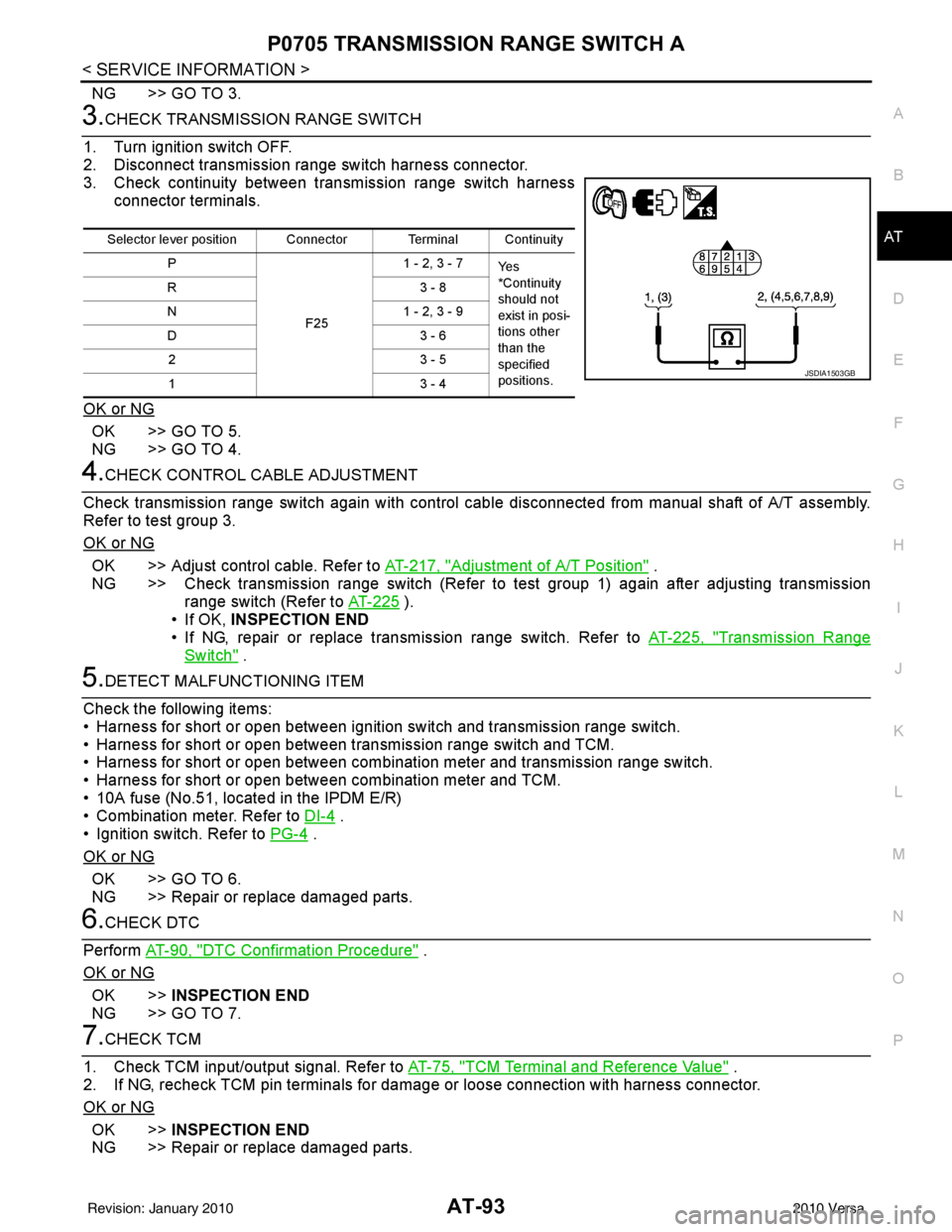
3.CHECK TRANSMISSION RANGE SWITCH
1. Turn ignition switch OFF.
2. Disconnect transmission range switch harness connector.
3. Check continuity between transmission range switch harness connector terminals.
OK or NG
OK >> GO TO 5.
NG >> GO TO 4.
4.CHECK CONTROL CABLE ADJUSTMENT
Check transmission range switch again with control cabl e disconnected from manual shaft of A/T assembly.
Refer to test group 3.
OK or NG
OK >> Adjust control cable. Refer to AT-217, "Adjustment of A/T Position" .
NG >> Check transmission range switch (Refer to test group 1) again after adjusting transmission range switch (Refer to AT-225
).
• If OK, INSPECTION END
• If NG, repair or replace transmission range switch. Refer to AT-225, "
Transmission Range
Switch" .
5.DETECT MALFUNCTIONING ITEM
Check the following items:
• Harness for short or open between ignition switch and transmission range switch.
• Harness for short or open between transmission range switch and TCM.
• Harness for short or open between combination meter and transmission range switch.
• Harness for short or open between combination meter and TCM.
• 10A fuse (No.51, located in the IPDM E/R)
• Combination meter. Refer to DI-4
.
• Ignition switch. Refer to PG-4
.
OK or NG
OK >> GO TO 6.
NG >> Repair or replace damaged parts.
6.CHECK DTC
Perform AT-90, "
DTC Confirmation Procedure" .
OK or NG
OK >> INSPECTION END
NG >> GO TO 7.
7.CHECK TCM
1. Check TCM input/output signal. Refer to AT-75, "
TCM Terminal and Reference Value" .
2. If NG, recheck TCM pin terminals for dam age or loose connection with harness connector.
OK or NG
OK >> INSPECTION END
NG >> Repair or replace damaged parts.
Selector lever position Connector Terminal Continuity
P
F251 - 2, 3 - 7
Ye s
*Continuity
should not
exist in posi-
tions other
than the
specified
positions.
R3
- 8
N 1 - 2, 3 - 9
D3 - 6
23 - 5
13 - 4
JSDIA1503GB
Revision: January 20102010 Versa
Page 190 of 3745
TR SW, OD SW AND CLOSED THROTTLE, WIDE OPEN THROTTLE POSITION
SIGNAL CIRCUIT
AT-173
< SERVICE INFORMATION >
DE
F
G H
I
J
K L
M A
B
AT
N
O P
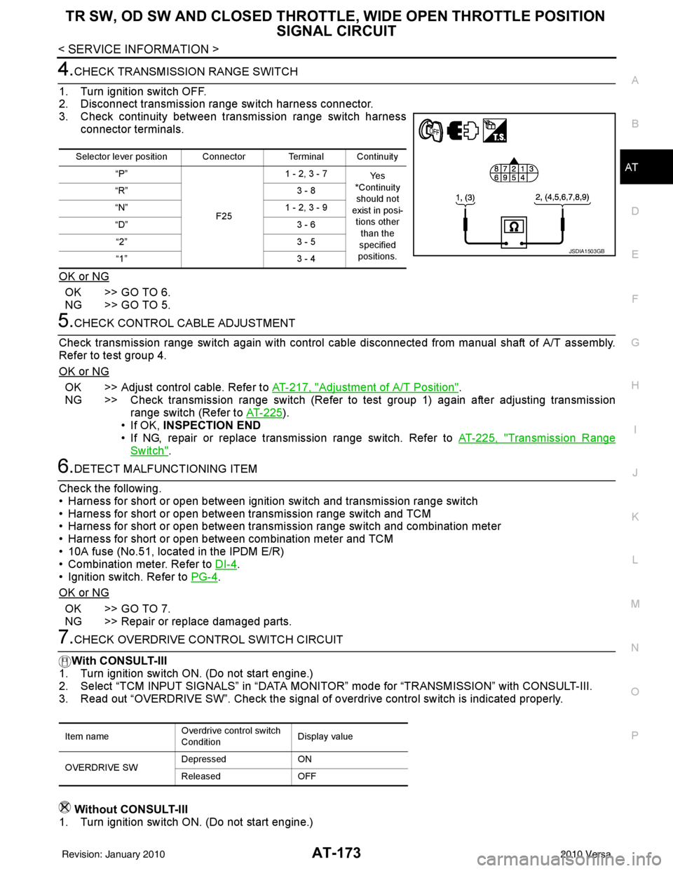
4.CHECK TRANSMISSION RANGE SWITCH
1. Turn ignition switch OFF.
2. Disconnect transmission range switch harness connector.
3. Check continuity between transmission range switch harness connector terminals.
OK or NG
OK >> GO TO 6.
NG >> GO TO 5.
5.CHECK CONTROL CABLE ADJUSTMENT
Check transmission range switch again with control cabl e disconnected from manual shaft of A/T assembly.
Refer to test group 4.
OK or NG
OK >> Adjust control cable. Refer to AT-217, "Adjustment of A/T Position".
NG >> Check transmission range switch (Refer to test group 1) again after adjusting transmission range switch (Refer to AT-225
).
• If OK, INSPECTION END
• If NG, repair or replace transmission range switch. Refer to AT-225, "
Transmission Range
Switch".
6.DETECT MALFUNCTIONING ITEM
Check the following.
• Harness for short or open between ignition switch and transmission range switch
• Harness for short or open between transmission range switch and TCM
• Harness for short or open between transmission range switch and combination meter
• Harness for short or open between combination meter and TCM
• 10A fuse (No.51, located in the IPDM E/R)
• Combination meter. Refer to DI-4
.
• Ignition switch. Refer to PG-4
.
OK or NG
OK >> GO TO 7.
NG >> Repair or replace damaged parts.
7.CHECK OVERDRIVE CO NTROL SWITCH CIRCUIT
With CONSULT-III
1. Turn ignition switch ON. (Do not start engine.)
2. Select “TCM INPUT SIGNALS” in “DATA MONI TOR” mode for “TRANSMISSION” with CONSULT-III.
3. Read out “OVERDRIVE SW”. Check the signal of ov erdrive control switch is indicated properly.
Without CONSULT-III
1. Turn ignition switch ON. (Do not start engine.)
Selector lever position Connector Terminal Continuity
“P”
F251 - 2, 3 - 7
Ye s
*Continuity should not
exist in posi-
tions other than the
specified
positions.
“R”
3 - 8
“N” 1 - 2, 3 - 9
“D” 3 - 6
“2” 3 - 5
“1” 3 - 4
JSDIA1503GB
Item nameOverdrive control switch
ConditionDisplay value
OVERDRIVE SW Depressed
ON
Released OFF
Revision: January 20102010 Versa
Page 191 of 3745
AT-174
< SERVICE INFORMATION >
TR SW, OD SW AND CLOSED THROTTLE, WIDE OPEN THROTTLE POSITION
SIGNAL CIRCUIT
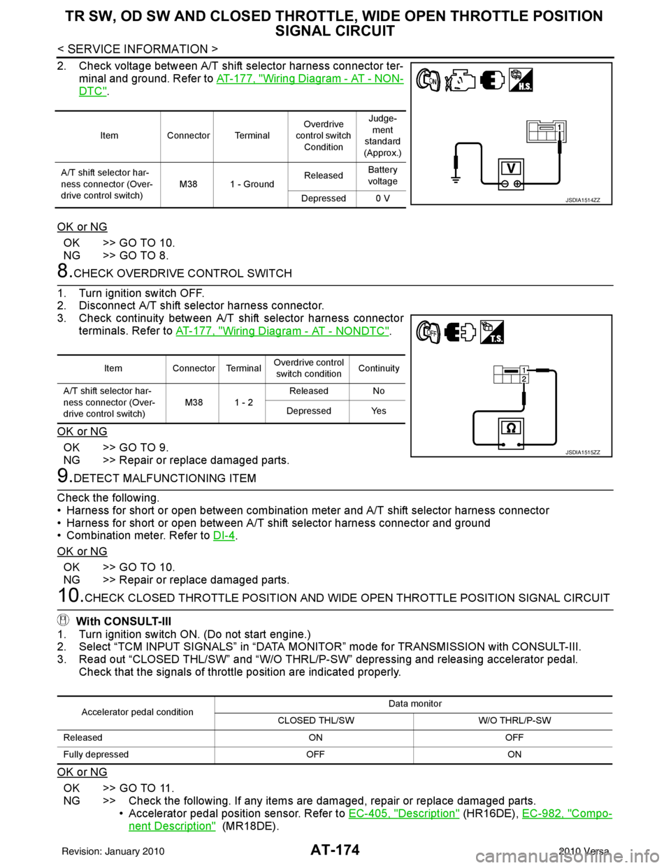
2. Check voltage between A/T shift selector harness connector ter-
minal and ground. Refer to AT-177, "
Wiring Diagram - AT - NON-
DTC".
OK or NG
OK >> GO TO 10.
NG >> GO TO 8.
8.CHECK OVERDRIVE CONTROL SWITCH
1. Turn ignition switch OFF.
2. Disconnect A/T shift selector harness connector.
3. Check continuity between A/T shift selector harness connector terminals. Refer to AT-177, "
Wiring Diagram - AT - NONDTC".
OK or NG
OK >> GO TO 9.
NG >> Repair or replace damaged parts.
9.DETECT MALFUNCTIONING ITEM
Check the following.
• Harness for short or open between combination meter and A/T shift selector harness connector
• Harness for short or open between A/T shift selector harness connector and ground
• Combination meter. Refer to DI-4
.
OK or NG
OK >> GO TO 10.
NG >> Repair or replace damaged parts.
10.CHECK CLOSED THROTTLE POSI TION AND WIDE OPEN THROTTLE POSITION SIGNAL CIRCUIT
With CONSULT-III
1. Turn ignition switch ON. (Do not start engine.)
2. Select “TCM INPUT SIGNALS” in “DATA MONITOR” mode for TRANSMISSION with CONSULT-III.
3. Read out “CLOSED THL/SW” and “W/O THRL/P-S W” depressing and releasing accelerator pedal.
Check that the signals of throttle position are indicated properly.
OK or NG
OK >> GO TO 11.
NG >> Check the following. If any items are damaged, repair or replace damaged parts. • Accelerator pedal position sensor. Refer to EC-405, "
Description" (HR16DE), EC-982, "Compo-
nent Description" (MR18DE).
Item Connector Terminal Overdrive
control switch
Condition Judge-
ment
standard
(Approx.)
A/T shift selector har-
ness connector (Over-
drive control switch) M38 1 - Ground
Released
Battery
voltage
Depressed 0 V
JSDIA1514ZZ
Item Connector Terminal Overdrive control
switch condition Continuity
A/T shift selector har-
ness connector (Over-
drive control switch) M38 1 - 2
Released No
Depressed Yes
JSDIA1515ZZ
Accelerator pedal condition Data monitor
CLOSED THL/SW W/O THRL/P-SW
Released ONOFF
Fully depressed OFFON
Revision: January 20102010 Versa