2010 NISSAN TIIDA battery replacement
[x] Cancel search: battery replacementPage 239 of 3745
AT-222
< SERVICE INFORMATION >
ON-VEHICLE SERVICE
ON-VEHICLE SERVICE
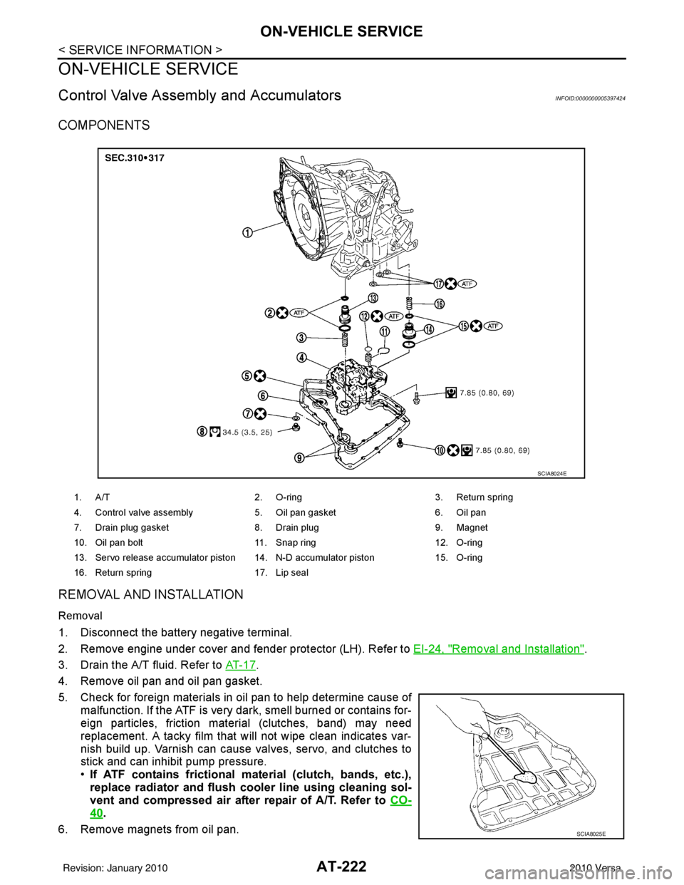
Control Valve Assembly and AccumulatorsINFOID:0000000005397424
COMPONENTS
REMOVAL AND INSTALLATION
Removal
1. Disconnect the battery negative terminal.
2. Remove engine under cover and fender protector (LH). Refer to EI-24, "
Removal and Installation".
3. Drain the A/T fluid. Refer to AT- 1 7
.
4. Remove oil pan and oil pan gasket.
5. Check for foreign materials in oil pan to help determine cause of malfunction. If the ATF is very dark, smell burned or contains for-
eign particles, friction material (clutches, band) may need
replacement. A tacky film that will not wipe clean indicates var-
nish build up. Varnish can cause valves, servo, and clutches to
stick and can inhibit pump pressure.
•If ATF contains frictional ma terial (clutch, bands, etc.),
replace radiator and flush cool er line using cleaning sol-
vent and compressed air after repair of A/T. Refer to CO-
40.
6. Remove magnets from oil pan.
1. A/T 2. O-ring 3. Return spring
4. Control valve assembly 5. Oil pan gasket6. Oil pan
7. Drain plug gasket 8. Drain plug9. Magnet
10. Oil pan bolt 11. Snap ring 12. O-ring
13. Servo release accumulator piston 14. N-D accumulator piston 15. O-ring
16. Return spring 17. Lip seal
SCIA8024E
SCIA8025E
Revision: January 20102010 Versa
Page 511 of 3745

BL-2
Keyfob Function (Unlock) Check ............................82
ID Code Entry Procedure .................................... ...82
Keyfob Battery Replacement ............................... ...85
Removal and Installation of Remote Keyless Entry
Receiver .............................................................. ...
85
INTELLIGENT KEY SYSTEM ............................86
Component Parts and Harness Connector Loca-
tion ....................................................................... ...
86
System Description .................................................88
CAN Communication System Description ..............95
Schematic ............................................................ ...96
Wiring Diagram - I/KEY - ..................................... ...98
Intelligent Key Unit Har ness Connector Terminal
Layout .................................................................. ..
108
Terminal and Reference Value for Intelligent Key
Unit ........................................................................
108
Steering Lock Solenoid Harness Connector Ter-
minal Layout ..........................................................
110
Terminal and Reference Value for Steering Lock
Solenoid .................................................................
110
Terminal and Reference Value for BCM ................111
Trouble Diagnosis Procedure ................................115
CONSULT-III Functions (INTELLIGENT KEY) ......117
CONSULT-III Application Item ............................. ..117
Trouble Diagnosis Symptom Chart ........................119
CAN Communication System Inspection ...............126
Power Supply and Ground Circuit Inspection ........126
Key Switch (Intelligent Key Unit Input) Check .......127
Key Switch (BCM Input) Check .............................128
Ignition Knob Switch Check ................................. ..129
Door Switch Check (Hatchback) ............................131
Door Switch Check (Sedan) ..................................133
Door Request Switch Check ..................................135
Back Door Request Switch Check (Hatchback) ....137
Trunk Opener Request Switch Check (Sedan) ... ..138
Unlock Sensor Check ............................................140
Intelligent Key Warning Buzzer(s) Check ..............142
Outside Key Antenna (Dri ver Side and Passenger
Side) Check ......................................................... ..
143
Outside Key Antenna (Rear Bumper) Check .........144
Inside Key Antenna Check ....................................146
Steering Lock Solenoid Check ............................ ..147
Key Interlock Solenoid (With M/T) Check ..............149
Ignition Switch Position Check ............................ ..150
Stop Lamp Switch Check (With CVT or A/T) ....... ..150
Stop Lamp Switch Check (With M/T) .....................152
CVT or A/T Shift Selector (Park Position Switch)
Check .................................................................. ..
153
"P-SHIFT" Warning Lamp (With CVT or A/T)
Check ....................................................................
154
"LOCK" Warning Lamp (With M/T) Check .............155
"KEY" Warning Lamp (RED) Check ......................155
"KEY" Warning Lamp (G REEN) Check .................155
Check Warning Chime in Combination Meter ........156
Hazard Function Check .........................................156
Horn Function Check .... .........................................157
Headlamp Function Chec k ....................................157
Intelligent Key Battery Replacement ................... ..158
Remote Keyless Entry Function ............................158
Removal and Installation of Intelligent Key Unit ... .158
DOOR ...............................................................160
Fitting Adjustment ................................................ .160
Removal and Installation .......................................163
FRONT DOOR LOCK ..................................... ..166
Component Parts Location .................................. .166
Removal and Installation .......................................166
REAR DOOR LOCK ....................................... ..169
Component Parts Location .................................. .169
Removal and Installation .......................................169
BACK DOOR LOCK ....................................... ..172
Component Parts and Harness Connector Loca-
tion ....................................................................... .
172
System Description ...............................................172
Wiring Diagram - B/DOOR - ..................................173
Terminal and Reference Value for BCM ...............175
Terminal and Reference Value for Intelligent Key
Unit ....................................................................... .
179
CONSULT-III Function (BCM) ..............................181
Work Flow .............................................................182
Trouble Diagnosis Chart by Symptom ..................182
BCM Power Supply and Ground Circuit Inspection
.
182
Check Back Door Opener Switch Circuit (Without
Intelligent Key or Power Windows) ...................... .
183
Check Back Door Opener Switch Circuit (Without
Intelligent Key, with Power Windows) .................. .
186
Check Back Door Opener Switch Circuit (With In-
telligent Key) ........................................................ .
188
Check Back Door Lock Assembly (Actuator) Cir-
cuit ........................................................................
190
Removal and Installation .......................................192
TRUNK LID ..................................................... ..193
Fitting Adjustment ................................................ .193
Trunk Lid Assembly ..............................................193
Trunk Lid Lock ......................................................194
Trunk Lid Striker ....................................................194
Trunk Lid Stay Disposal ........................................195
TRUNK LID OPENER .......................................196
Component Parts and Harness Connector Loca-
tion ....................................................................... .
196
System Description ...............................................196
Wiring Diagram - TLID - ........................................197
Terminal and Reference Value for BCM ...............199
Terminal and Reference Value for Intelligent Key
Unit ....................................................................... .
203
CONSULT-III Function (BCM) ..............................205
Work Flow .............................................................206
Trouble Diagnosis Chart by Symptom ..................206
BCM Power Supply and Ground Circuit Inspection
.
206
Check Trunk Lid Opener Switch Circuit (Without
Intelligent Key or Power Windows) ...................... .
207
Revision: January 20102010 Versa
Page 594 of 3745
REMOTE KEYLESS ENTRY SYSTEMBL-85
< SERVICE INFORMATION >
C
DE
F
G H
J
K L
M A
B
BL
N
O P
• When registering an additional keyfob, the existing ID codes in memory may or may not be erased. If five ID
codes are stored in memory, when an additional code is registered, only the oldest code is erased. If less
than five ID codes are stored in memory, when an additional ID code is registered, the new ID code is added
and no ID codes are erased.
• If you need to activate more than two additional new keyfobs, repeat the procedure “Additional ID code
entry” for each new keyfob.
• Entry of maximum five ID codes is allowed. When mo re than five ID codes are entered, the oldest ID code
will be erased.
• Even if same ID code that is already in the memory is input, the same ID code can be entered. The code is
counted as an additional code.
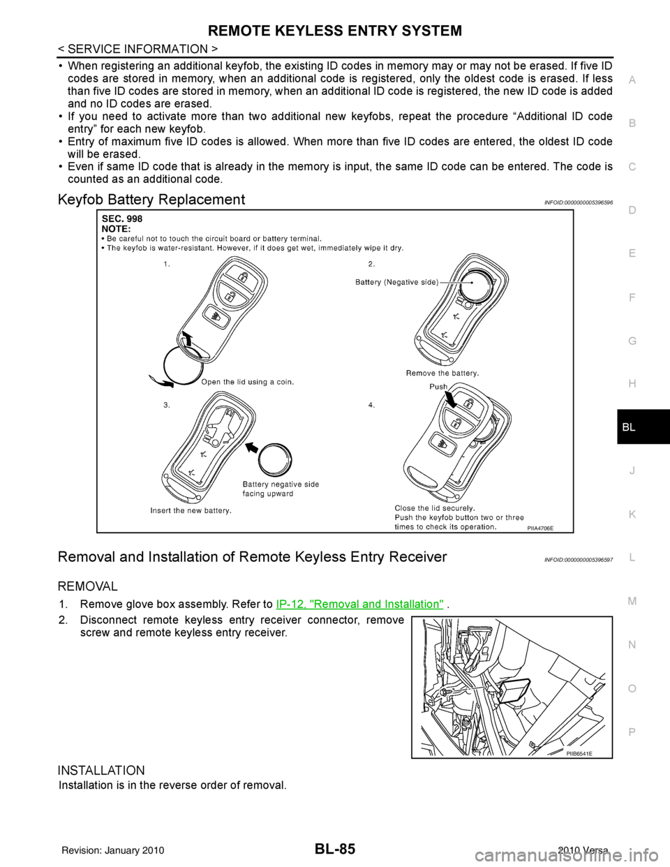
Keyfob Battery ReplacementINFOID:0000000005396596
Removal and Installation of Re mote Keyless Entry ReceiverINFOID:0000000005396597
REMOVAL
1. Remove glove box assembly. Refer to IP-12, "Removal and Installation" .
2. Disconnect remote keyless entry receiver connector, remove screw and remote keyless entry receiver.
INSTALLATION
Installation is in the reverse order of removal.
PIIA4706E
PIIB6541E
Revision: January 20102010 Versa
Page 624 of 3745
INTELLIGENT KEY SYSTEMBL-115
< SERVICE INFORMATION >
C
DE
F
G H
J
K L
M A
B
BL
N
O P
1: With Intelligent Key
2: Without Intelligent Key
3: Hatchback without Intelligent Key
4: Sedan without Intelligent Key
5: Hatchback
6: Sedan
7: With power door locks
8: With power windows
Trouble Diagnosis ProcedureINFOID:0000000005396608
PRELIMINARY CHECK
1.GET SYMPTOMS
Listen to customer c oncerns. (Get symptoms)
NOTE:
If customer reports a “No start” condition, request all Intelligent Keys to be brought to the dealer in case of
Intelligent Key system malfunction.
Intelligent Key or mechanical key service request>>For further information, refer to CONSULT-III operation
manual.
Malfunctions>>GO TO 2
2.CHECK BCM CONFIGURATION
Confirm BCM configuration for "I- KEY" is set to "WITH". Refer to BCS-19, "
Configuration".
OK or NG
OK >> GO TO 3
NG >> Change BCM configuration for "I-KEY" to "WITH". Refer to BCS-19, "
Configuration".
3.START ENGINE WITH INTELLIGENT KEY
Check if the engine could be started by all registered Intelligent Keys.
The engine cannot be started by some Intelligent Keys>>Int elligent Key is low battery or malfunction. Refer
to BL-158, "
Intelligent Key Battery Replacement".
The engine cannot be started by all Intelligent Keys >> GO TO 4
657SB All door lock actuators
(lock) Output OFFOFF (neutral)
0V
ON (lock) Battery voltage
66
7G Front door lock actua-
tor RH, rear door lock
actuators LH/RH (un-
lock) Output OFFOFF (neutral)
0V
ON (unlock) Battery voltage
67 B Ground Input ON—0V
68
8L Power window power
supply (RAP)
Output —Ignition switch ON
Battery voltage
Within 45 seconds after igni-
tion switch OFF Battery voltage
More than 45 seconds after ig-
nition switch OFF 0V
When front door LH or RH is
open or power window timer
operates 0V
69
8P Battery power supply OutputOFF
— Battery voltage
70 Y Battery power supply Input OFF —Battery voltage
Te r m i n a l
Wire
color Signal name Signal
input/
output Measuring condition
Reference value or waveform
(Approx.)
Ignition
switch Operation or condition
Revision: January 20102010 Versa
Page 667 of 3745
BL-158
< SERVICE INFORMATION >
INTELLIGENT KEY SYSTEM
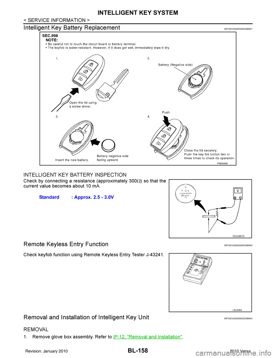
Intelligent Key Battery Replacement
INFOID:0000000005396641
INTELLIGENT KEY BATTERY INSPECTION
Check by connecting a resistance (approximately 300 Ω) so that the
current value becomes about 10 mA.
Remote Keyless Entry FunctionINFOID:0000000005396642
Check keyfob function using Remote Keyless Entry Tester J-43241.
Removal and Installation of Intelligent Key UnitINFOID:0000000005396643
REMOVAL
1. Remove glove box assembly. Refer to IP-12, "Removal and Installation".
PIIB5065E
Standard : Approx. 2.5 - 3.0V
OCC0607D
LEL946A
Revision: January 20102010 Versa
Page 766 of 3745
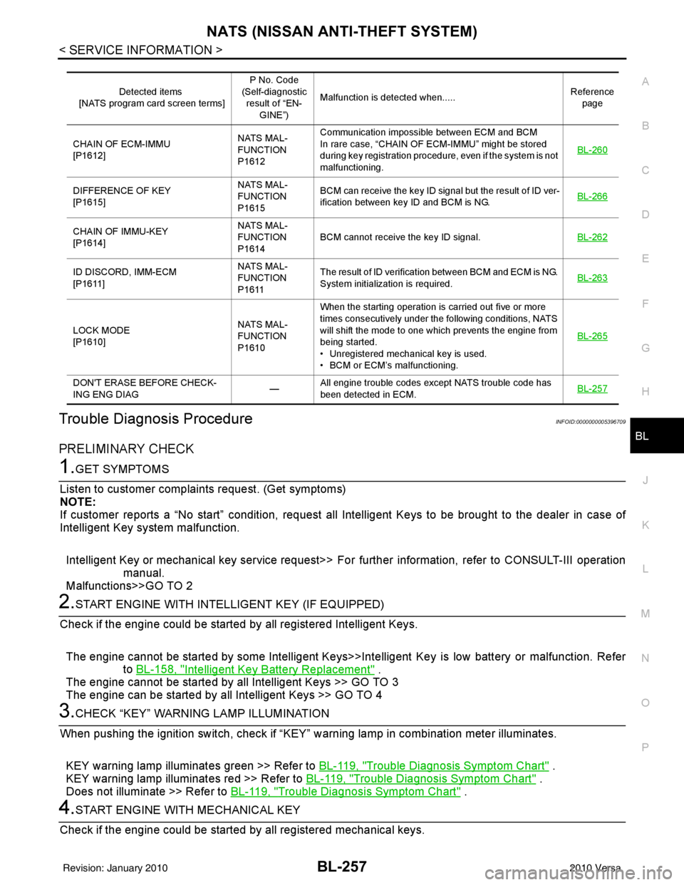
NATS (NISSAN ANTI-THEFT SYSTEM)BL-257
< SERVICE INFORMATION >
C
DE
F
G H
J
K L
M A
B
BL
N
O P
Trouble Diagnosis ProcedureINFOID:0000000005396709
PRELIMINARY CHECK
1.GET SYMPTOMS
Listen to customer complain ts request. (Get symptoms)
NOTE:
If customer reports a “No start” condition, request all Intelligent Keys to be brought to the dealer in case of
Intelligent Key system malfunction.
Intelligent Key or mechanical key service request>> Fo r further information, refer to CONSULT-III operation
manual.
Malfunctions>>GO TO 2
2.START ENGINE WITH INTELLIGENT KEY (IF EQUIPPED)
Check if the engine could be started by all registered Intelligent Keys.
The engine cannot be started by some Intelligent Keys>>Int elligent Key is low battery or malfunction. Refer
to BL-158, "
Intelligent Key Battery Replacement" .
The engine cannot be started by all Intelligent Keys >> GO TO 3
The engine can be started by all Intelligent Keys >> GO TO 4
3.CHECK “KEY” WARNING LAMP ILLUMINATION
When pushing the ignition switch, check if “KEY” warning lamp in combination meter illuminates.
KEY warning lamp illuminates green >> Refer to BL-119, "
Trouble Diagnosis Symptom Chart" .
KEY warning lamp illuminates red >> Refer to BL-119, "
Trouble Diagnosis Symptom Chart" .
Does not illuminate >> Refer to BL-119, "
Trouble Diagnosis Symptom Chart" .
4.START ENGINE WITH MECHANICAL KEY
Check if the engine could be started by all registered mechanical keys.
Detected items
[NATS program card screen terms] P No. Code
(Self-diagnostic result of “EN-
GINE”) Malfunction is detected when.....
Reference
page
CHAIN OF ECM-IMMU
[P1612] NATS MAL-
FUNCTION
P1612Communication impossible between ECM and BCM
In rare case, “CHAIN OF ECM-IMMU” might be stored
during key registration procedure, even if the system is not
malfunctioning.
BL-260
DIFFERENCE OF KEY
[P1615]NATS MAL-
FUNCTION
P1615BCM can receive the key ID signal but the result of ID ver-
ification between key ID and BCM is NG.
BL-266
CHAIN OF IMMU-KEY
[P1614]NATS MAL-
FUNCTION
P1614
BCM cannot receive the key ID signal.
BL-262
ID DISCORD, IMM-ECM
[P1611]NATS MAL-
FUNCTION
P1611The result of ID verification between BCM and ECM is NG.
System initialization is required.
BL-263
LOCK MODE
[P1610]NATS MAL-
FUNCTION
P1610When the starting operation is carried out five or more
times consecutively under the following conditions, NATS
will shift the mode to one which prevents the engine from
being started.
• Unregistered mechanical key is used.
• BCM or ECM’s malfunctioning.
BL-265
DON'T ERASE BEFORE CHECK-
ING ENG DIAG
—All engine trouble codes except NATS trouble code has
been detected in ECM.
BL-257
Revision: January 20102010 Versa
Page 1064 of 3745
![NISSAN TIIDA 2010 Service Repair Manual TROUBLE DIAGNOSISCVT-31
< SERVICE INFORMATION > [RE0F08B]
D
E
F
G H
I
J
K L
M A
B
CVT
N
O P
TCM Power Supply (Memory Back-up)
Transaxle assembly is protected by limiting the engine torque when the mem NISSAN TIIDA 2010 Service Repair Manual TROUBLE DIAGNOSISCVT-31
< SERVICE INFORMATION > [RE0F08B]
D
E
F
G H
I
J
K L
M A
B
CVT
N
O P
TCM Power Supply (Memory Back-up)
Transaxle assembly is protected by limiting the engine torque when the mem](/manual-img/5/57397/w960_57397-1063.png)
TROUBLE DIAGNOSISCVT-31
< SERVICE INFORMATION > [RE0F08B]
D
E
F
G H
I
J
K L
M A
B
CVT
N
O P
TCM Power Supply (Memory Back-up)
Transaxle assembly is protected by limiting the engine torque when the memory back-up power supply (for
controlling) from the battery is not supplied to TCM.
Normal statues is restored when turning the ignition switch
OFF to ON after the normal power supply.
How to Perform Trouble Diagnosis for Quick and Accurate RepairINFOID:0000000005397787
INTRODUCTION
The TCM receives a signal from the vehicle speed sensor, transmission range switch and provides shift con-
trol or lock-up control via CVT solenoid valves.
The TCM also communicates with the ECM by means of a signal
sent from sensing elements used wit h the OBD-related parts of the
CVT system for malfunction-diagnos tic purposes. The TCM is capa-
ble of diagnosing malfunctioning parts while the ECM can store mal-
functions in its memory.
Input and output signals must always be correct and stable in the
operation of the CVT system. The CVT system must be in good
operating condition and be free of valve seizure, solenoid valve mal-
function, etc.
It is much more difficult to diagnose an error that occurs intermit-
tently rather than continuously. Most intermittent errors are caused
by poor electric connections or impr oper wiring. In this case, careful
checking of suspected circuits may help prevent the replacement of
good parts.
A visual check only may not find t he cause of the errors. A road test
with CONSULT-III (or GST) or a circuit tester connected should be
performed. Follow the "WORK FLOW" .
Before undertaking actual checks, take a few minutes to talk with a
customer who approaches with a driveability complaint. The cus-
tomer can supply good information about such errors, especially
intermittent ones. Find out what symptoms are present and under
what conditions they occur. A “DIAGNOSTIC WORKSHEET” as
shown on the example (Refer to "Diagnostic Worksheet Chart" )
should be used.
Start your diagnosis by looking for “conventional” errors first. This will
help troubleshoot driveability errors on an electronically controlled
engine vehicle.
Also check related Service bulletins.
WORK FLOW
A good understanding of the malfunction conditions can make troubleshooting faster and more accurate.
In general, each customer feels differently about a malf unction. It is important to fully understand the symp-
toms or conditions for a customer complaint.
Make good use of the two sheets provided, "Information From Customer" and "Diagnostic Worksheet Chart" ,
to perform the best troubleshooting possible.
Work Flow Chart
SAT631IB
SAT632I
SEF234G
Revision: January 20102010 Versa
Page 1595 of 3745
![NISSAN TIIDA 2010 Service Repair Manual EC-330
< COMPONENT DIAGNOSIS >[HR16DE]
P0456 EVAP CONTROL SYSTEM
• Use only a genuine NISSAN rubber tube as a replacement.
DTC CONFIRMATION PROCEDURE
1.INSPECTION START
Do you have CONSULT-III?
Do y NISSAN TIIDA 2010 Service Repair Manual EC-330
< COMPONENT DIAGNOSIS >[HR16DE]
P0456 EVAP CONTROL SYSTEM
• Use only a genuine NISSAN rubber tube as a replacement.
DTC CONFIRMATION PROCEDURE
1.INSPECTION START
Do you have CONSULT-III?
Do y](/manual-img/5/57397/w960_57397-1594.png)
EC-330
< COMPONENT DIAGNOSIS >[HR16DE]
P0456 EVAP CONTROL SYSTEM
• Use only a genuine NISSAN rubber tube as a replacement.
DTC CONFIRMATION PROCEDURE
1.INSPECTION START
Do you have CONSULT-III?
Do you have CONSULT-III?
YES >> GO TO 2.
NO >> GO TO 4.
2.PRECONDITIONING
If DTC Confirmation Procedure has been previously conducted, always turn ignition switch OFF and wait at
least 10 seconds before conducting the next test.
NOTE:
• If DTC P0456 is displayed with P0442, firs t perform trouble diagnosis for DTC P0456.
• After repair, make sure that the hoses and clips are installed properly.
• Make sure that EVAP hoses are connected to EVAP canister purge volume control solenoid valve
properly.
TESTING CONDITION:
• Open engine hood before conducting following procedure.
• If any of following conditions are met just be fore the DTC CONFIRMATION PROCEDURE, leave the
vehicle for more than 1 hour.
- Fuel filler cap is removed.
- Fuel is refilled or drained.
- EVAP component parts is/are removed.
• Before performing the following procedure, confirm th at battery voltage is more than 11 V at idle.
>> GO TO 3.
3.PERFORM DTC CONFIRMATION PROCEDURE
With CONSULT-III
1. Turn ignition switch ON and select “DATA MONITOR” mode with CONSULT-III.
2. Make sure the following conditions are met.
FUEL LEVEL SE: 0.25 - 1.4 V
COOLAN TEMP/S: 0 - 32 °C (32 - 90° F)
FUEL T/TMP SE: 0 - 35° C (32 - 95°F)
INT A/TEMP SE: More than 0° C (32°F)
If NG, turn ignition switch OFF and leave the vehicle in a cool place (soak the vehicle) or refilling/draining
fuel until the output voltage condition of the “FUEL LEVEL SE” meets within the range above and leave
the vehicle for more than 1 hour. Then start from step 1.
3. Turn ignition switch OFF and wait at least 10 seconds.
4. Turn ignition switch ON.
5. Select “EVAP V/S LEAK P0456/P1456” of “EVAPO RATIVE SYSTEM” in “DTC WORK SUPPORT” mode
with CONSULT-III.
Follow the instruction displayed.
NOTE:
If the engine speed canno t be maintained within the range displayed on CONSULT-III screen, go to
EC-20, "
BASIC INSPECTION : Special Repair Requirement".
Which is displayed on CONSULT-III?
OK >> INSPECTION END
NG >> Go to EC-331, "
Diagnosis Procedure".
4.PERFORM COMPONENT FUNCTION CHECK
Perform component function check. Refer to EC-331, "
Component Function Check".
NOTE:
Use component function check to check the overall function of the EVAP very small leak function. During this
check, a 1st trip DTC might not be confirmed.
Is the inspection result normal?
YES >> INSPECTION END
Revision: January 20102010 Versa