Page 383 of 3745
AT-366
< SERVICE INFORMATION >
ASSEMBLY
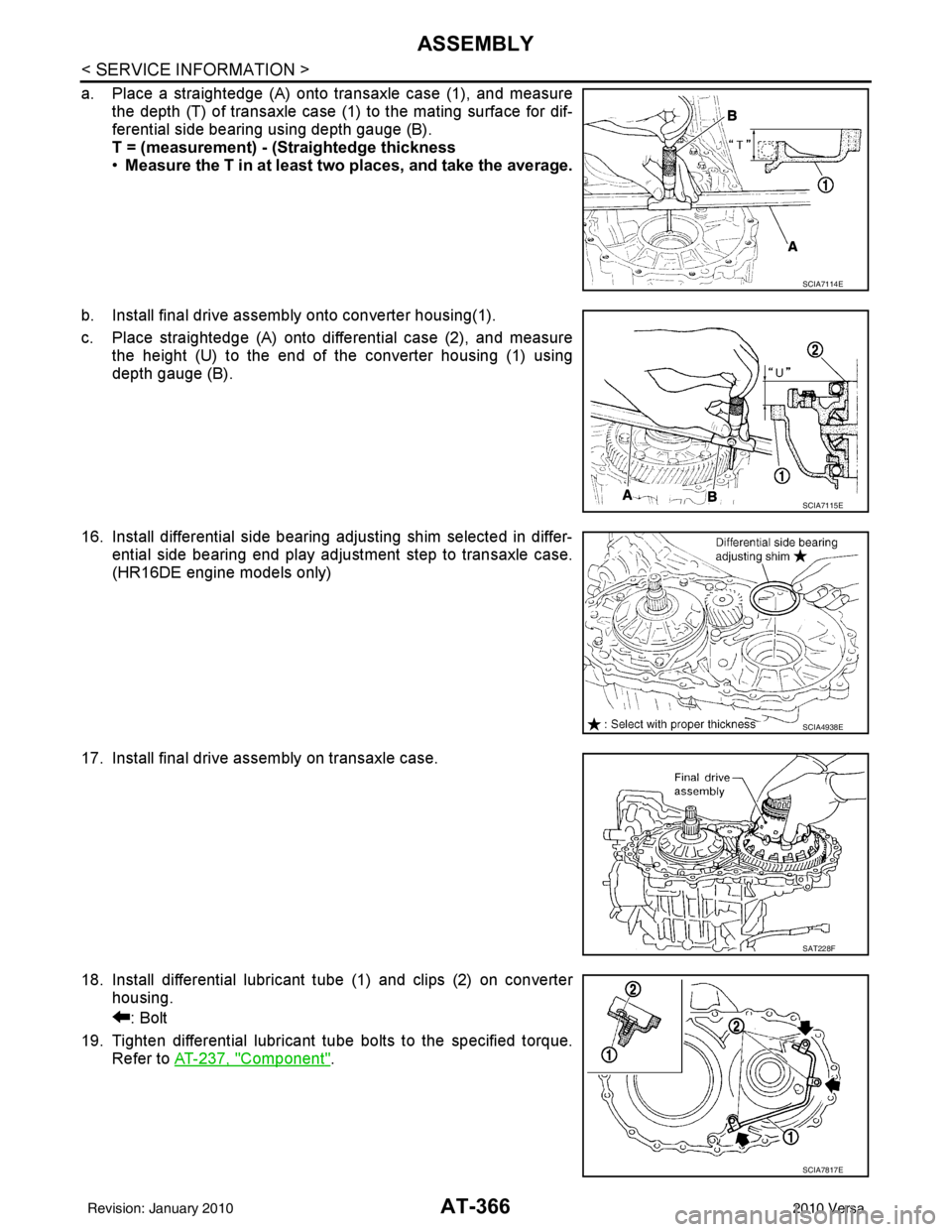
a. Place a straightedge (A) onto transaxle case (1), and measurethe depth (T) of transaxle case (1) to the mating surface for dif-
ferential side bearing using depth gauge (B).
T = (measurement) - (Straightedge thickness
•Measure the T in at least two places, and take the average.
b. Install final drive assembly onto converter housing(1).
c. Place straightedge (A) onto differential case (2), and measure the height (U) to the end of the converter housing (1) using
depth gauge (B).
16. Install differential side bearing adjusting shim selected in differ- ential side bearing end play adjustment step to transaxle case.
(HR16DE engine models only)
17. Install final drive assembly on transaxle case.
18. Install differential lubricant tube (1) and clips (2) on converter housing.
: Bolt
19. Tighten differential lubricant tube bolts to the specified torque. Refer to AT-237, "
Component".
SCIA7114E
SCIA7115E
SCIA4938E
SAT228F
SCIA7817E
Revision: January 20102010 Versa
Page 522 of 3745
HOODBL-13
< SERVICE INFORMATION >
C
DE
F
G H
J
K L
M A
B
BL
N
O P
HOOD
Fitting AdjustmentINFOID:0000000005396547
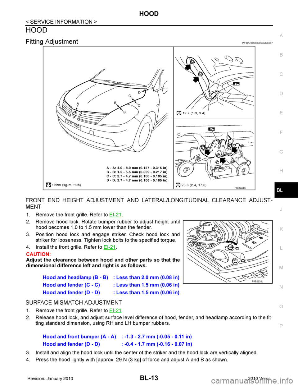
FRONT END HEIGHT ADJUSTMENT AND LA TERAL/LONGITUDINAL CLEARANCE ADJUST-
MENT
1. Remove the front grille. Refer to EI-21.
2. Remove hood lock. Rotate bumper rubber to adjust height until hood becomes 1.0 to 1.5 mm lower than the fender.
3. Position hood lock and engage striker. Check hood lock and striker for looseness. Tighten lock bolts to the specified torque.
4. Install the front grille. Refer to EI-21
.
CAUTION:
Adjust the clearance between hood and other parts so that the
dimensional difference left and right is as follows.
SURFACE MISMATCH ADJUSTMENT
1. Remove the front grille. Refer to EI-21.
2. Release hood lock, and adjust surface level difference of hood, fender, and headlamp according to the fit- ting standard dimension, using RH and LH bumper rubbers.
3. Install and align the hood lock until the center of the striker and the hood lock are vertically aligned.
4. Press the hood lightly with [approx. 29 N (3 kg] of force and adjust A and B as shown.
PIIB6508E
Hood and headlamp (B - B) : Less than 2.0 mm (0.08 in)
Hood and fender (C - C) : Less than 1.5 mm (0.06 in)
Hood and fender (D - D) : Less than 1.5 mm (0.06 in)PIIB2526J
Hood and front bumper (A - A) : -1.3 - 2.7 mm (-0.05 - 0.11 in)
Hood and fender (D - D) : -0.4 - 1.7 mm (-0.16 - 0.07 in)
Revision: January 20102010 Versa
Page 669 of 3745
BL-160
< SERVICE INFORMATION >
DOOR
DOOR
Fitting AdjustmentINFOID:0000000005396644
FRONT DOOR
Longitudinal Clearance at Front End
Access from inside the fender to loosen the hinge bolts. Raise the front door at rear end to adjust.
Surface Height Adjustment
Loosen the front door bolts, and adjust the surface height difference of fender and front door according to the
fitting standard dimension.
Striker Adjustment
1. Front fender2. Front door outer3. Rear door outer
4. Rear fender 5. Front door weatherstrip 6. Front door sash
7. Rear door weatherstrip 8. Rear door sash
PIIB6516E
Revision: January 20102010 Versa
Page 670 of 3745
DOOR
BL-161
< SERVICE INFORMATION >
C
D E
F
G H
J
K L
M A
B
BL
N
O P
REAR DOOR
Longitudinal Clearance and Surface Height Adjustment at Front End
1. Remove the center pillar upper and lower garnishes. Refer to EI-39.
2. Access from inside the vehicle to loosen the hinge nuts. Open the rear door, and raise the rear door at
rear end to adjust.
Surface Height Adjustment
Loosen the front door striker bolts and rear door hinge nu ts, and adjust the surface height difference of front
and rear doors according to the fitting standard dimension.
Striker Adjustment
BACK DOOR
Longitudinal Clearance and Surface Height Adjustment
16.7 N·m (1.7 kg-m, 12 ft-lb)
PIIB2804J
16.7 N·m (1.7 kg-m, 12 ft-lb)
PIIB2804J
Revision: January 20102010 Versa
Page 702 of 3745
TRUNK LIDBL-193
< SERVICE INFORMATION >
C
DE
F
G H
J
K L
M A
B
BL
N
O P
TRUNK LID
Fitting AdjustmentINFOID:0000000005396664
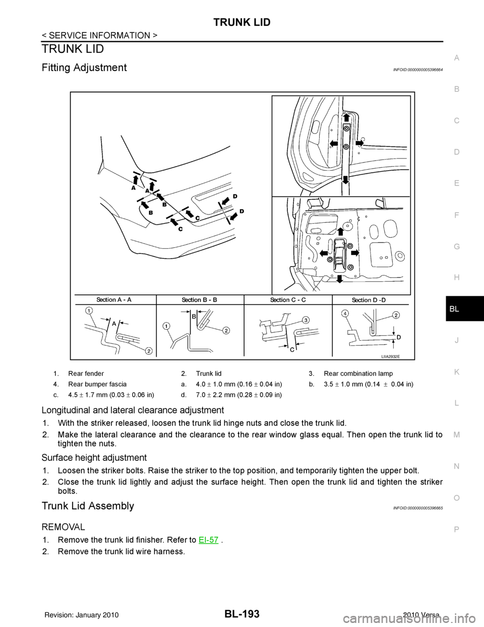
Longitudinal and latera l clearance adjustment
1. With the striker released, loosen the trunk lid hinge nuts and close the trunk lid.
2. Make the lateral clearance and the clearance to the rear window glass equal. Then open the trunk lid to
tighten the nuts.
Surface height adjustment
1. Loosen the striker bolts. Raise the striker to t he top position, and temporarily tighten the upper bolt.
2. Close the trunk lid lightly and adjust the surface height. Then open the trunk lid and tighten the striker bolts.
Trunk Lid AssemblyINFOID:0000000005396665
REMOVAL
1. Remove the trunk lid finisher. Refer to EI-57 .
2. Remove the trunk lid wire harness.
1. Rear fender 2. Trunk lid3. Rear combination lamp
4. Rear bumper fascia a. 4.0 ± 1.0 mm (0.16 ± 0.04 in) b. 3.5 ± 1.0 mm (0.14 ± 0.04 in)
c. 4.5 ± 1.7 mm (0.03 ± 0.06 in) d. 7.0 ± 2.2 mm (0.28 ± 0.09 in)
LIIA2932E
Revision: January 20102010 Versa
Page 854 of 3745
BR-6
< SERVICE INFORMATION >
BRAKE PEDAL
BRAKE PEDAL
Inspection and AdjustmentINFOID:0000000005396978
INSPECTION
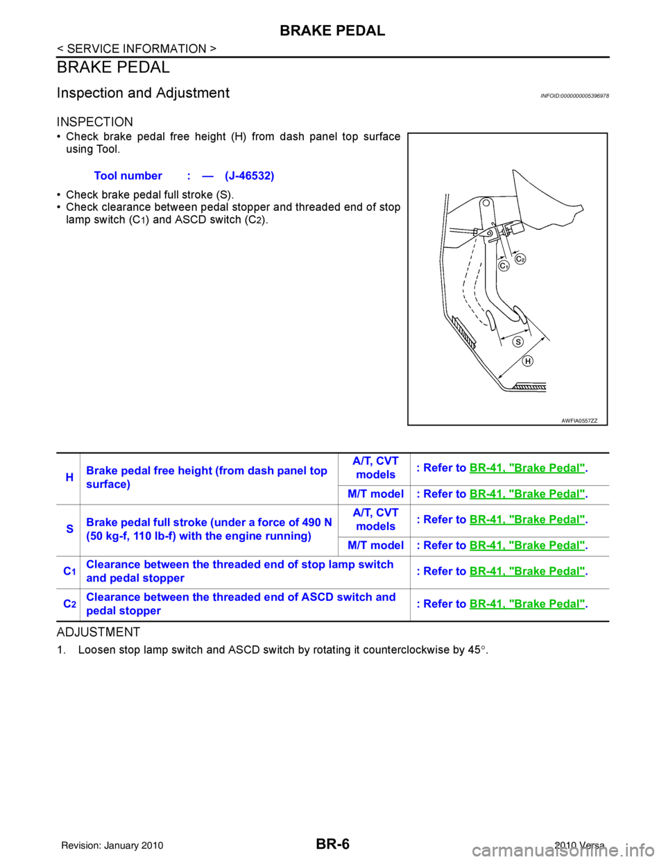
• Check brake pedal free height (H) from dash panel top surfaceusing Tool.
• Check brake pedal full stroke (S).
• Check clearance between pedal stopper and threaded end of stop lamp switch (C
1) and ASCD switch (C2).
ADJUSTMENT
1. Loosen stop lamp switch and ASCD switch by rotating it counterclockwise by 45 °.
Tool number : — (J-46532)
AWFIA0557ZZ
H
Brake pedal free height (from dash panel top
surface) A/T, CVT
models : Refer to
BR-41, "Brake Pedal".
M/T model : Refer to BR-41, "
Brake Pedal".
S Brake pedal full stroke (under a force of 490 N
(50 kg-f, 110 lb-f) with the engine running) A/T, CVT
models : Refer to
BR-41, "
Brake Pedal".
M/T model : Refer to BR-41, "
Brake Pedal".
C
1Clearance between the threaded end of stop lamp switch
and pedal stopper : Refer to
BR-41, "Brake Pedal".
C
2Clearance between the threaded end of ASCD switch and
pedal stopper : Refer to
BR-41, "Brake Pedal".
Revision: January 20102010 Versa
Page 870 of 3745
BR-22
< SERVICE INFORMATION >
BRAKE BOOSTER
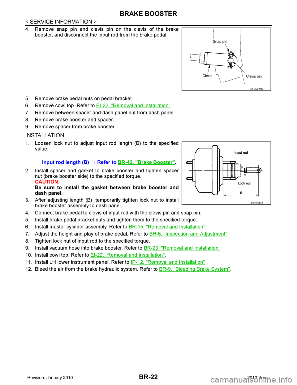
4. Remove snap pin and clevis pin on the clevis of the brakebooster, and disconnect the input rod from the brake pedal.
5. Remove brake pedal nuts on pedal bracket.
6. Remove cowl top. Refer to EI-22, "
Removal and Installation"
7. Remove between spacer and dash panel nut from dash panel.
8. Remove brake booster and spacer.
9. Remove spacer from brake booster.
INSTALLATION
1. Loosen lock nut to adjust input rod length (B) to the specified
value.
2. Install spacer and gasket to brake booster and tighten spacer nut (brake booster side) to the specified torque.
CAUTION:
Be sure to install the gasket between brake booster and
dash panel.
3. After adjusting length (B), temporarily tighten lock nut to install brake booster assembly to dash panel.
4. Connect brake pedal to clevis of input rod with the clevis pin and snap pin.
5. Install brake pedal bracket nuts and tighten them to the specified torque.
6. Install master cylinder assembly. Refer to BR-15, "
Removal and Installation".
7. Adjust the height and play of brake pedal. Refer to BR-6, "
Inspection and Adjustment".
8. Tighten lock nut of input rod to the specified torque.
9. Install vacuum hose into brake booster. Refer to BR-23, "
Removal and Installation".
10. Install cowl top. Refer to EI-22, "
Removal and Installation".
11. Install LH lower instrument panel. Refer to IP-12, "
Removal and Installation"
12. Bleed the air from the brake hydraulic system. Refer to BR-9, "Bleeding Brake System".
SFIA2044E
Input rod length (B) : Refer to BR-42, "Brake Booster".
SGIA0060E
Revision: January 20102010 Versa
Page 2259 of 3745
![NISSAN TIIDA 2010 Service Repair Manual EC-994
< SERVICE INFORMATION >[MR18DE]
DTC P2A00 A/F SENSOR 1
• Harness for open or short between A/F sensor 1 and fuse
>> Repair or replace harness or connectors.
8.CHECK A/F SENSOR 1 INPUT SIGN AL NISSAN TIIDA 2010 Service Repair Manual EC-994
< SERVICE INFORMATION >[MR18DE]
DTC P2A00 A/F SENSOR 1
• Harness for open or short between A/F sensor 1 and fuse
>> Repair or replace harness or connectors.
8.CHECK A/F SENSOR 1 INPUT SIGN AL](/manual-img/5/57397/w960_57397-2258.png)
EC-994
< SERVICE INFORMATION >[MR18DE]
DTC P2A00 A/F SENSOR 1
• Harness for open or short between A/F sensor 1 and fuse
>> Repair or replace harness or connectors.
8.CHECK A/F SENSOR 1 INPUT SIGN AL CIRCUIT FOR OPEN AND SHORT
1. Turn ignition switch OFF.
2. Disconnect ECM harness connector.
3. Check harness continuity between the following terminals. Refer to Wiring Diagram.
4. Check harness continuity between ECM terminals 49, 53 or A/F sensor 1 terminals 1, 2 and ground. Refer to Wiring Diagram.
5. Also check harness for short to power.
OK or NG
OK >> GO TO 9.
NG >> Repair open circuit or short to ground or short to power in harness or connectors.
9.CHECK A/F SENSOR 1 HEATER
Refer to EC-652, "
Component Inspection".
OK or NG
OK >> GO TO 10.
NG >> GO TO 11.
10.CHECK INTERMITTENT INCIDENT
Perform EC-632
.
OK or NG
OK >> GO TO 11.
NG >> Repair or replace.
11 .REPLACE AIR FUEL RATIO (A/F) SENSOR 1
Replace air fuel ratio (A/F) sensor 1.
CAUTION:
• Discard any air fuel ratio (A/F) sensor which has been dropped from a height of more than 0.5 m (19.7 in) onto a hard surface such as a concrete floor; use a new one.
• Before installing new air fuel ratio (A/F) sensor, clean exhaust system threads using Heated Oxygen
Sensor Thread Cleaner tool J-43897-18 or J-43897-12 and approved anti-seize lubricant.
>> GO TO 12.
12.CONFIRM A/F ADJUSTMENT DATA
1. Turn ignition switch ON.
2. Select “A/F ADJ-B1” in “DAT A MONITOR” mode with CONSULT-III.
3. Make sure that “0.000” is displayed on CONSULT-III screen.
OK or NG
OK >> INSPECTION END
NG >> GO TO 13.
13.CLEAR THE SELF-LEARNING DATA
With CONSULT-III
A/F sensor 1 terminal ECM terminal
14 9
25 3
Continuity should exist.
Continuity should not exist.
Revision: January 20102010 Versa