2010 JAGUAR XFR charging
[x] Cancel search: chargingPage 1326 of 3039
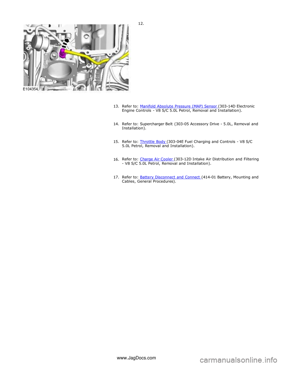
Engine Controls - V8 S/C 5.0L Petrol, Removal and Installation).
14. Refer to: Supercharger Belt (303-05 Accessory Drive - 5.0L, Removal and
Installation).
15. Refer to: Throttle Body (303-04E Fuel Charging and Controls - V8 S/C 5.0L Petrol, Removal and Installation).
16. Refer to: Charge Air Cooler (303-12D Intake Air Distribution and Filtering - V8 S/C 5.0L Petrol, Removal and Installation).
17. Refer to: Battery Disconnect and Connect (414-01 Battery, Mounting and Cables, General Procedures). www.JagDocs.com
Page 1361 of 3039
DIAGNOSTICS
The ECM stores each fault as a DTC (diagnostic trouble code). The DTC and associated environmental and freeze frame data can be read using Jaguar approved diagnostic equipment, which can also read real time data from each sensor, the adaption
values currently being employed and the current fueling, ignition and idle speed settings.
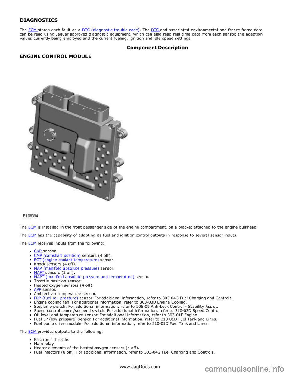
ENGINE CONTROL MODULE Component Description
The ECM is installed in the front passenger side of the engine compartment, on a bracket attached to the engine bulkhead. The ECM has the capability of adapting its fuel and ignition control outputs in response to several sensor inputs. The ECM receives inputs from the following:
CKP sensor. CMP (camshaft position) sensors (4 off).
ECT (engine coolant temperature) sensor.
Knock sensors (4 off).
MAP (manifold absolute pressure) sensor.
MAFT sensors (2 off). MAPT (manifold absolute pressure and temperature) sensor.
Throttle position sensor.
Heated oxygen sensors (4 off).
APP sensor. Ambient air temperature sensor.
FRP (fuel rail pressure) sensor. For additional information, refer to 303-04G Fuel Charging and Controls.
Engine cooling fan. For additional information, refer to 303-03D Engine Cooling.
Stoplamp switch. For additional information, refer to 206-09 Anti-Lock Control - Stability Assist.
Speed control cancel/suspend switch. For additional information, refer to 310-03D Speed Control.
Oil level and temperature sensor. For additional information, refer to 303-01F Engine.
Fuel LP (low pressure) sensor. For additional information, refer to 310-01D Fuel Tank and Lines.
Fuel pump driver module. For additional information, refer to 310-01D Fuel Tank and Lines.
The ECM provides outputs to the following: Electronic throttle.
Main relay.
Heater elements of the heated oxygen sensors (4 off).
Fuel injectors (8 off). For additional information, refer to 303-04G Fuel Charging and Controls. www.JagDocs.com
Page 1373 of 3039

DTC Description Possible Causes Action B10AC-81
Cruise Control Switch -
invalid serial data received
The Engine Control Module
(ECM) has received an invalid
command from the steering
wheel switch pack Clear the DTC and press all the steering wheel
switches, re-check for DTCs. Refer to the
electrical circuit diagrams and check the Cruise
control switch circuit for open circuit, short to
power, short to ground, disconnected. Check
and install a new Steering Wheel Module (SWM) as required. B10AC-82 Cruise Control Switch - alive / sequence counter incorrect / not updated
Cruise Buttons alive counter is
not incrementing. Which
suggests that the LIN bus is
faulty
Steering Wheel Module (SWM) is
not connected
Steering Wheel Module (SWM)
failure Refer to the electrical circuit diagrams and
check the Cruise control switch circuit for open
circuit, short to power, short to ground,
disconnected. Check and install a new Steering
Wheel Module (SWM) as required. B10AC-83
Cruise Control Switch - value
of signal protection
calculation incorrect
Cruise buttons checksum
incorrect, incorrect cruise
switches fitted to vehicle Check and install new cruise switches as
required. B10AC-96
Cruise Control Switch -
component internal failure
Cruise control switch circuit,
open circuit, short to power,
short to ground, disconnected
Cruise Control Switch failure
Steering Wheel Module (SWM)
failure Check for related DTCs in other Central
Junction Box (CJB)s. Refer to the electrical
circuit diagrams and check the Cruise control
switch circuit for open circuit, short to power,
short to ground, disconnected. Check and
install a new cruise control switch as required.
Check and install a new Steering Wheel
Module (SWM) as required. B10FF-68
Ignition Control - Event
information
Spark plug(s) fault
Wiring harness fault
Ignition coil(s) fault Refer to repair manual and check spark plug(s)
for condition and security. Replace any
defective components as required. Refer to
electrical wiring diagrams and check ignition
coil circuit for intermittent open circuit, short
to power, short to ground. Check and install a
new coil(s) as required. B11DB-01
Battery Monitoring Module -
General Electrical Failure
Charging system fault Battery
monitoring signal line
circuit fault
Vehicle battery fault Refer to electrical wiring diagrams and check
charging system for faults. Perform any repairs
required. Refer to the electrical wiring
diagrams and check the Battery Monitoring
System (BMS) module circuit for open circuit,
short to ground, short to power. Refer to the
battery care manual and check and install a
new battery. B11DB-87
Battery Monitoring Module -
missing message
Battery signal line circuit fault Refer to the electrical wiring diagrams and
check the Battery Monitoring System (BMS)
module circuit for open circuit, short to ground,
short to power. B1206-68
Crash Occurred - event
information
Engine control Module (ECM) has
detected the vehicle has crashed
- event information DTC only Refer to the electrical circuit diagrams and
check the Engine Control Module (ECM) to
Restraints Control Module (RCM) circuit for
short to ground, short to power, open circuit.
Repair circuit as required, clear DTC and retest
system to confirm repair. C0031-00
Left Front Wheel Speed
Sensor - No sub type
information
Invalid data received from
Anti-lock Braking System (ABS)
module - left front wheel speed
signal fault Check Anti-lock Braking System (ABS) module
for related DTCs and refer to relevant DTC
Index. C0034-00
Right Front Wheel Speed
Sensor - No sub type
information
Invalid data received from
Anti-lock Braking System (ABS)
module - right front wheel speed
signal fault Check Anti-lock Braking System (ABS) module
for related DTCs and refer to relevant DTC
Index. C0037-00
Left Rear Wheel Speed
Sensor - No sub type
information
Invalid data received from
Anti-lock Braking System (ABS)
module - left rear wheel speed
signal fault Check Anti-lock Braking System (ABS) module
for related DTCs and refer to relevant DTC
Index. C003A-00
Right Rear Wheel Speed
Sensor - No sub type
information
Invalid data received from
Anti-lock Braking System (ABS)
module - right rear wheel speed
signal fault Check Anti-lock Braking System (ABS) module
for related DTCs and refer to relevant DTC
Index.
Page 1376 of 3039
Published: 11-May-2011
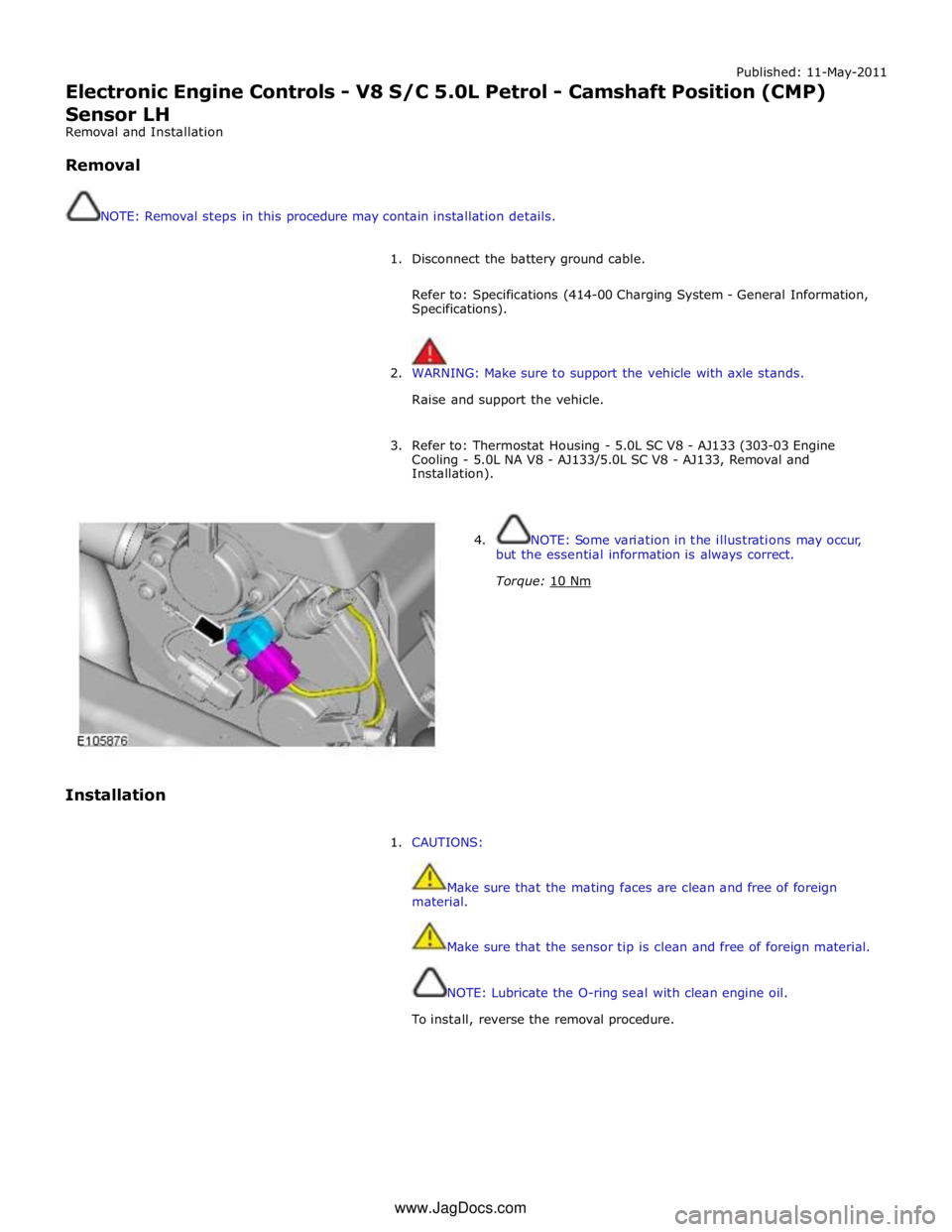
Electronic Engine Controls - V8 S/C 5.0L Petrol - Camshaft Position (CMP)
Sensor LH
Removal and Installation
Removal
NOTE: Removal steps in this procedure may contain installation details.
1. Disconnect the battery ground cable.
Refer to: Specifications (414-00 Charging System - General Information,
Specifications).
2. WARNING: Make sure to support the vehicle with axle stands.
Raise and support the vehicle.
3. Refer to: Thermostat Housing - 5.0L SC V8 - AJ133 (303-03 Engine
Cooling - 5.0L NA V8 - AJ133/5.0L SC V8 - AJ133, Removal and
Installation).
Installation
4. NOTE: Some variation in the illustrations may occur,
but the essential information is always correct.
Torque: 10 Nm
1. CAUTIONS:
Make sure that the mating faces are clean and free of foreign
material.
Make sure that the sensor tip is clean and free of foreign material.
NOTE: Lubricate the O-ring seal with clean engine oil.
To install, reverse the removal procedure. www.JagDocs.com
Page 1377 of 3039
Published: 11-May-2011
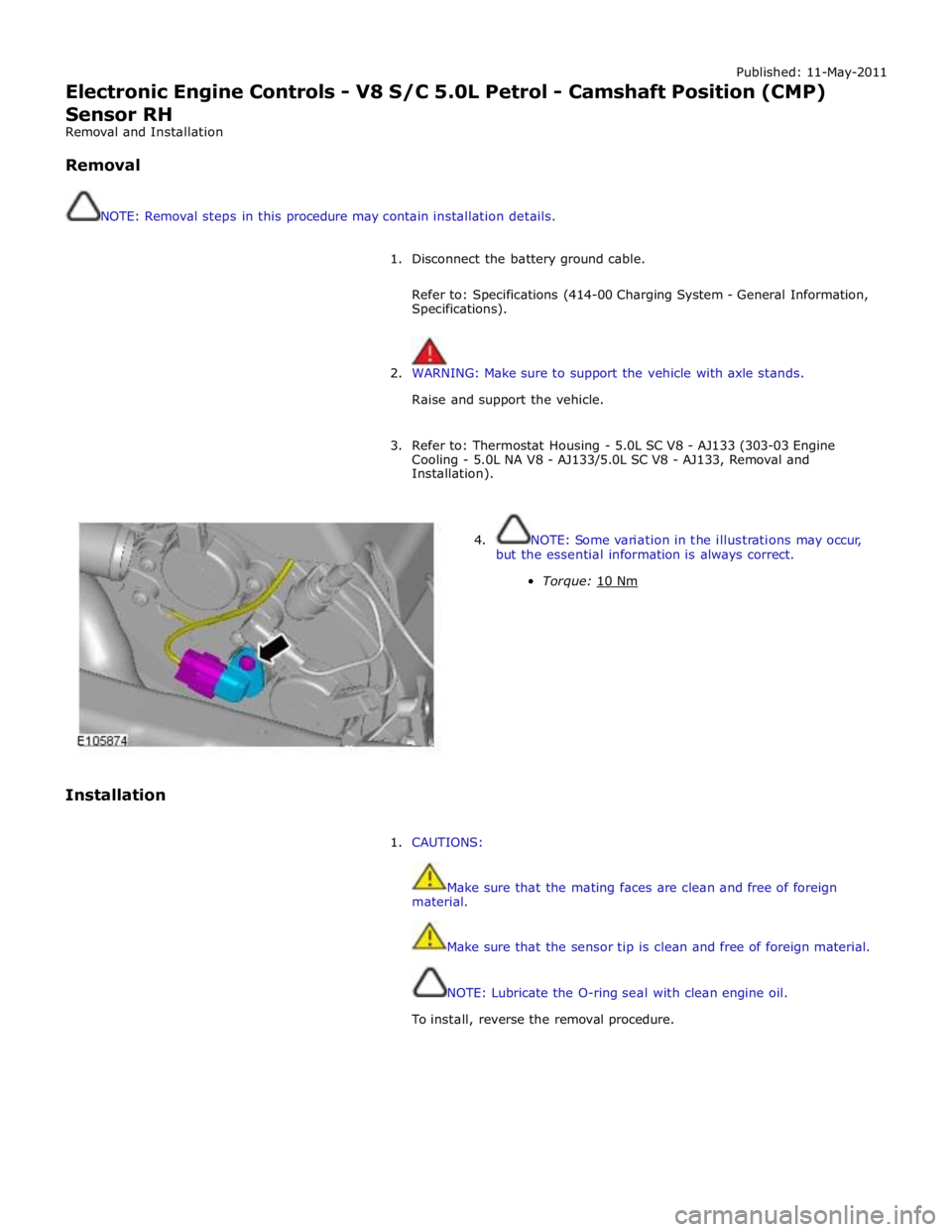
Electronic Engine Controls - V8 S/C 5.0L Petrol - Camshaft Position (CMP)
Sensor RH
Removal and Installation
Removal
NOTE: Removal steps in this procedure may contain installation details.
1. Disconnect the battery ground cable.
Refer to: Specifications (414-00 Charging System - General Information,
Specifications).
2. WARNING: Make sure to support the vehicle with axle stands.
Raise and support the vehicle.
3. Refer to: Thermostat Housing - 5.0L SC V8 - AJ133 (303-03 Engine
Cooling - 5.0L NA V8 - AJ133/5.0L SC V8 - AJ133, Removal and
Installation).
Installation
4. NOTE: Some variation in the illustrations may occur,
but the essential information is always correct.
Torque: 10 Nm
1. CAUTIONS:
Make sure that the mating faces are clean and free of foreign
material.
Make sure that the sensor tip is clean and free of foreign material.
NOTE: Lubricate the O-ring seal with clean engine oil.
To install, reverse the removal procedure.
Page 1426 of 3039
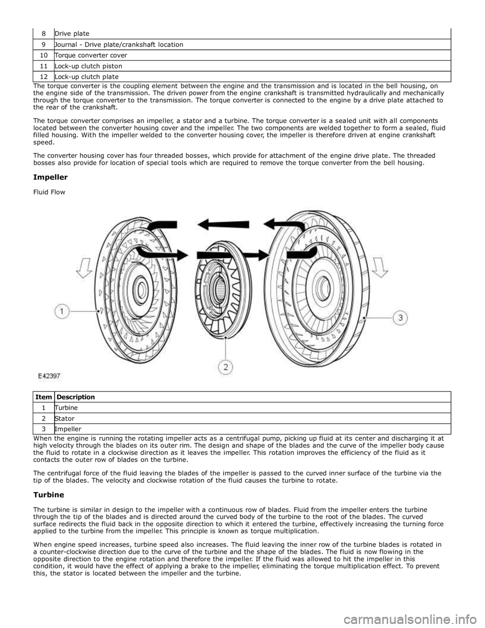
9 Journal - Drive plate/crankshaft location 10 Torque converter cover 11 Lock-up clutch piston 12 Lock-up clutch plate The torque converter is the coupling element between the engine and the transmission and is located in the bell housing, on
the engine side of the transmission. The driven power from the engine crankshaft is transmitted hydraulically and mechanically
through the torque converter to the transmission. The torque converter is connected to the engine by a drive plate attached to
the rear of the crankshaft.
The torque converter comprises an impeller, a stator and a turbine. The torque converter is a sealed unit with all components
located between the converter housing cover and the impeller. The two components are welded together to form a sealed, fluid
filled housing. With the impeller welded to the converter housing cover, the impeller is therefore driven at engine crankshaft
speed.
The converter housing cover has four threaded bosses, which provide for attachment of the engine drive plate. The threaded
bosses also provide for location of special tools which are required to remove the torque converter from the bell housing.
Impeller
Fluid Flow
Item Description 1 Turbine 2 Stator 3 Impeller When the engine is running the rotating impeller acts as a centrifugal pump, picking up fluid at its center and discharging it at
high velocity through the blades on its outer rim. The design and shape of the blades and the curve of the impeller body cause
the fluid to rotate in a clockwise direction as it leaves the impeller. This rotation improves the efficiency of the fluid as it
contacts the outer row of blades on the turbine.
The centrifugal force of the fluid leaving the blades of the impeller is passed to the curved inner surface of the turbine via the
tip of the blades. The velocity and clockwise rotation of the fluid causes the turbine to rotate.
Turbine
The turbine is similar in design to the impeller with a continuous row of blades. Fluid from the impeller enters the turbine
through the tip of the blades and is directed around the curved body of the turbine to the root of the blades. The curved
surface redirects the fluid back in the opposite direction to which it entered the turbine, effectively increasing the turning force
applied to the turbine from the impeller. This principle is known as torque multiplication.
When engine speed increases, turbine speed also increases. The fluid leaving the inner row of the turbine blades is rotated in
a counter-clockwise direction due to the curve of the turbine and the shape of the blades. The fluid is now flowing in the
opposite direction to the engine rotation and therefore the impeller. If the fluid was allowed to hit the impeller in this
condition, it would have the effect of applying a brake to the impeller, eliminating the torque multiplication effect. To prevent
this, the stator is located between the impeller and the turbine.
Page 1436 of 3039
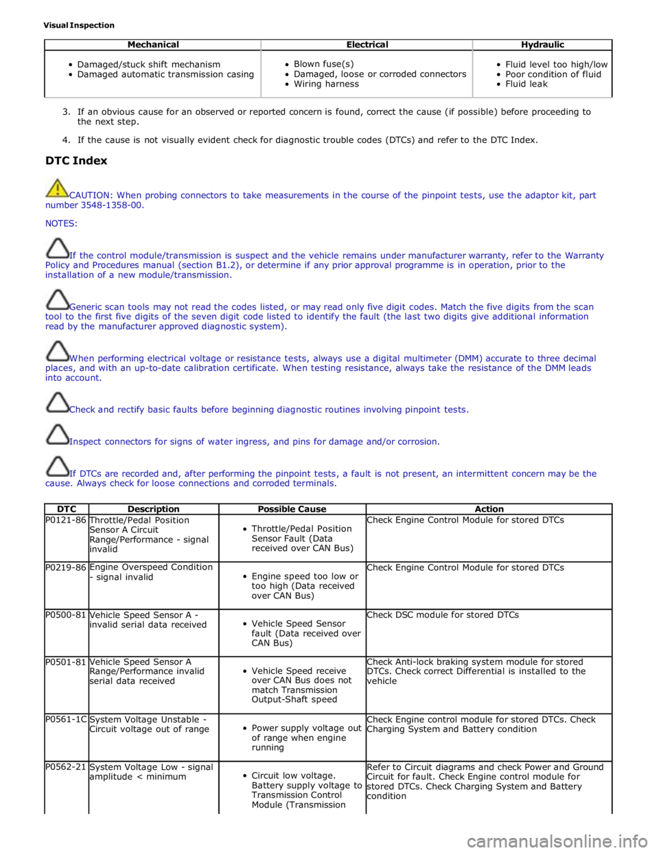
Visual Inspection
Mechanical Electrical Hydraulic
Damaged/stuck shift mechanism
Damaged automatic transmission casing
Blown fuse(s)
Damaged, loose or corroded connectors
Wiring harness
Fluid level too high/low
Poor condition of fluid
Fluid leak
3. If an obvious cause for an observed or reported concern is found, correct the cause (if possible) before proceeding to
the next step.
4. If the cause is not visually evident check for diagnostic trouble codes (DTCs) and refer to the DTC Index.
DTC Index
CAUTION: When probing connectors to take measurements in the course of the pinpoint tests, use the adaptor kit, part
number 3548-1358-00.
NOTES:
If the control module/transmission is suspect and the vehicle remains under manufacturer warranty, refer to the Warranty
Policy and Procedures manual (section B1.2), or determine if any prior approval programme is in operation, prior to the
installation of a new module/transmission.
Generic scan tools may not read the codes listed, or may read only five digit codes. Match the five digits from the scan
tool to the first five digits of the seven digit code listed to identify the fault (the last two digits give additional information
read by the manufacturer approved diagnostic system).
When performing electrical voltage or resistance tests, always use a digital multimeter (DMM) accurate to three decimal
places, and with an up-to-date calibration certificate. When testing resistance, always take the resistance of the DMM leads
into account.
Check and rectify basic faults before beginning diagnostic routines involving pinpoint tests.
Inspect connectors for signs of water ingress, and pins for damage and/or corrosion.
If DTCs are recorded and, after performing the pinpoint tests, a fault is not present, an intermittent concern may be the
cause. Always check for loose connections and corroded terminals.
DTC Description Possible Cause Action P0121-86 Throttle/Pedal Position
Sensor A Circuit
Range/Performance - signal
invalid
Throttle/Pedal Position
Sensor Fault (Data
received over CAN Bus) Check Engine Control Module for stored DTCs P0219-86 Engine Overspeed Condition
- signal invalid
Engine speed too low or
too high (Data received
over CAN Bus) Check Engine Control Module for stored DTCs P0500-81
Vehicle Speed Sensor A -
invalid serial data received
Vehicle Speed Sensor
fault (Data received over
CAN Bus) Check DSC module for stored DTCs P0501-81 Vehicle Speed Sensor A
Vehicle Speed receive Check Anti-lock braking system module for stored Range/Performance invalid DTCs. Check correct Differential is installed to the serial data received over CAN Bus does not
vehicle match Transmission Output-Shaft speed P0561-1C
System Voltage Unstable -
Circuit voltage out of range
Power supply voltage out
of range when engine
running Check Engine control module for stored DTCs. Check
Charging System and Battery condition P0562-21
System Voltage Low - signal
amplitude < minimum
Circuit low voltage.
Battery supply voltage to
Transmission Control
Module (Transmission Refer to Circuit diagrams and check Power and Ground
Circuit for fault. Check Engine control module for
stored DTCs. Check Charging System and Battery
condition
Page 1437 of 3039

DTC Description Possible Cause Action control module)
P0563-22
System Voltage High - signal
amplitude > maximum
High Battery charge,
alternator fault Check Engine control module for stored DTCs. Check
Charging System and Battery condition P0601-41
Internal Control Module
Memory Check Sum Error -
general checksum failure
Software error
Transmission control
module failure Re-configure the Transmission control module using
the manufacturer approved diagnostic system, clear
DTC and re-test. If DTC remains, Suspect the
Transmission control module. Install a new
Transmission control module as required, refer to the
new module/component installation note at the top of
the DTC Index P0604-00
Internal Control Module
Random Access Memory
(RAM) Error - no sub type
information
Shift-by-Wire fault Suspect the Transmission control module. Install a
new Transmission control module as required, refer to
the new module/component installation note at the top of the DTC Index P0605-41
Internal Control Module
Read Only Memory (ROM)
Error - general checksum
failure
General checksum failure Suspect the Transmission control module. Install a
new Transmission control module as required, refer to
the new module/component installation note at the top of the DTC Index P0606-04 Transmission control module
Processor - System Internal
Failures
Micro controller
component faults Suspect the Transmission control module. Install a
new Transmission control module as required, refer to
the new module/component installation note at the top of the DTC Index P0606-26 Transmission control module
Processor - signal rate of
change below threshold
Micro controller
component faults Suspect the Transmission control module. Install a
new Transmission control module as required, refer to
the new module/component installation note at the top of the DTC Index P0606-49 Transmission control module
Processor-internal electronic
failure
Micro controller
component faults Suspect the Transmission control module. Install a
new Transmission control module as required, refer to
the new module/component installation note at the top of the DTC Index P0613-04 Transmission control module
Processor - System Internal
Failures
Micro controller
component faults Suspect the Transmission control module. Install a
new Transmission control module as required, refer to
the new module/component installation note at the top of the DTC Index P0613-06 Transmission control module
Processor - Algorithm Based
Failures
Micro controller
component faults Suspect the Transmission control module. Install a
new Transmission control module as required, refer to
the new module/component installation note at the top of the DTC Index P0613-11 Transmission control module
Processor - Circuit Short to
Ground
Watchdog fault Suspect the Transmission control module. Install a
new Transmission control module as required, refer to
the new module/component installation note at the top of the DTC Index P0613-12 Transmission control module
Processor - Circuit Short to
Battery
Watchdog fault Suspect the Transmission control module. Install a
new Transmission control module as required, refer to
the new module/component installation note at the top of the DTC Index P0613-13 Transmission control module
Processor - Circuit Open
Watchdog fault Suspect the Transmission control module. Install a
new Transmission control module as required, refer to
the new module/component installation note at the top of the DTC Index P0613-14 Transmission control module
Processor - Circuit Short to
Ground or Open
Watchdog fault Suspect the Transmission control module. Install a
new Transmission control module as required, refer to
the new module/component installation note at the top of the DTC Index P0613-21 Transmission control module
Processor - signal amplitude
< minimum
Watchdog fault Suspect the Transmission control module. Install a
new Transmission control module as required, refer to
the new module/component installation note at the top of the DTC Index P0613-22 Transmission control module
Processor - signal amplitude
> maximum
Watchdog fault Suspect the Transmission control module. Install a
new Transmission control module as required, refer to
the new module/component installation note at the top of the DTC Index P0613-47 Transmission control module
Processor - watchdog /
safety Micro controller
failure
Watchdog fault Suspect the Transmission control module. Install a
new Transmission control module as required, refer to
the new module/component installation note at the top of the DTC Index P0613-49 Transmission control module
Processor - internal
electronic failure
Micro controller
component faults Suspect the Transmission control module. Install a
new Transmission control module as required, refer to
the new module/component installation note at the top of the DTC Index P0613-68 Transmission control module
Processor-Event Information
Watchdog fault Suspect the Transmission control module. Install a
new Transmission control module as required, refer to
the new module/component installation note at the top of the DTC Index www.JagDocs.com