2010 JAGUAR XFR charging
[x] Cancel search: chargingPage 237 of 3039

DTC Description Possible Causes Action B1A89-12
Satellite Antenna -
Circuit short to
battery
Satellite antenna circuit -
short to power
Refer to the electrical circuit diagrams and check
satellite antenna circuit for short circuit to power. Repair
wiring harness as required. Clear DTC and retest B1A89-13
Satellite Antenna -
Circuit open
Satellite antenna circuit -
open circuit, high
resistance
Refer to the electrical circuit diagrams and check
satellite antenna circuit for open circuit, high
resistance. Repair wiring harness as required. Clear DTC
and retest U3000-04
Control Module -
System internal
failures
System internal failure
Check and install a new satellite radio module as
required. Refer to the warranty policy and procedures
manual, or determine if any prior approval programme is
in operation, prior to the installation of a new
module/component U3000-4A Control Module -
Satellite radio module -
Using the manufacturer approved diagnostic system Incorrect component Incorrect component select the vehicle configuration main menu>vehicle installed installed configuration>display and modify the vehicle Car configuration configuration file data mismatch Check update as required U3000-55
Control Module -
Not configured
Satellite radio module -
Incorrect component
installed
Incorrect car configuration
file data received
Using the manufacturer approved diagnostic system
select the vehicle configuration main menu>select
configure existing modules menu and program the
satellite radio module U3000-87
Control Module -
Missing message
The satellite radio module
has not received the
configuration file
Master module not
transmitting configuration
file
Using the manufacturer approved diagnostic system
check that the satellite radio module is configured
correctly
Check that the configuration file is being transmitted by
the master module
Using the manufacturer approved diagnostic system,
complete a MOST network integrity test U3000-98
Control Module -
Component or
system over
temperature
Satellite radio module
cooling vents obstructed
Wiring harness fault
Internal electronic failure
Check for possible causes of the satellite radio module
overheating. Check that the ventilation is not
obstructed
Check for short circuit related DTCs. Refer to the
electrical circuit diagrams and check ground circuit for
high resistance. Check antenna circuit for short to power
or ground. Repair wiring harness as required. Clear DTC
and retest
Check for internal electronic failure related DTCs
If fault persists, check and install a new satellite radio
module. Refer to the warranty policy and procedures
manual, or determine if any prior approval programme is
in operation, prior to the installation of a new
module/component U3003-62
Battery Voltage -
Signal compare
failure
Signal compare failure
Satellite radio module
voltage differs more than
±2V compared to rear
junction box voltage
Refer to relevant section of workshop manual and
battery care manual. Check battery state of charge and
starting/charging system performance. Check power
supply circuit from rear junction box to satellite radio
module
Refer to electrical circuit diagrams and check the power
and ground supply circuits to the module. Repair wiring
harness as required. Clear DTC and retest
Page 240 of 3039

DTC Description Possible Causes Action U0300-00
Internal Control Module
Software
Incompatibility - No
sub type information
Invalid configuration
message is received
Re-configure the speed control module using the
manufacturer approved diagnostic system. Clear
DTCs and re-test. If DTC still logged, suspect
incorrect speed control module installed. Check and
install a new module as required, refer to new
module/component installation note at top of DTC
Index U0300-55
Internal Control Module
Software
Incompatibility - Not
configured
RJB - at least one of the
car configuration
parameters is not
configured
Re-configure the RJB using the manufacturer
approved diagnostic system U0401-00
Invalid Data Received
From ECM/PCM A - No
sub type information
ECM did not respond
properly to speed control
cancel or auto brake
cancel request
Check ECM for related DTCs and refer to relevant
DTC Index U0401-67
Invalid Data Received
From ECM/PCM A -
Signal incorrect after
event
ECM did not respond
properly to speed control
resume request
Check ECM for related DTCs and refer to relevant
DTC Index U0401-81
Invalid Data Received
From ECM/PCM A -
Invalid serial data
received
Invalid data received
from engine control
module
Bus signal/message
failure
Speed control inhibited
by ECM
Check the Engine Control Module for related DTCs
and refer to relevant DTC Index. If U040181 is
logged as historic but no other DTCs have logged in
the engine control module at the same time and
distance, it may be caused by cranking with low
voltage conditions. Check battery and charging
system according to instructions in the battery care
manual. Install the latest Engine Control Module
software using the manufacturer approved diagnostic
system, contact Dealer Technical Support before
replacing components U0415-53
Invalid Data Received
From Anti-Lock Braking
System (ABS) Control
Module - De-activated
Event information
Deactivated
Check the Anti-Lock Braking System Module for
related DTCs and refer to the relevant DTC index U0415-81
Invalid Data Received
From Anti-lock Brake
System (ABS) Control
Module - Invalid serial
data received
Stability assist fault
Check ABS module for related DTCs and refer to
relevant DTC Index U0417-67
Invalid Data Received
From Park Brake
Control Module - Signal
incorrect after event
Parking brake module did
not respond properly to
apply request
Check parking brake module for related DTCs and
refer to relevant DTC Index U0417-81
Invalid Data Received
From Park Brake
Control Module -
Invalid serial data
received
Speed control inhibited
by parking brake module
Check parking brake module for related DTCs and
refer to relevant DTC Index U0418-68
Invalid Data Received
From Brake System
Control Module - Event
information
Event information
Check the Anti-Lock Braking System Module for
related DTCs and refer to the relevant DTC index U0421-81
Invalid Data Received
From Suspension
Control Module 'A' -
Invalid serial data
received
Invalid serial data
received
Check the Suspension Control Module for related
DTCs and refer to the relevant DTC index U0423-81
Invalid Data Received
From Instrument Panel
Control Module -
Invalid serial data
received
Speed control inhibited
by instrument cluster
Check instrument cluster, CJB and RJB for related
DTCs and refer to relevant DTC Index U1A00-88
Private Communication
Network - Bus off
Bus off
The module setting this code has disabled CAN
transmission. Check for other bus off codes. Check
the module and circuits. Refer to the electrical circuit
diagrams. Clear all DTCs and road test the vehicle. If
the concern reoccurs contact Dealer Technical
Page 241 of 3039

DTC Description Possible Causes Action Support for further advice. Under no circumstance
should any parts be replaced to overcome this issue U1A14-49
CAN Initialisation
Failure - Internal
electronic failure
Internal electronic failure
Suspect the speed control module. Check and install
a new module as required, refer to the new
module/component installation note at the top of
the DTC Index U2101-00
Control Module
Configuration
Incompatible - No sub
type information
Data sent from RJB is
invalid
Check/amend Car Configuration File using the
manufacturer approved diagnostic system, clear DTC
and re-test. If DTC remains, re-configure RJB using
manufacturer approved diagnostic system, clear DTC
and re-test. If DTC remains check RJB for DTCs and
refer to DTC Index U3000-41
Control Module -
General checksum
failure
Internal micro controller
error
Checksum fault
Suspect the speed control module. Check and install
a new module as required, refer to the new
module/component installation note at the top of
the DTC Index U3000-42
Control Module -
General memory failure
Internal RAM test fault
Suspect the speed control module. Check and install
a new module as required, refer to the new
module/component installation note at the top of
the DTC Index U3000-49
Control Module -
Internal electronic
failure
Internal control module
failure
Suspect the speed control module. Check and install
a new module as required, refer to the new
module/component installation note at the top of
the DTC Index U3000-63
Control Module -
Circuit/component
protection time-out
Circuit/component
protection time-out
The Control module internal protection has been
activated. Check for other related DTCs that could
lead to this event. Clear the DTC and retest. If the
problem persists, renew the module. Refer to the
warranty policy and procedures manual if a module is
suspect U3003-62
Battery Voltage -
Signal compare failure
Signal compare failure
Battery supply voltage
below a recognized value
Check vehicle battery and charging system. Refer to
the relevant section in the workshop manual. Refer
to the electrical circuit diagrams and check the power
and ground supply circuits to the modules www.JagDocs.com
Page 254 of 3039

DTC Description Possible Causes Action P0561-1C System Voltage Unstable
- Circuit voltage out of
range
Power supply voltage out
of range when engine
running
Check Engine Control Module for stored DTCs.
Check Charging System and Battery condition P0562-21
System Voltage Low -
Signal amplitude <
minimum
Circuit low voltage.
Battery supply voltage to
Transmission Control
Module
Refer to Circuit diagrams and check Power and
Ground Circuit for fault. Check Engine Control
Module for stored DTCs. Check Charging System
and Battery condition P0563-22
System Voltage High -
Signal amplitude >
maximum
High Battery charge,
alternator fault
Check Engine Control Module for stored DTCs.
Check Charging System and Battery condition P0601-41
Internal Control Module
Memory Check Sum Error
- General checksum
failure
Software error
Transmission Control
Module failure
Re-configure the Transmission Control Module
using the manufacturer approved diagnostic
system, clear DTC and re-test. If DTC remains,
Suspect the Transmission Control Module. Install a
new Transmission Control Module as required,
refer to the warranty policy and procedures manual
if a module/component is suspect. P0604-00
Internal Control Module
Random Access Memory
(RAM) Error - No sub type
information
Shift-by-Wire fault
Suspect the Transmission Control Module. Install a
new Transmission Control Module as required,
refer to the warranty policy and procedures manual
if a module/component is suspect. P0605-41
Internal Control Module
Read Only Memory (ROM)
Error - General checksum
failure
General checksum failure
Suspect the Transmission Control Module. Install a
new Transmission Control Module as required,
refer to the warranty policy and procedures manual
if a module/component is suspect. P0606-04 TCM Processor - System
Internal Failures
Micro controller
component faults
Suspect the Transmission Control Module. Install a
new Transmission Control Module as required,
refer to the warranty policy and procedures manual
if a module/component is suspect. P0606-26 TCM Processor - Signal
rate of change below
threshold
Micro controller
component faults
Suspect the Transmission Control Module. Install a
new Transmission Control Module as required,
refer to the warranty policy and procedures manual
if a module/component is suspect. P0606-49 TCM Processor - Internal
electronic failure
Micro controller
component faults
Suspect the Transmission Control Module. Install a
new Transmission Control Module as required,
refer to the warranty policy and procedures manual
if a module/component is suspect. P0613-04 TCM Processor - System
Internal Failures
Micro controller
component faults
Suspect the Transmission Control Module. Install a
new Transmission Control Module as required,
refer to the warranty policy and procedures manual
if a module/component is suspect. P0613-06 TCM Processor -
Algorithm Based Failures
Micro controller
component faults
Suspect the Transmission Control Module. Install a
new Transmission Control Module as required,
refer to the warranty policy and procedures manual
if a module/component is suspect. P0613-11 TCM Processor - Circuit
Short to Ground
Watchdog fault
Suspect the Transmission Control Module. Install a
new Transmission Control Module as required,
refer to the warranty policy and procedures manual
if a module/component is suspect. P0613-12 TCM Processor - Circuit
Short to Battery
Watchdog fault
Suspect the Transmission Control Module. Install a
new Transmission Control Module as required,
refer to the warranty policy and procedures manual
if a module/component is suspect.
Page 356 of 3039

Published: 06-Jun-2013
Front Suspension - Front Stabilizer Bar V8 5.0L Petrol/V8 S/C 5.0L Petrol
Removal and Installation
Removal
NOTE: Removal steps in this procedure may contain installation details.
1. Refer to: Battery Disconnect and Connect (414-01 Battery, Mounting and Cables, General Procedures).
2. WARNING: Do not work on or under a vehicle supported only by a jack.
Always support the vehicle on safety stands.
Raise and support the vehicle.
3. Refer to: Air Conditioning (A/C) System Recovery, Evacuation and Charging (412-00 Climate Control System - General Information, General Procedures).
4. Refer to: Radiator Splash Shield (501-02 Front End Body Panels, Removal and Installation).
5. Refer to: Air Deflector (501-02 Front End Body Panels, Removal and Installation).
6. Refer to: Front Wheel Bearing and Wheel Hub - TDV6 3.0L Diesel /V8 5.0L Petrol/V8 S/C 5.0L Petrol (204-01 Front Suspension, Removal and Installation).
7. Refer to: Engine Cover - V8 5.0L Petrol/V8 S/C 5.0L Petrol (501-05 Interior Trim and Ornamentation, Removal and Installation).
8.
Secure the radiator assembly. 303-021
Engine support bracket Special Tool(s) www.JagDocs.com
Page 816 of 3039

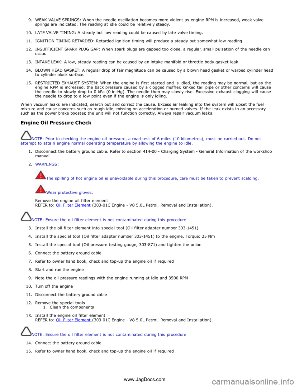
9. WEAK VALVE SPRINGS: When the needle oscillation becomes more violent as engine RPM is increased, weak valve
springs are indicated. The reading at idle could be relatively steady.
10. LATE VALVE TIMING: A steady but low reading could be caused by late valve timing.
11.
IGNITION TIMING RETARDED: Retarded ignition timing will produce a steady but somewhat low reading.
12.
INSUFFICIENT SPARK PLUG GAP: When spark plugs are gapped too close, a regular, small pulsation of the needle can
occur.
13. INTAKE LEAK: A low, steady reading can be caused by an intake manifold or throttle body gasket leak.
14.
BLOWN HEAD GASKET: A regular drop of fair magnitude can be caused by a blown head gasket or warped cylinder head
to cylinder block surface.
15.
RESTRICTED EXHAUST SYSTEM: When the engine is first started and is idled, the reading may be normal, but as the
engine RPM is increased, the back pressure caused by a clogged muffler, kinked tail pipe or other concerns will cause
the needle to slowly drop to 0 kPa (0 in-Hg). The needle then may slowly rise. Excessive exhaust clogging will cause
the needle to drop to a low point even if the engine is only idling.
When vacuum leaks are indicated, search out and correct the cause. Excess air leaking into the system will upset the fuel
mixture and cause concerns such as rough idle, missing on acceleration or burned valves. If the leak exists in an accessory
such as the power brake booster, the unit will not function correctly. Always repair vacuum leaks.
Engine Oil Pressure Check
NOTE: Prior to checking the engine oil pressure, a road test of 6 miles (10 kilometres), must be carried out. Do not
attempt to attain engine normal operating temperature by allowing the engine to idle.
1. Disconnect the battery ground cable. Refer to section 414-00 - Charging System - General Information of the workshop
manual
2. WARNINGS:
The spilling of hot engine oil is unavoidable during this procedure, care must be taken to prevent scalding.
Wear protective gloves.
Remove the engine oil filter element
REFER to: Oil Filter Element (303-01C Engine - V8 5.0L Petrol, Removal and Installation).
NOTE: Ensure the oil filter element is not contaminated during this procedure
3. Install the oil filter element into special tool (Oil filter adapter number 303-1451)
4. Install the special tool (Oil filter adapter number 303-1451) to the engine. Torque: 25 Nm
5. Install the special tool (Oil pressure testing gauge, 303-871) and tighten the union
6. Connect the battery ground cable
7. Refer to owner hand book, check and top-up the engine oil if required
8. Start and run the engine
9. Note the oil pressure readings with the engine running at idle and 3500 RPM
10.
Turn off the engine
11.
Disconnect the battery ground cable
12. Remove the special tools
1. Clean the components
13.
Install the engine oil filter element
REFER to: Oil Filter Element (303-01C Engine - V8 5.0L Petrol, Removal and Installation).
NOTE: Ensure the oil filter element is not contaminated during this procedure
14.
Connect the battery ground cable
15. Refer to owner hand book, check and top-up the engine oil if required
www.JagDocs.com
Page 1058 of 3039

Engine - V8 S/C 5.0L Petrol - Valve Cover LH
Removal and Installation Published: 11-May-2011
Removal
NOTE: Removal steps in this procedure may contain installation details.
1. Refer to: Battery Disconnect and Connect (414-01 Battery, Mounting and Cables, General Procedures).
2. Refer to: Supercharger (303-12D Intake Air Distribution and Filtering - V8 S/C 5.0L Petrol, Removal and Installation).
3. Refer to: Secondary Bulkhead Panel LH - TDV6 3.0L Diesel /V8 5.0L Petrol/V8 S/C 5.0L Petrol (501-02 Front End Body Panels, Removal and Installation).
4. Refer to: Air Cleaner Outlet Pipe LH (303-12D Intake Air Distribution and Filtering - V8 S/C 5.0L Petrol, Removal and Installation).
5. Refer to: Fuel Rail LH (303-04E Fuel Charging and Controls - V8 S/C 5.0L Petrol, Removal and Installation).
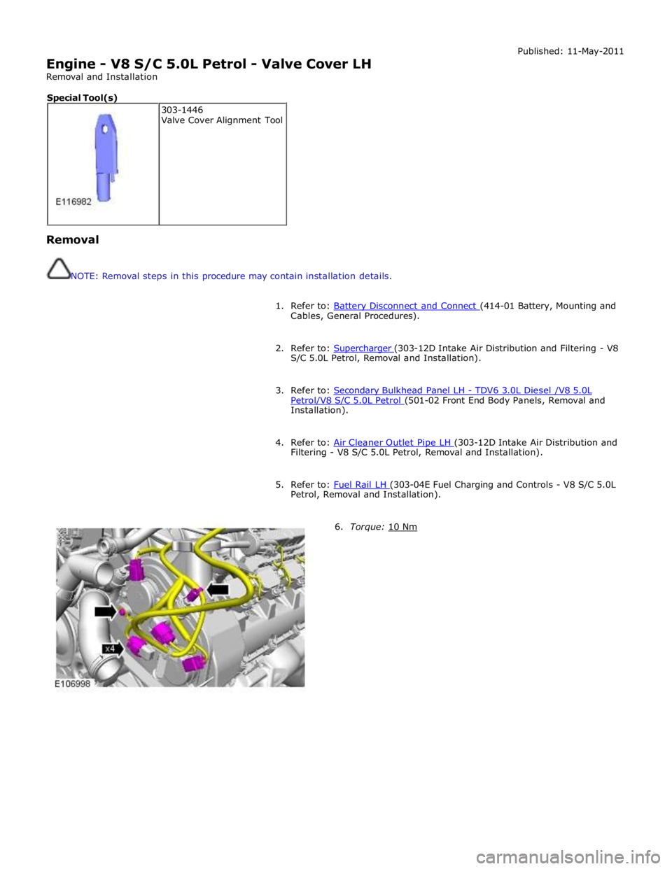
6. Torque: 10 Nm 303-1446
Valve Cover Alignment Tool Special Tool(s)
Page 1061 of 3039

Engine - V8 S/C 5.0L Petrol - Valve Cover RH
Removal and Installation Published: 11-May-2011
Removal
NOTE: Removal steps in this procedure may contain installation details.
1. Refer to: Battery Disconnect and Connect (414-01 Battery, Mounting and Cables, General Procedures).
2. Refer to: Supercharger (303-12D Intake Air Distribution and Filtering - V8 S/C 5.0L Petrol, Removal and Installation).
3. Refer to: Secondary Bulkhead Panel RH - TDV6 3.0L Diesel /V8 5.0L Petrol/V8 S/C 5.0L Petrol (501-02 Front End Body Panels, Removal and Installation).
4. Refer to: Air Cleaner Outlet Pipe RH (303-12D Intake Air Distribution and Filtering - V8 S/C 5.0L Petrol, Removal and Installation).
5. Refer to: Fuel Rail RH (303-04E Fuel Charging and Controls - V8 S/C 5.0L Petrol, Removal and Installation).
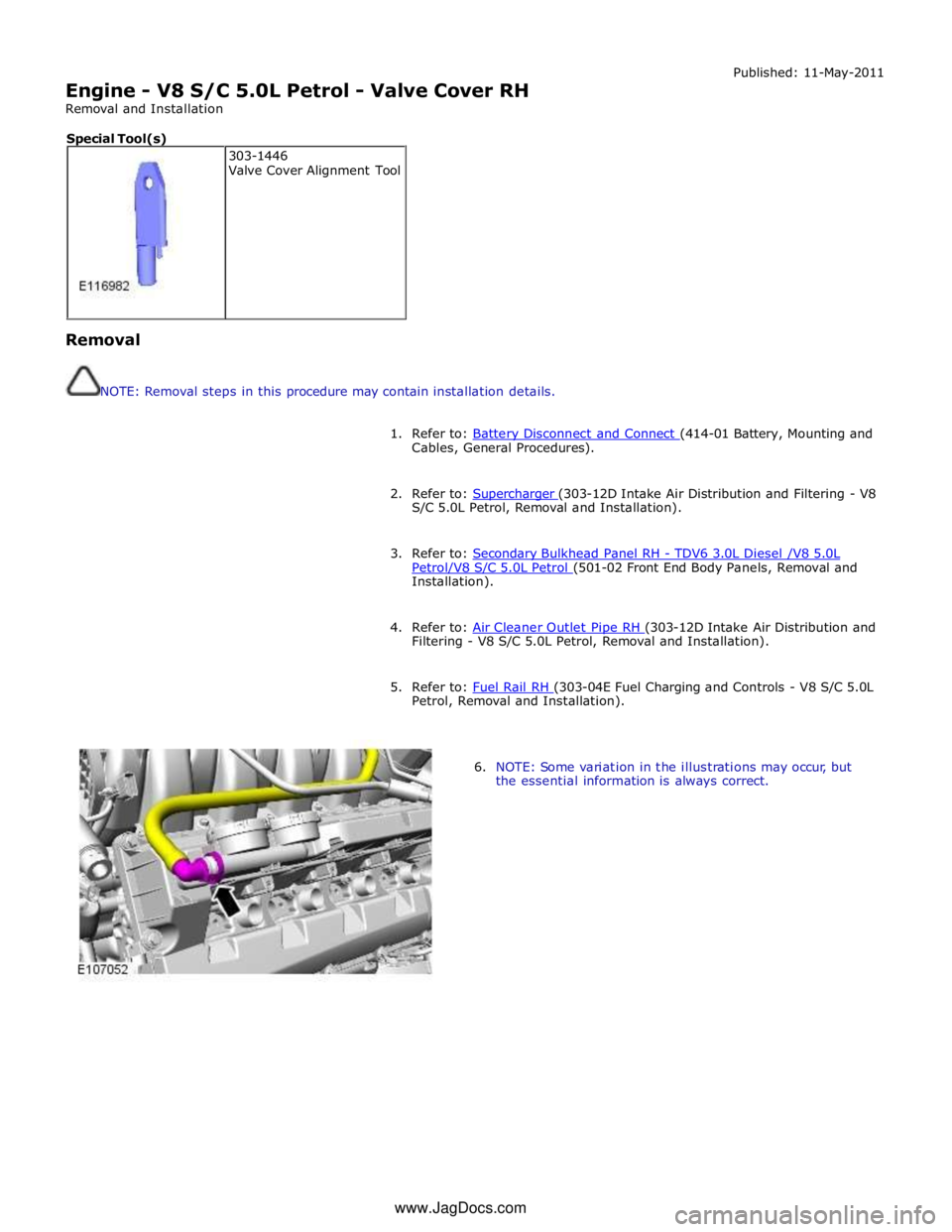
6. NOTE: Some variation in the illustrations may occur, but
the essential information is always correct. 303-1446
Valve Cover Alignment Tool Special Tool(s) www.JagDocs.com