2010 JAGUAR XFR charging
[x] Cancel search: chargingPage 1649 of 3039

DTC Description Possible Causes Action U0401-00
Invalid Data Received
From ECM/PCM A - No
sub type information
ECM did not respond
properly to speed control
cancel or auto brake
cancel request
Check ECM for related DTCs and refer to relevant
DTC Index U0401-67
Invalid Data Received
From ECM/PCM A -
Signal incorrect after
event
ECM did not respond
properly to speed control
resume request
Check ECM for related DTCs and refer to relevant
DTC Index U0401-81
Invalid Data Received
From ECM/PCM A -
Invalid serial data
received
Invalid data received
from engine control
module
Bus signal/message
failure
Speed control inhibited
by ECM
Check the Engine Control Module for related DTCs
and refer to relevant DTC Index. If U040181 is
logged as historic but no other DTCs have logged in
the engine control module at the same time and
distance, it may be caused by cranking with low
voltage conditions. Check battery and charging
system according to instructions in the battery care
manual. Install the latest Engine Control Module
software using the manufacturer approved diagnostic
system, contact Dealer Technical Support before
replacing components U0415-53
Invalid Data Received
From Anti-Lock Braking
System (ABS) Control
Module - De-activated
Event information
Deactivated
Check the Anti-Lock Braking System Module for
related DTCs and refer to the relevant DTC index U0415-81
Invalid Data Received
From Anti-lock Brake
System (ABS) Control
Module - Invalid serial
data received
Stability assist fault
Check ABS module for related DTCs and refer to
relevant DTC Index U0417-67
Invalid Data Received
From Park Brake
Control Module - Signal
incorrect after event
Parking brake module did
not respond properly to
apply request
Check parking brake module for related DTCs and
refer to relevant DTC Index U0417-81
Invalid Data Received
From Park Brake
Control Module -
Invalid serial data
received
Speed control inhibited
by parking brake module
Check parking brake module for related DTCs and
refer to relevant DTC Index U0418-68
Invalid Data Received
From Brake System
Control Module - Event
information
Event information
Check the Anti-Lock Braking System Module for
related DTCs and refer to the relevant DTC index U0421-81
Invalid Data Received
From Suspension
Control Module 'A' -
Invalid serial data
received
Invalid serial data
received
Check the Suspension Control Module for related
DTCs and refer to the relevant DTC index U0423-81
Invalid Data Received
From Instrument Panel
Control Module -
Invalid serial data
received
Speed control inhibited
by instrument cluster
Check instrument cluster, CJB and RJB for related
DTCs and refer to relevant DTC Index U1A00-88
Private Communication
Network - Bus off
Bus off
The module setting this code has disabled CAN
transmission. Check for other bus off codes. Check
the module and circuits. Refer to the electrical circuit
diagrams. Clear all DTCs and road test the vehicle. If
the concern reoccurs contact Dealer Technical
Support for further advice. Under no circumstance
should any parts be replaced to overcome this issue U1A14-49
CAN Initialisation
Failure - Internal
electronic failure
Internal electronic failure
Suspect the speed control module. Check and install
a new module as required, refer to the new
module/component installation note at the top of
the DTC Index U2101-00
Control Module
Configuration
Incompatible - No sub
type information
Data sent from RJB is
invalid
Check/amend Car Configuration File using the
manufacturer approved diagnostic system, clear DTC
and re-test. If DTC remains, re-configure RJB using
manufacturer approved diagnostic system, clear DTC
and re-test. If DTC remains check RJB for DTCs and
Page 1650 of 3039
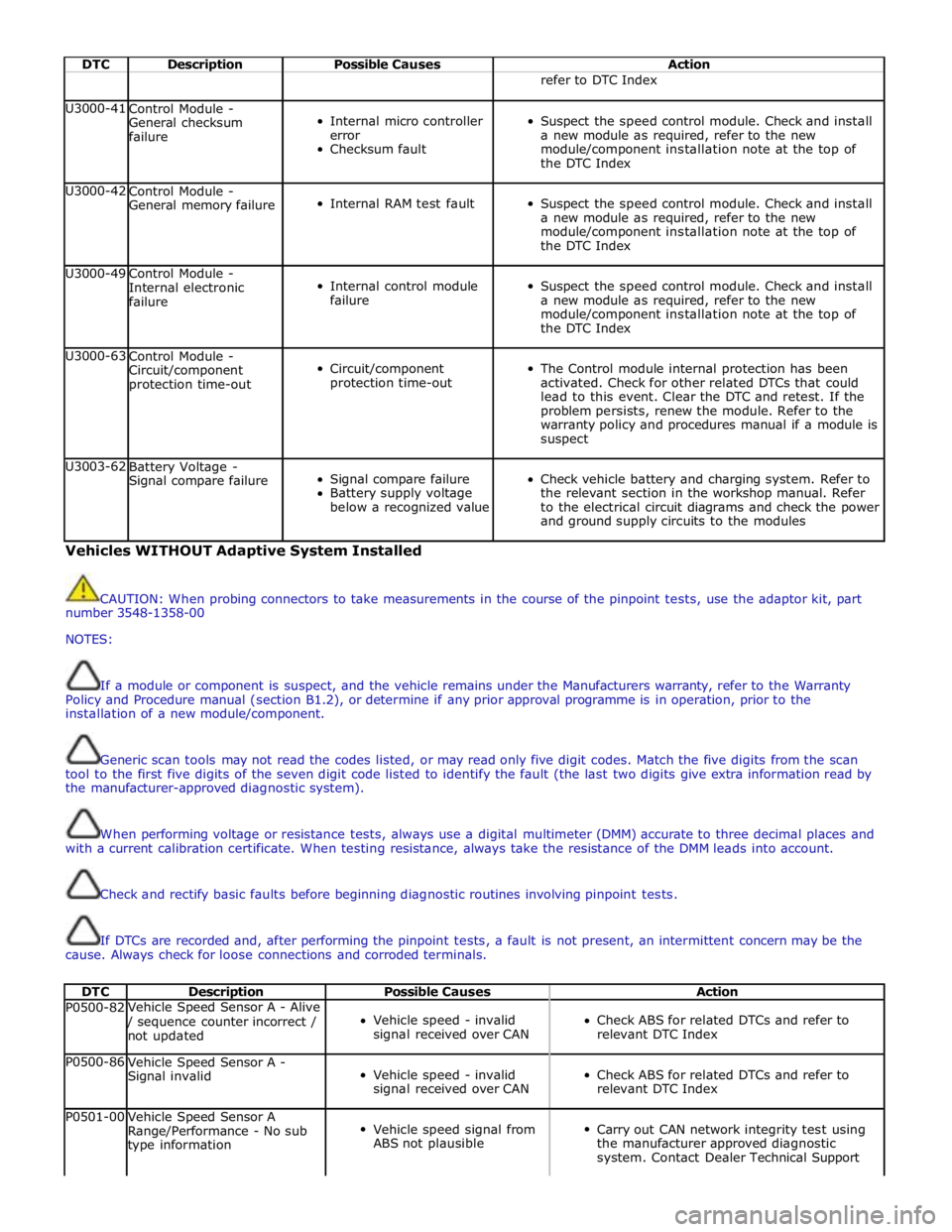
DTC Description Possible Causes Action refer to DTC Index U3000-41
Control Module -
General checksum
failure
Internal micro controller
error
Checksum fault
Suspect the speed control module. Check and install
a new module as required, refer to the new
module/component installation note at the top of
the DTC Index U3000-42
Control Module -
General memory failure
Internal RAM test fault
Suspect the speed control module. Check and install
a new module as required, refer to the new
module/component installation note at the top of
the DTC Index U3000-49
Control Module -
Internal electronic
failure
Internal control module
failure
Suspect the speed control module. Check and install
a new module as required, refer to the new
module/component installation note at the top of
the DTC Index U3000-63
Control Module -
Circuit/component
protection time-out
Circuit/component
protection time-out
The Control module internal protection has been
activated. Check for other related DTCs that could
lead to this event. Clear the DTC and retest. If the
problem persists, renew the module. Refer to the
warranty policy and procedures manual if a module is
suspect U3003-62
Battery Voltage -
Signal compare failure
Signal compare failure
Battery supply voltage
below a recognized value
Check vehicle battery and charging system. Refer to
the relevant section in the workshop manual. Refer
to the electrical circuit diagrams and check the power
and ground supply circuits to the modules Vehicles WITHOUT Adaptive System Installed
CAUTION: When probing connectors to take measurements in the course of the pinpoint tests, use the adaptor kit, part
number 3548-1358-00
NOTES:
If a module or component is suspect, and the vehicle remains under the Manufacturers warranty, refer to the Warranty
Policy and Procedure manual (section B1.2), or determine if any prior approval programme is in operation, prior to the
installation of a new module/component.
Generic scan tools may not read the codes listed, or may read only five digit codes. Match the five digits from the scan
tool to the first five digits of the seven digit code listed to identify the fault (the last two digits give extra information read by
the manufacturer-approved diagnostic system).
When performing voltage or resistance tests, always use a digital multimeter (DMM) accurate to three decimal places and
with a current calibration certificate. When testing resistance, always take the resistance of the DMM leads into account.
Check and rectify basic faults before beginning diagnostic routines involving pinpoint tests.
If DTCs are recorded and, after performing the pinpoint tests, a fault is not present, an intermittent concern may be the
cause. Always check for loose connections and corroded terminals.
DTC Description Possible Causes Action P0500-82 Vehicle Speed Sensor A - Alive / sequence counter incorrect /
not updated
Vehicle speed - invalid
signal received over CAN
Check ABS for related DTCs and refer to
relevant DTC Index P0500-86
Vehicle Speed Sensor A -
Signal invalid
Vehicle speed - invalid
signal received over CAN
Check ABS for related DTCs and refer to
relevant DTC Index P0501-00
Vehicle Speed Sensor A
Range/Performance - No sub
type information
Vehicle speed signal from
ABS not plausible
Carry out CAN network integrity test using
the manufacturer approved diagnostic
system. Contact Dealer Technical Support
Page 1664 of 3039
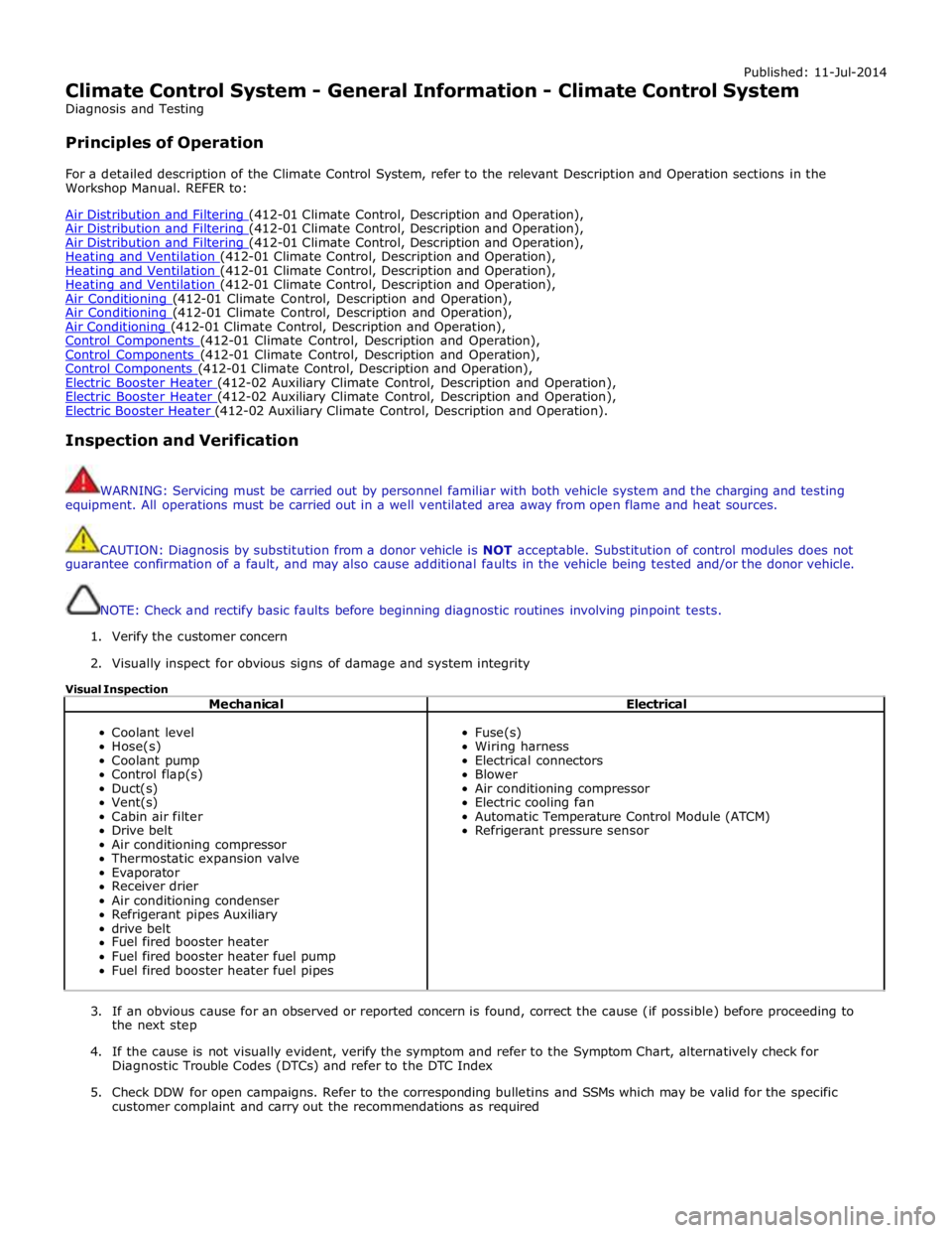
Published: 11-Jul-2014
Climate Control System - General Information - Climate Control System
Diagnosis and Testing
Principles of Operation
For a detailed description of the Climate Control System, refer to the relevant Description and Operation sections in the
Workshop Manual. REFER to:
Air Distribution and Filtering (412-01 Climate Control, Description and Operation), Air Distribution and Filtering (412-01 Climate Control, Description and Operation), Air Distribution and Filtering (412-01 Climate Control, Description and Operation), Heating and Ventilation (412-01 Climate Control, Description and Operation), Heating and Ventilation (412-01 Climate Control, Description and Operation), Heating and Ventilation (412-01 Climate Control, Description and Operation), Air Conditioning (412-01 Climate Control, Description and Operation), Air Conditioning (412-01 Climate Control, Description and Operation), Air Conditioning (412-01 Climate Control, Description and Operation), Control Components (412-01 Climate Control, Description and Operation), Control Components (412-01 Climate Control, Description and Operation), Control Components (412-01 Climate Control, Description and Operation), Electric Booster Heater (412-02 Auxiliary Climate Control, Description and Operation), Electric Booster Heater (412-02 Auxiliary Climate Control, Description and Operation), Electric Booster Heater (412-02 Auxiliary Climate Control, Description and Operation).
Inspection and Verification
WARNING: Servicing must be carried out by personnel familiar with both vehicle system and the charging and testing
equipment. All operations must be carried out in a well ventilated area away from open flame and heat sources.
CAUTION: Diagnosis by substitution from a donor vehicle is NOT acceptable. Substitution of control modules does not
guarantee confirmation of a fault, and may also cause additional faults in the vehicle being tested and/or the donor vehicle.
NOTE: Check and rectify basic faults before beginning diagnostic routines involving pinpoint tests.
1. Verify the customer concern
2. Visually inspect for obvious signs of damage and system integrity
Visual Inspection
Mechanical Electrical
Coolant level
Hose(s)
Coolant pump
Control flap(s)
Duct(s)
Vent(s)
Cabin air filter
Drive belt
Air conditioning compressor
Thermostatic expansion valve
Evaporator
Receiver drier
Air conditioning condenser
Refrigerant pipes Auxiliary
drive belt
Fuel fired booster heater
Fuel fired booster heater fuel pump
Fuel fired booster heater fuel pipes
Fuse(s)
Wiring harness
Electrical connectors
Blower
Air conditioning compressor
Electric cooling fan
Automatic Temperature Control Module (ATCM)
Refrigerant pressure sensor
3. If an obvious cause for an observed or reported concern is found, correct the cause (if possible) before proceeding to
the next step
4. If the cause is not visually evident, verify the symptom and refer to the Symptom Chart, alternatively check for
Diagnostic Trouble Codes (DTCs) and refer to the DTC Index
5. Check DDW for open campaigns. Refer to the corresponding bulletins and SSMs which may be valid for the specific
customer complaint and carry out the recommendations as required
Page 1665 of 3039
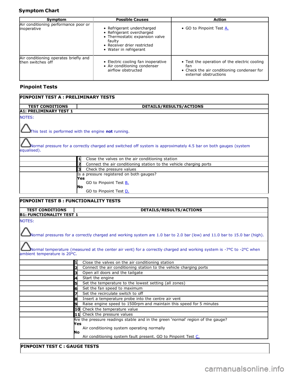
Symptom Chart
Symptom Possible Causes Action Air conditioning performance poor or
inoperative
Refrigerant undercharged
Refrigerant overcharged
Thermostatic expansion valve
faulty
Receiver drier restricted
Water in refrigerant
GO to Pinpoint Test A. Air conditioning operates briefly and
then switches off
Electric cooling fan inoperative
Air conditioning condenser
airflow obstructed
Test the operation of the electric cooling
fan
Check the air conditioning condenser for
external obstructions Pinpoint Tests
PINPOINT TEST A : PRELIMINARY TESTS TEST CONDITIONS DETAILS/RESULTS/ACTIONS A1: PRELIMINARY TEST 1 NOTES:
This test is performed with the engine not running.
Normal pressure for a correctly charged and switched off system is approximately 4.5 bar on both gauges (system
equalised). 1 Close the valves on the air conditioning station 2 Connect the air conditioning station to the vehicle charging ports 3 Check the pressure values Is a pressure registered on both gauges? Yes
GO to Pinpoint Test B. No
GO to Pinpoint Test D.
PINPOINT TEST B : FUNCTIONALITY TESTS TEST CONDITIONS DETAILS/RESULTS/ACTIONS B1: FUNCTIONALITY TEST 1 NOTES:
Normal pressures for a correctly charged and working system are 1.0 bar to 2.0 bar (low) and 11.0 bar to 15.0 bar (high).
Normal temperature (measured at the center air vent) for a correctly charged and working system is -7°C to -2°C when
ambient temperature is 20°C. 1 Close the valves on the air conditioning station 2 Connect the air conditioning station to the vehicle charging ports 3 Open all doors and the tailgate 4 Start the engine 5 Set the temperature to the lowest setting (all zones) 6 Set the fan speed to maximum 7 Set the recirculate switch to off 8 Insert a temperature probe into the centre air vent 9 Raise engine speed to 1500rpm and maintain this speed for 5 minutes 10 Check the temperature value 11 Check the pressure values Are the pressure readings stable and in the green 'normal' region of the gauge? Yes
Air conditioning system operating normally No
Air conditioning system fault present. GO to Pinpoint Test C.
PINPOINT TEST C : GAUGE TESTS
Page 1667 of 3039
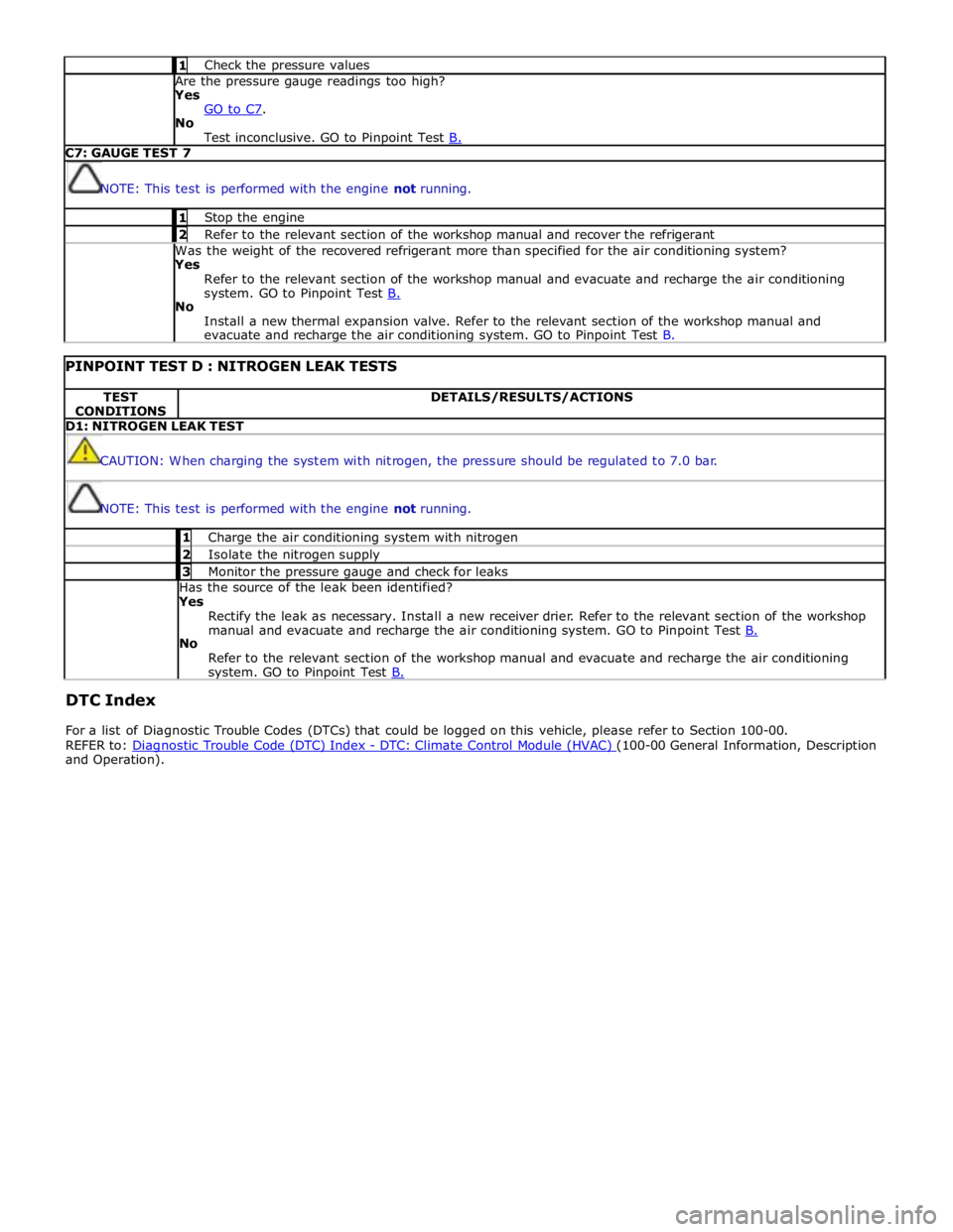
1 Check the pressure values Are the pressure gauge readings too high? Yes
GO to C7. No
Test inconclusive. GO to Pinpoint Test B. C7: GAUGE TEST 7
NOTE: This test is performed with the engine not running. 1 Stop the engine 2 Refer to the relevant section of the workshop manual and recover the refrigerant Was the weight of the recovered refrigerant more than specified for the air conditioning system? Yes
Refer to the relevant section of the workshop manual and evacuate and recharge the air conditioning
system. GO to Pinpoint Test B. No
Install a new thermal expansion valve. Refer to the relevant section of the workshop manual and
evacuate and recharge the air conditioning system. GO to Pinpoint Test B.
PINPOINT TEST D : NITROGEN LEAK TESTS TEST
CONDITIONS DETAILS/RESULTS/ACTIONS D1: NITROGEN LEAK TEST
CAUTION: When charging the system with nitrogen, the pressure should be regulated to 7.0 bar.
NOTE: This test is performed with the engine not running. 1 Charge the air conditioning system with nitrogen 2 Isolate the nitrogen supply 3 Monitor the pressure gauge and check for leaks Has the source of the leak been identified?
Yes
Rectify the leak as necessary. Install a new receiver drier. Refer to the relevant section of the workshop
manual and evacuate and recharge the air conditioning system. GO to Pinpoint Test B. No
Refer to the relevant section of the workshop manual and evacuate and recharge the air conditioning system. GO to Pinpoint Test B.
DTC Index
For a list of Diagnostic Trouble Codes (DTCs) that could be logged on this vehicle, please refer to Section 100-00.
REFER to: Diagnostic Trouble Code (DTC) Index - DTC: Climate Control Module (HVAC) (100-00 General Information, Description and Operation).
Page 1668 of 3039
Published: 11-May-2011
Climate Control System - General Information - Air Conditioning (A/C) System
Recovery, Evacuation and Charging
General Procedures
1. WARNING: Servicing must be carried out by personnel familliar with both
vehicle system and the charging and testing equipment. All operations
must be carried out in a well ventilated area away from open flame and
heat sources.
NOTE: The receiver drier need only be changed under the following
circumstances: There is dirt in the refrigerant circuit ( eg. compressor
seizure ), the system is leaking and refrigerant has been lost to
atmosphere, or the refrigerant circuit has been open more than 24 hours,
due to repair.
Refrigerant recovery.
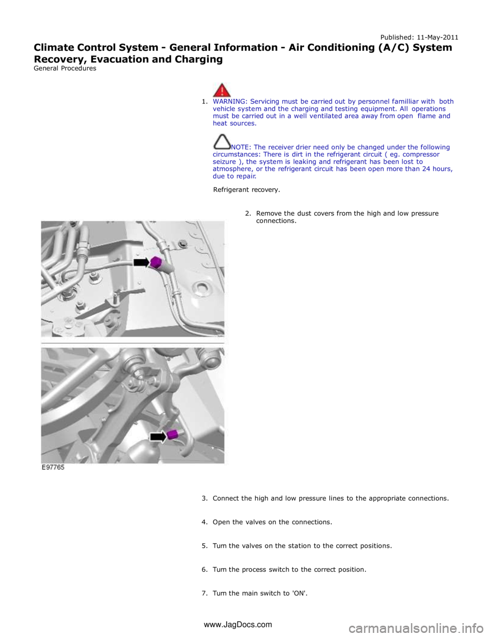
2. Remove the dust covers from the high and low pressure
connections.
3. Connect the high and low pressure lines to the appropriate connections.
4. Open the valves on the connections.
5. Turn the valves on the station to the correct positions.
6. Turn the process switch to the correct position.
7. Turn the main switch to 'ON'. www.JagDocs.com
Page 1669 of 3039
8. WARNING: Refrigerant must always be recycled before re-use to ensure
that the purity of the refrigerantis high enough for safe use in the air
conditioning system. Recycling should always be carried out with
equipment which is design certified by Underwriter Laboratory Inc. for
compliance with SEA J1991. Other equipment may not recycle refrigerant
to the required level of purity. R143a Refrigerant Recover Recycling
Recharging station must not be used with any other type of
refrigerant.Refrigerant R134a from domestic and comercial sources must
not be used in motor vehicles air conditioning systems.
Allow the system to recover the refrigerant from the system.
9. Close the valves on the refrigerant station.
10. Turn the main switch 'OFF'.
11. Close the valves on the connections.
12. Disconnect the high and low pressure connections.
13. Install the dust covers to the connectors.
14. Open the tap at the rear of the station to drain the refrigerant oil.
15. Measure and record the quantity of refrigerant oil recovered from the
system.
16. Close the tap at the rear of the station.
17. Evacuation.
18. Remove the dust covers from the high and low pressure connections.
19. Connect the high and low pressure lines to the appropriate connections.
20. Open the valves on the connections.
21. Turn the valves on the station to the correct positions.
22. Turn the process switch to the correct position.
23. Turn the main switch to 'ON'.
24. Allow the station to evacuate the A/C system.
25. CAUTION: The system must be evacuated immediatley before
recharging commences. Delay between evacuation and recharging is not
permitted
Recharging
26. Close the valves on the refrigerant station.
Page 1671 of 3039
Published: 11-May-2011
Climate Control System - General Information - Air Conditioning (A/C) System
Flushing
General Procedures
1. WARNINGS:
Use extreme care and observe all safety precautions related to the
use of refrigerants. Due to refrigerant hazards, always wear safety
goggles and non-penetrable gloves when working on or flushing air
conditioning (A/C) systems. Failure to follow this instruction may result
in personal injury.
When flushing the A/C system, refer to the manufacturers
equipment instructions for additional information. Failure to do so may
result in system damage or personal injury.
The A/C refrigerant analyzer must be used before the recovery of
any vehicle's A/C refrigerant. Failure to do so puts shop bulk refrigerant
at risk of contamination. If the vehicle A/C refrigerant is contaminated,
refer the customer to return to the repair facility that performed the last
A/C repair. If the customer wishes to pay the additional cost, use the
A/C recovery equipment that is designated for recovering contaminated
A/C refrigerant. All contaminated A/C refrigerant must be disposed of as
hazardous waste. For additional information, refer to the manufacturers
equipment instructions. Failure to follow this instruction may result in
personal injury.
Prior to using the A/C flushing equipment for the first time, follow
the operating instructions. Failure to follow this instruction may result in
personal injury.
CAUTION: Prior to flushing, remove and discard the desiccant sack.
Depending on the equipment used, other A/C components may have to
be removed prior to flushing. For additional information, refer to the
manufacturers equipment instructions before flushing the A/C system.
Recover the refrigerant.
For additional information, refer to Air conditioning (A/C) System Recovery, Evacuation and Charging in this section.
2. Remove the desiccant sack.
For additional information, refer to Section 412-03 Air Conditioning.
3. Flush the system. For additional information, refer to the manufacturers
equipment instructions.
4. Install new refrigerant lines if blocked with debris.
5. Install a new desiccant sack.
For additional information, refer to Section 412-03 Air Conditioning.
6. Add the required amount of oil to the A/C system depending on the
repair procedure.
For additional information, refer to Refrigerant Oil Adding in this section.
7. Evacuate and charge the A/C system.
For additional information, refer to Air conditioning (A/C) System Recovery, Evacuation and Charging in this section.
8. Carry out fluorescent dye leak detection test.