2010 JAGUAR XFR lock
[x] Cancel search: lockPage 2348 of 3039

DTC Description Possible Causes Action tests associated with this DTC using the
manufacturer approved diagnostic system B1223-13
Right Seat Cushion Temperature Sensor -
Circuit open
Connectors disconnected or
connector pin damage
Seat cushion temperature
sensor right circuit - Open
circuit
Front seat climate control
module failure
Check for any disconnected connectors or damaged
connector pins
Carry out on demand self test using manufacturer
approved diagnostic system to confirm the fault is
present
Refer to the electrical circuit diagrams and check
the front seat climate control module - Circuit
reference RH_CUSHION_SENSOR, Circuit reference
RH_CUSHION_SENSOR_RTN - For open circuit.
Repair circuit as required, clear DTC and retest
Carry out on demand self test using manufacturer
approved diagnostic system to confirm
rectification. Alternatively, carry out any pinpoint
tests associated with this DTC using the
manufacturer approved diagnostic system B1224-13
Left Thermal Electric
Device Control - Circuit
open
Connectors disconnected or
connector pin damage
Seat backrest thermal
electric device left circuit -
Open circuit
Seat cushion thermal
electric device left circuit -
Open circuit
Front seat climate control
module failure
Check for any disconnected connectors or damaged
connector pins
Carry out on demand self test using manufacturer
approved diagnostic system to confirm the fault is
present
Refer to the electrical circuit diagrams and check
the front seat climate control module - Circuit
reference LH_SEAT_BACK_TED+, Circuit reference
LH_SEAT_BACK_TED- - For short circuit to ground.
Repair circuit as required, clear DTC and retest
Refer to the electrical circuit diagrams and check
the front seat climate control module - Circuit
reference LH_CUSHION_TED+, Circuit reference
LH_CUSHION_TED- - For short circuit to ground.
Repair circuit as required, clear DTC and retest
Carry out on demand self test using manufacturer
approved diagnostic system to confirm
rectification. Alternatively, carry out any pinpoint
tests associated with this DTC using the
manufacturer approved diagnostic system B1224-19
Left Thermal Electric
Device Control - Circuit
current above threshold
Seat backrest thermal
electric device left circuit -
Short circuit to ground
Seat cushion thermal
electric device left circuit -
Short circuit to ground
Front seat climate control
module failure
Carry out on demand self test using manufacturer
approved diagnostic system to confirm the fault is
present
Refer to the electrical circuit diagrams and check
the front seat climate control module - Circuit
reference LH_SEAT_BACK_TED+, Circuit reference
LH_SEAT_BACK_TED- - For short circuit to ground.
Repair circuit as required, clear DTC and retest
Refer to the electrical circuit diagrams and check
the front seat climate control module - Circuit
reference LH_CUSHION_TED+, Circuit reference
LH_CUSHION_TED- - For short circuit to ground.
Repair circuit as required, clear DTC and retest
Carry out on demand self test using manufacturer
approved diagnostic system to confirm
rectification. Alternatively, carry out any pinpoint
tests associated with this DTC using the
manufacturer approved diagnostic system B1224-4B
Left Thermal Electric
Device Control - Over
temperature
Restriction in thermal
electric device air path
Seat backrest thermal
electric device left circuit -
Short circuit to ground
Seat cushion thermal
electric device left circuit -
Short circuit to ground
Front seat climate control
module failure
Check for blockage or restriction in thermal electric
device air path
Carry out on demand self test using manufacturer
approved diagnostic system to confirm the fault is
present
Refer to the electrical circuit diagrams and check
the front seat climate control module - Circuit
reference LH_SEAT_BACK_TED+, Circuit reference
LH_SEAT_BACK_TED- - For short circuit to ground.
Repair circuit as required, clear DTC and retest
Refer to the electrical circuit diagrams and check
the front seat climate control module - Circuit
reference LH_CUSHION_TED+, Circuit reference
LH_CUSHION_TED- - For short circuit to ground.
Repair circuit as required, clear DTC and retest
Carry out on demand self test using manufacturer
Page 2351 of 3039

DTC Description Possible Causes Action tests associated with this DTC using the
manufacturer approved diagnostic system B122E-98
Right Seat Cushion -
Component or system
over temperature
Blocked or restricted
thermal electric device fan
exhaust vent
Restricted thermal electric
device fan movement
Check for blockage or restriction in thermal electric
device fan exhaust vent
Check for restricted thermal electric device fan
movement
Carry out on demand self test using manufacturer
approved diagnostic system to confirm
rectification. Alternatively, carry out any pinpoint
tests associated with this DTC using the
manufacturer approved diagnostic system B122F-98
Right Seat Back -
Component or system
over temperature
Blocked or restricted
thermal electric device fan
exhaust vent
Restricted thermal electric
device fan movement
Check for blockage or restriction in thermal electric
device fan exhaust vent
Check for restricted thermal electric device fan
movement
Carry out on demand self test using manufacturer
approved diagnostic system to confirm
rectification. Alternatively, carry out any pinpoint
tests associated with this DTC using the
manufacturer approved diagnostic system B1230-98
Left Seat Back -
Component or system
over temperature
Blocked or restricted
thermal electric device fan
exhaust vent
Restricted thermal electric
device fan movement
Check for blockage or restriction in thermal electric
device fan exhaust vent
Check for restricted thermal electric device fan
movement
Carry out on demand self test using manufacturer
approved diagnostic system to confirm
rectification. Alternatively, carry out any pinpoint
tests associated with this DTC using the
manufacturer approved diagnostic system B1231-7A
Right Seat - Fluid leak
or seal failure
Seat backrest assembly -
Air path leaking
Seat cushion assembly -
Air path leaking
Seat assembly damaged
Check for blockage or restriction in seat
backrest/seat cushion thermal electric device fan
ducts
Check seat backrest/seat cushion thermal electric
device fan exhaust vent is clear
Carry out on demand self test using manufacturer
approved diagnostic system to confirm
rectification. Alternatively, carry out any pinpoint
tests associated with this DTC using the
manufacturer approved diagnostic system B1232-7A
Left Seat - Fluid leak or
seal failure
Seat backrest assembly -
Air path leaking
Seat cushion assembly -
Air path leaking
Seat assembly damaged
Check for blockage or restriction in seat
backrest/seat cushion thermal electric device fan
ducts
Check seat backrest/seat cushion thermal electric
device fan exhaust vent is clear
Carry out on demand self test using manufacturer
approved diagnostic system to confirm
rectification. Alternatively, carry out any pinpoint
tests associated with this DTC using the
manufacturer approved diagnostic system B1235-13
Left Seat Cushion Temperature Sensor -
Circuit open
Connectors disconnected or
connector pin damage
Seat cushion temperature
sensor left circuit - Open
circuit
Front seat climate control
module failure
Check for any disconnected connectors or damaged
connector pins
Carry out on demand self test using manufacturer
approved diagnostic system to confirm the fault is
present
Refer to the electrical circuit diagrams and check
the front seat climate control module - Circuit
reference LH_CUSHION_SENSOR, Circuit reference
LH_CUSHION_SENSOR_RTN - For open circuit.
Repair circuit as required, clear DTC and retest
Carry out on demand self test using manufacturer
approved diagnostic system to confirm
rectification. Alternatively, carry out any pinpoint
tests associated with this DTC using the
manufacturer approved diagnostic system
Page 2415 of 3039

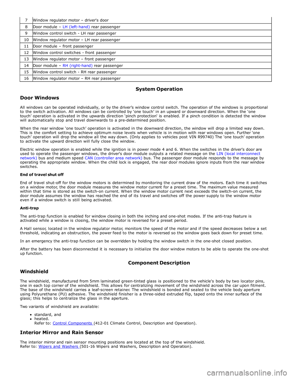
7 Window regulator motor – driver's door 8 Door module – LH (left-hand) rear passenger 9 Window control switch - LH rear passenger 10 Window regulator motor – LH rear passenger 11 Door module – front passenger 12 Window control switches - front passenger 13 Window regulator motor – front passenger 14 Door module – RH (right-hand) rear passenger 15 Window control switch - RH rear passenger 16 Window regulator motor – RH rear passenger
Door Windows System Operation
All windows can be operated individually, or by the driver’s window control switch. The operation of the windows is proportional
to the switch activation. All windows can be controlled by ‘one touch’ in an upward or downward direction. When the ‘one
touch’ operation is activated in the upwards direction ‘pinch protection‘ is enabled. If a pinch condition is detected the window
will automatically stop and travel downwards to a pre-determined position.
When the rear window ‘one touch’ operation is activated in the downward direction, the window will drop a limited way down.
This is the comfort setting to achieve optimum noise levels when vehicle is in motion with rear windows open. Further ‘one
touch’ operation will drop the window all the way down. (Only applies to vehicles post VIN R99740) The ‘one touch’ operation
to activate the upward direction will fully close the window.
Electric window operation is enabled while the ignition is in power mode 4 and 6. When the switches in the driver's door are
used to operate the passenger windows, the driver's door module outputs a related message on the LIN (local interconnect
network) bus and medium speed CAN (controller area network) bus. The passenger door module responds to the message by
operating the appropriate window. When the child lock is engaged, the rear door modules ignore inputs from the rear window
switches.
End of travel shut off
End of travel shut-off for the window motors is determined by monitoring the current draw of the motors. Each time it switches
on a window motor, the door module measures the window motor current for a preset time. The maximum value measured
within that time is stored as the switch-on current. When the window motor current next exceeds the switch-on current, the
door module assumes the window has reached the end of its travel and switches off the power supply to the window motor
even if a window switch is still being activated.
Anti-trap
The anti-trap function is enabled for window closing in both the inching and one-shot modes. If the anti-trap feature is
activated while a window is closing, the window motor is reversed for a preset period.
A Hall sensor, located in the window regulator motor, monitors the speed of the motor and if the speed decreases below a set
threshold, indicating an obstruction, the power feed to the motor is reversed so the window goes back down for preset time.
In an emergency the anti-trap function can be overridden by holding the window switch in the one-shot closed position.
After the battery has been disconnected it is necessary to initialize the door window motors to be able to operate the one-shot
up function.
Windshield Component Description
The windshield, manufactured from 5mm laminated green-tinted glass is positioned to the vehicle's body by two locator pins,
one in each top corner of the windshield. This allows for centralizing movement of the windshield across the car upon fitment.
The base of the windshield carries a leaf-screen retainer. The windshield is bonded and sealed to the vehicle body aperture
using Polyurethane (PU) adhesive. The windshield finisher is a three-sided extruded flip, taped onto the inner surface of the
glass; this helps to centralize the glass in the aperture.
Two variants of windshield are available:
standard, and
heated.
Refer to: Control Components (412-01 Climate Control, Description and Operation).
Interior Mirror and Rain Sensor
The interior mirror and rain sensor mounting positions are located at the top of the windshield.
Refer to: Wipers and Washers (501-16 Wipers and Washers, Description and Operation).
Page 2418 of 3039

Correctly install the door window seal. Test the system for correct operation A3: DOOR WINDOW - SECURITY
NOTE: To check the door window is secure 1 Check if the door window is installed correctly and secured to the door window regulator Is the door window correctly installed and secure?
Yes
GO to A4. No
Adjust the door window referring to the door window installation process REFER to: (501-11 Glass,
Frames and Mechanisms)
Front Door Window Glass (Removal and Installation), Rear Door Window Glass (Removal and Installation). Test the system for correct operation A4: DOOR WINDOW - RESET PROCEDURE 1 Disconnect vehicle battery, wait for a minimum of 2 minutes, then reconnect the battery 2 For vehicles pre-VIN S08680, the latest version of the diagnostic software must be loaded. SDD must be loaded with SDD DVD126_V6.03 and Calibration File 77 (or later) 3 For vehicles pre-VIN R54858, replace the front door window regulator motor, REFER to: Front Door Window Regulator and Motor (501-11 Glass, Frames and Mechanisms, Removal and Installation). 4 With the vehicle engine running, initialize the door window regulator motors, REFER to: Door Window Motor Initialization (501-11 Glass, Frames and Mechanisms, General Procedures). 5 Cycle the window 20 times, using the ‘one–touch’ function to open and close the window 6 NOTE: The door window regulator motor may thermally cut out after too many operations, if this occurs wait 30 seconds before continuing Is door window closing correctly and the One-touch function operational?
Yes
No further action requires
No
Replace the front door window regulator motor
REFER to: Door Window Regulator Motor (501-11 Glass, Frames and Mechanisms, Removal and Installation).
, or rear door window regulator motor
REFER to: Rear Door Window Regulator and Motor (501-11 Glass, Frames and Mechanisms, Removal and Installation).
Test the system for correct operation Manual Sunblind Initialization Routine
Where a sunblind module has been replaced, there is an initialization routine available on the diagnostic tool. This requires a
new module to be initially installed in the fully down position and running of the "Initialize Specified Function/Feature"
diagnostic routine on the manufacturer approved diagnostic tool. Alternatively, the sunblind may be initialized manually by
following the procedures described below:
1. Raise the sunblind to top (fully retracted) position
2. Press and hold the door window 'down' switch for 15 seconds (the sunblind will go down and will then be in
initialization mode)
3. Release door window drop switch and press door window 'down' switch again to drive blind fully into lower block
4. Activate window switch 'up' until the sunblind reaches the top (fully retracted) position and release switch
5. The sunblind is now initialized and should have 'one-touch' functionality
DTC Index
For a complete list of all diagnostic trouble codes that could be logged on this vehicle, please refer to Section 100-00.
REFER to: Driver Door Module (DDM) (419-10 Multifunction Electronic Modules, Diagnosis and Testing).
Page 2451 of 3039

a power supply to operate the glovebox latch to unlock the glovebox.
The glove box opening is inhibited by the CJB if the anti-theft alarm system is armed and if valet mode is selected using the Touch Screen Display (TSD). The CJB detects the voltage signal from the switch but will not operate the glovebox latch if other condition exists.
GLOVEBOX SWITCH DESCRIPTION Component Description
The conventional glove box switch is located behind the instrument panel veneer. The round button of the switch is visible
through an aperture in the veneer.
Two screws hold the switch in position behind the veneer. The veneer panel has two bosses which the screws are threaded
into.
Page 2486 of 3039

Front and rear door latch retaining screw 7 - 62 Front and Rear exterior door handle / Door lock captive retaining screw 4 - 36 Front and Rear Exterior Door handle seperate retaining screw 3 - 28 Front and Rear Door striker retaining screw 25 18 - Interior Door handle retaining Screw 1.3 - 11.5 Hood latch Reataining screw 10 8 - Hood Striker Retaining screw 22 17 - Trunk Latch Retaining screw 20 15 - Trunk Striker Retaining screw 22 17 - Trunk Lock Retaining screw 3 - 28
Page 2488 of 3039

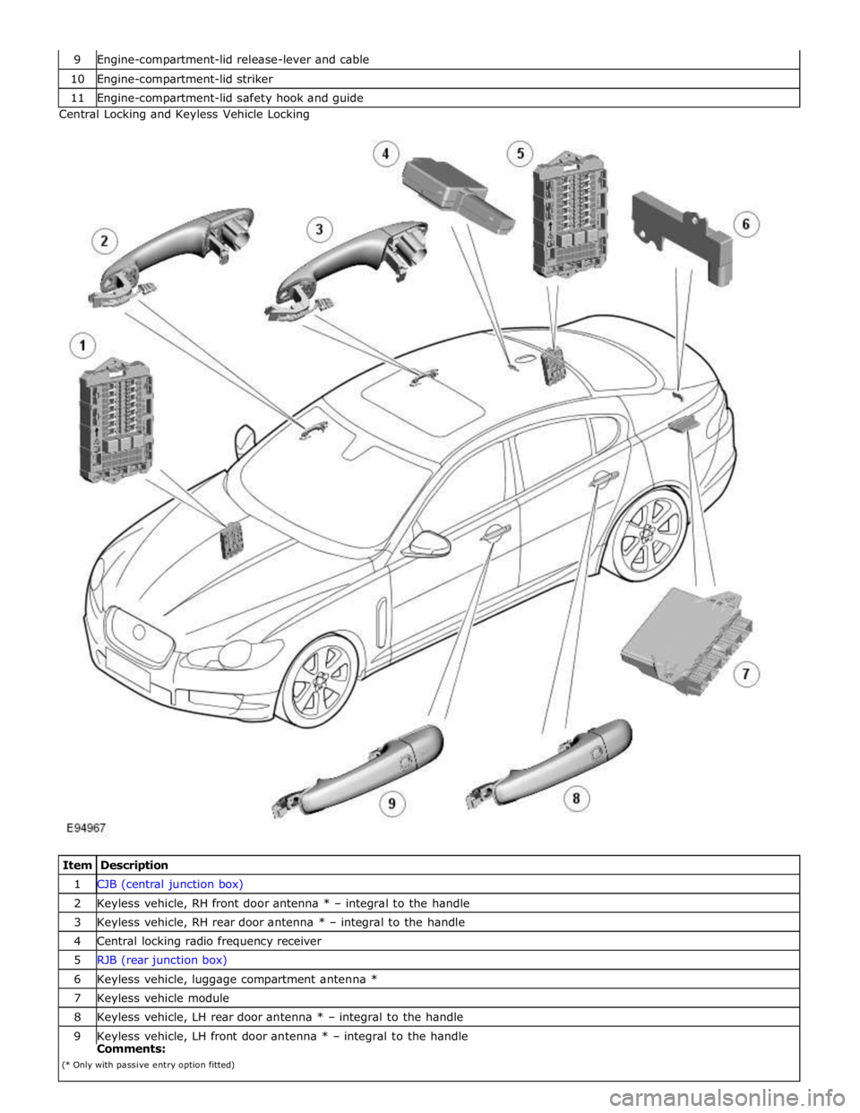
10 Engine-compartment-lid striker 11 Engine-compartment-lid safety hook and guide Central Locking and Keyless Vehicle Locking
Item Description 1 CJB (central junction box) 2 Keyless vehicle, RH front door antenna * – integral to the handle 3 Keyless vehicle, RH rear door antenna * – integral to the handle 4 Central locking radio frequency receiver 5 RJB (rear junction box) 6 Keyless vehicle, luggage compartment antenna * 7 Keyless vehicle module 8 Keyless vehicle, LH rear door antenna * – integral to the handle 9 Keyless vehicle, LH front door antenna * – integral to the handle Comments:
(* Only with passive entry option fitted)
Page 2491 of 3039

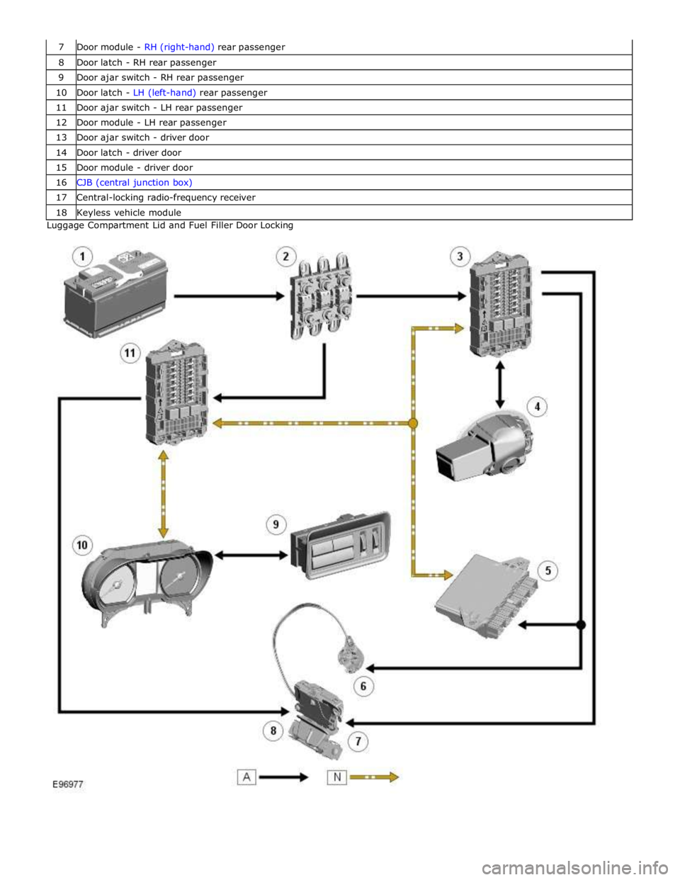
8 Door latch - RH rear passenger 9 Door ajar switch - RH rear passenger 10 Door latch - LH (left-hand) rear passenger 11 Door ajar switch - LH rear passenger 12 Door module - LH rear passenger 13 Door ajar switch - driver door 14 Door latch - driver door 15 Door module - driver door 16 CJB (central junction box) 17 Central-locking radio-frequency receiver 18 Keyless vehicle module Luggage Compartment Lid and Fuel Filler Door Locking