2010 JAGUAR XFR lock
[x] Cancel search: lockPage 2212 of 3039
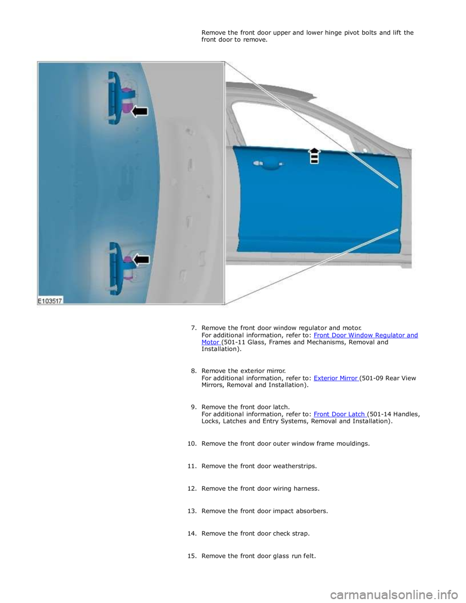
Motor (501-11 Glass, Frames and Mechanisms, Removal and Installation).
8. Remove the exterior mirror.
For additional information, refer to: Exterior Mirror (501-09 Rear View Mirrors, Removal and Installation).
9. Remove the front door latch.
For additional information, refer to: Front Door Latch (501-14 Handles, Locks, Latches and Entry Systems, Removal and Installation).
10. Remove the front door outer window frame mouldings.
11. Remove the front door weatherstrips.
12. Remove the front door wiring harness.
13. Remove the front door impact absorbers.
14. Remove the front door check strap.
15. Remove the front door glass run felt.
Page 2219 of 3039
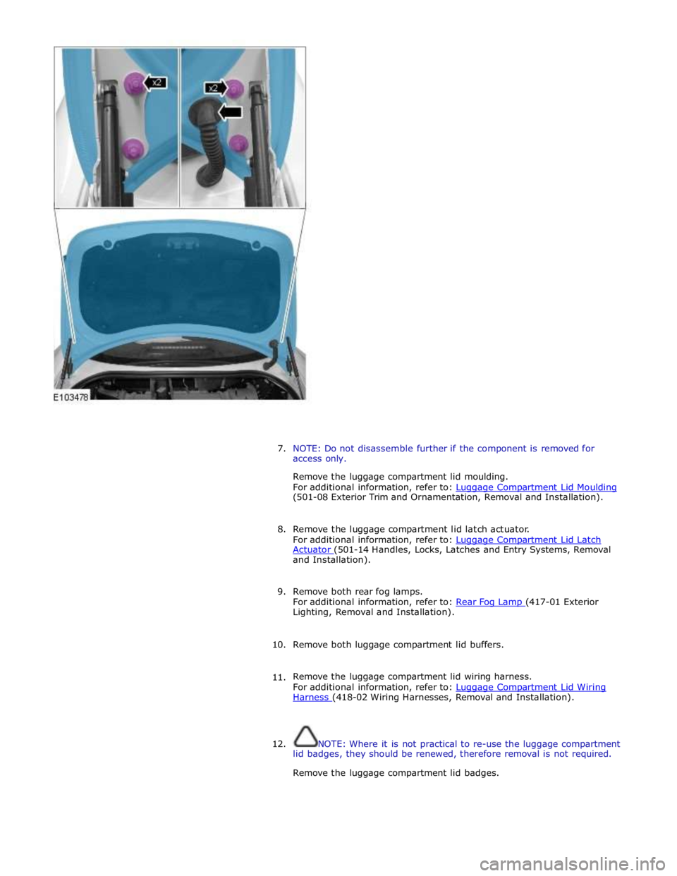
7. NOTE: Do not disassemble further if the component is removed for
access only.
Remove the luggage compartment lid moulding.
For additional information, refer to: Luggage Compartment Lid Moulding (501-08 Exterior Trim and Ornamentation, Removal and Installation).
8. Remove the luggage compartment lid latch actuator.
For additional information, refer to: Luggage Compartment Lid Latch Actuator (501-14 Handles, Locks, Latches and Entry Systems, Removal and Installation).
9. Remove both rear fog lamps.
For additional information, refer to: Rear Fog Lamp (417-01 Exterior Lighting, Removal and Installation).
10. Remove both luggage compartment lid buffers.
11. Remove the luggage compartment lid wiring harness.
For additional information, refer to: Luggage Compartment Lid Wiring Harness (418-02 Wiring Harnesses, Removal and Installation).
12. NOTE: Where it is not practical to re-use the luggage compartment
lid badges, they should be renewed, therefore removal is not required.
Remove the luggage compartment lid badges.
Page 2222 of 3039
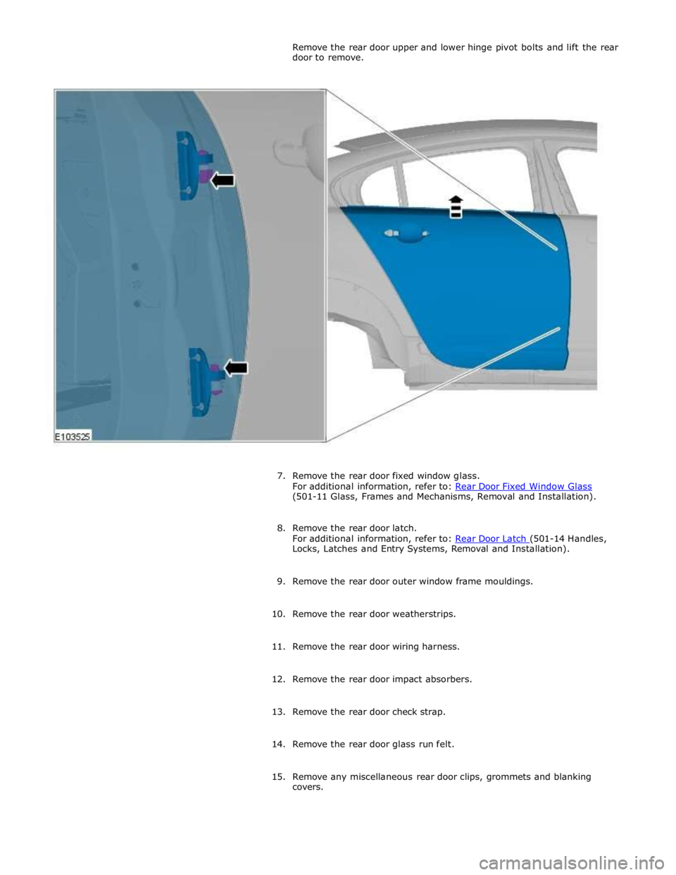
(501-11 Glass, Frames and Mechanisms, Removal and Installation).
8. Remove the rear door latch.
For additional information, refer to: Rear Door Latch (501-14 Handles, Locks, Latches and Entry Systems, Removal and Installation).
9. Remove the rear door outer window frame mouldings.
10. Remove the rear door weatherstrips.
11. Remove the rear door wiring harness.
12. Remove the rear door impact absorbers.
13. Remove the rear door check strap.
14. Remove the rear door glass run felt.
15. Remove any miscellaneous rear door clips, grommets and blanking
covers.
Page 2294 of 3039
8 LH door module 9 Exterior mirror control switches
System Operation
The rear view mirrors comprise an interior mirror mounted to the windshield, and an exterior mirror mounted on each front door
cheater. The types of mirrors and associated operating functions installed depend on the specification and trim level of the
vehicle.
Interior Mirrors
The interior rear view mirror is provided as a manual dimming or an electrically operated automatic dimming type.
The manual dimming mirror comprises a prismatic glass housed within a surrounding case that is attached with a ball joint
connector to the mirror stem. Manual dimming of the mirror is achieved using the lever mounted on the underside of the mirror
body. Operating the lever will tilt the mirror head from the 'day' position to the 'night' position.
The automatic dimming mirror comprises an electro-chromatic glass housed within a surrounding case that is attached with a
ball joint connector to the mirror stem. The mirror stem incorporates an 8-pin electrical connector that is connected to the roof
panel wiring harness. The wiring harness provides hardwired and a LIN connection to the CJB.
Light sensors are mounted on the front and rear of the mirror surround case. The sensors control the automatic dimming
feature to reduce glare from the headlights of following vehicles.
The automatic dimming function is permanently active when the ignition is in power mode 4 (Accessory) and power mode 6
(Ignition). The forward facing light sensor monitors the ambient light level at the front of the vehicle; the rearward facing light
sensor monitors the light level coming from the rear of the vehicle. When light from the rear of the vehicle exceeds the
ambient light level from the front of the vehicle, the automatic dimming circuit darkens the interior mirror surface.
Automatic dimming is inhibited when reverse gear is selected to provide the driver with maximum vision. On vehicles with
automatic transmission, the reverse gear signal is provided by the TCM (transmission control module) via the high speed CAN bus to the CJB. The CJB then provides a power feed to the mirror. On vehicles with manual transmission, the reverse gear signal is provided by a transmission switch that is hardwired to the CJB.
Exterior Mirrors
Electrically operated and heated exterior mirrors are installed as standard. Depending on the specification and trim level of the
vehicle, the following options are available:
Power fold (switch pack operated feature) and auto fold (remote handset operated feature)
Memory recall
Reverse gear mirror dip
Mirror heating
Exterior mirror lamps.
The power fold/auto fold feature is available only when power fold mirrors are installed to the vehicle.
The mirrors can be configured to automatically fold when the vehicle is locked and unfold when unlocked. This feature can be
enabled or disabled via the Vehicle settings area of the touch screen:
Select 'Settings' from the touch screen Home menu.
Select ' Security/Vehicle'
Select 'Windows/Mirrors'
Select Power Fold 'On' or 'Off' as appropriate.
The pasenger side mirror can be configured to automatically dip when reverse gear is selected. This feature can be enabled or
disabled via the Vehicle settings area of the touch screen:
Select 'Settings' from the touch screen Home menu.
Select ' Security/Vehicle'
Select 'Windows/Mirrors'
Select Reverse dip 'On' or 'Off' as appropriate.
The LH door mirror incorporates an ambient air temperature sensor that is hardwired to the ECM (engine control module). The ECM is connected to the CJB and other control modules via the high speed CAN bus. The sensor provides information to the ECM that is then transmitted on the medium speed CAN bus for use by other control modules. On vehicles installed with a high-line instrument cluster, the CJB transmits the temperature signal to the instrument cluster that provides a display of the ambient temperature to the driver.
The exterior mirror lamps are controlled by the interior lighting function.
The door mirrors are controlled using a switch pack located on the driver's door. The switch pack contains 2 non-latching mirror
select switches labeled 'L' and 'R' and a 4-way directional joystick. The switch pack is connected to the driver door control
module via the LIN bus. The driver and front passenger door control modules are connected via the medium speed CAN bus. A hardwired connection between each door control module and the corresponding door mirror, provides the supply and ground
paths for the mirror motors.
Each exterior door mirror incorporates 2 motors to control horizontal (left/right) and vertical (up/down) adjustments. www.JagDocs.com
Page 2295 of 3039
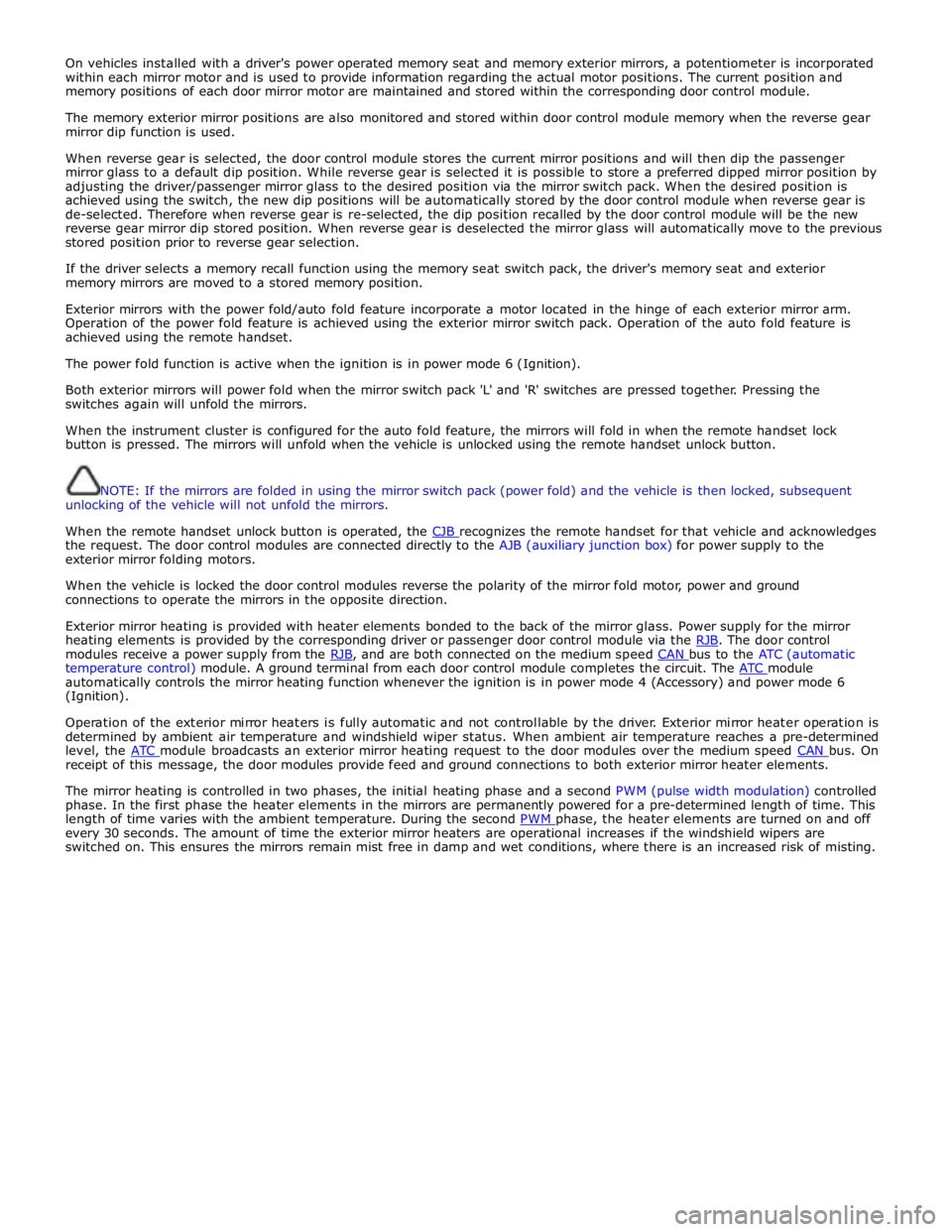
On vehicles installed with a driver's power operated memory seat and memory exterior mirrors, a potentiometer is incorporated
within each mirror motor and is used to provide information regarding the actual motor positions. The current position and
memory positions of each door mirror motor are maintained and stored within the corresponding door control module.
The memory exterior mirror positions are also monitored and stored within door control module memory when the reverse gear
mirror dip function is used.
When reverse gear is selected, the door control module stores the current mirror positions and will then dip the passenger
mirror glass to a default dip position. While reverse gear is selected it is possible to store a preferred dipped mirror position by
adjusting the driver/passenger mirror glass to the desired position via the mirror switch pack. When the desired position is
achieved using the switch, the new dip positions will be automatically stored by the door control module when reverse gear is
de-selected. Therefore when reverse gear is re-selected, the dip position recalled by the door control module will be the new
reverse gear mirror dip stored position. When reverse gear is deselected the mirror glass will automatically move to the previous
stored position prior to reverse gear selection.
If the driver selects a memory recall function using the memory seat switch pack, the driver's memory seat and exterior
memory mirrors are moved to a stored memory position.
Exterior mirrors with the power fold/auto fold feature incorporate a motor located in the hinge of each exterior mirror arm.
Operation of the power fold feature is achieved using the exterior mirror switch pack. Operation of the auto fold feature is
achieved using the remote handset.
The power fold function is active when the ignition is in power mode 6 (Ignition).
Both exterior mirrors will power fold when the mirror switch pack 'L' and 'R' switches are pressed together. Pressing the
switches again will unfold the mirrors.
When the instrument cluster is configured for the auto fold feature, the mirrors will fold in when the remote handset lock
button is pressed. The mirrors will unfold when the vehicle is unlocked using the remote handset unlock button.
NOTE: If the mirrors are folded in using the mirror switch pack (power fold) and the vehicle is then locked, subsequent
unlocking of the vehicle will not unfold the mirrors.
When the remote handset unlock button is operated, the CJB recognizes the remote handset for that vehicle and acknowledges the request. The door control modules are connected directly to the AJB (auxiliary junction box) for power supply to the
exterior mirror folding motors.
When the vehicle is locked the door control modules reverse the polarity of the mirror fold motor, power and ground
connections to operate the mirrors in the opposite direction.
Exterior mirror heating is provided with heater elements bonded to the back of the mirror glass. Power supply for the mirror
heating elements is provided by the corresponding driver or passenger door control module via the RJB. The door control modules receive a power supply from the RJB, and are both connected on the medium speed CAN bus to the ATC (automatic temperature control) module. A ground terminal from each door control module completes the circuit. The ATC module automatically controls the mirror heating function whenever the ignition is in power mode 4 (Accessory) and power mode 6
(Ignition).
Operation of the exterior mirror heaters is fully automatic and not controllable by the driver. Exterior mirror heater operation is
determined by ambient air temperature and windshield wiper status. When ambient air temperature reaches a pre-determined
level, the ATC module broadcasts an exterior mirror heating request to the door modules over the medium speed CAN bus. On receipt of this message, the door modules provide feed and ground connections to both exterior mirror heater elements.
The mirror heating is controlled in two phases, the initial heating phase and a second PWM (pulse width modulation) controlled
phase. In the first phase the heater elements in the mirrors are permanently powered for a pre-determined length of time. This
length of time varies with the ambient temperature. During the second PWM phase, the heater elements are turned on and off every 30 seconds. The amount of time the exterior mirror heaters are operational increases if the windshield wipers are
switched on. This ensures the mirrors remain mist free in damp and wet conditions, where there is an increased risk of misting.
Page 2344 of 3039
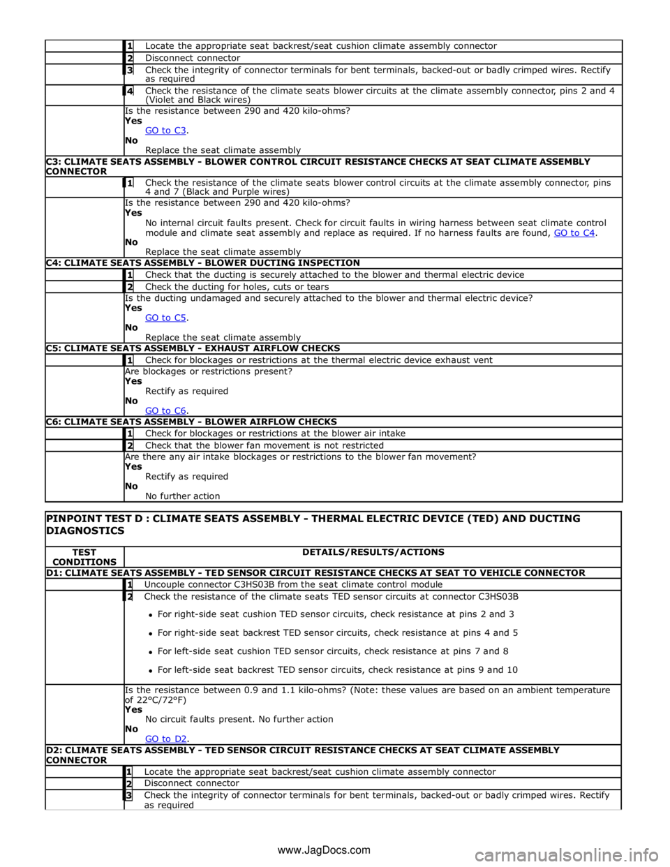
1 Locate the appropriate seat backrest/seat cushion climate assembly connector 2 Disconnect connector 3 Check the integrity of connector terminals for bent terminals, backed-out or badly crimped wires. Rectify as required 4 Check the resistance of the climate seats blower circuits at the climate assembly connector, pins 2 and 4 (Violet and Black wires) Is the resistance between 290 and 420 kilo-ohms?
Yes
GO to C3. No
Replace the seat climate assembly C3: CLIMATE SEATS ASSEMBLY - BLOWER CONTROL CIRCUIT RESISTANCE CHECKS AT SEAT CLIMATE ASSEMBLY
CONNECTOR 1 Check the resistance of the climate seats blower control circuits at the climate assembly connector, pins 4 and 7 (Black and Purple wires) Is the resistance between 290 and 420 kilo-ohms?
Yes
No internal circuit faults present. Check for circuit faults in wiring harness between seat climate control
module and climate seat assembly and replace as required. If no harness faults are found, GO to C4. No
Replace the seat climate assembly C4: CLIMATE SEATS ASSEMBLY - BLOWER DUCTING INSPECTION 1 Check that the ducting is securely attached to the blower and thermal electric device 2 Check the ducting for holes, cuts or tears Is the ducting undamaged and securely attached to the blower and thermal electric device?
Yes
GO to C5. No
Replace the seat climate assembly C5: CLIMATE SEATS ASSEMBLY - EXHAUST AIRFLOW CHECKS 1 Check for blockages or restrictions at the thermal electric device exhaust vent Are blockages or restrictions present?
Yes
Rectify as required
No
GO to C6. C6: CLIMATE SEATS ASSEMBLY - BLOWER AIRFLOW CHECKS 1 Check for blockages or restrictions at the blower air intake 2 Check that the blower fan movement is not restricted Are there any air intake blockages or restrictions to the blower fan movement?
Yes
Rectify as required
No
No further action
PINPOINT TEST D : CLIMATE SEATS ASSEMBLY - THERMAL ELECTRIC DEVICE (TED) AND DUCTING
DIAGNOSTICS TEST
CONDITIONS DETAILS/RESULTS/ACTIONS D1: CLIMATE SEATS ASSEMBLY - TED SENSOR CIRCUIT RESISTANCE CHECKS AT SEAT TO VEHICLE CONNECTOR 1 Uncouple connector C3HS03B from the seat climate control module 2 Check the resistance of the climate seats TED sensor circuits at connector C3HS03B For right-side seat cushion TED sensor circuits, check resistance at pins 2 and 3
For right-side seat backrest TED sensor circuits, check resistance at pins 4 and 5
For left-side seat cushion TED sensor circuits, check resistance at pins 7 and 8
For left-side seat backrest TED sensor circuits, check resistance at pins 9 and 10 Is the resistance between 0.9 and 1.1 kilo-ohms? (Note: these values are based on an ambient temperature
of 22°C/72°F)
Yes
No circuit faults present. No further action
No
GO to D2. D2: CLIMATE SEATS ASSEMBLY - TED SENSOR CIRCUIT RESISTANCE CHECKS AT SEAT CLIMATE ASSEMBLY
CONNECTOR 1 Locate the appropriate seat backrest/seat cushion climate assembly connector 2 Disconnect connector 3 Check the integrity of connector terminals for bent terminals, backed-out or badly crimped wires. Rectify as required www.JagDocs.com
Page 2345 of 3039
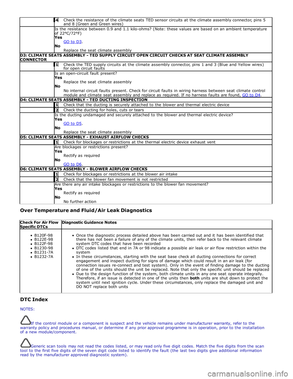
4 Check the resistance of the climate seats TED sensor circuits at the climate assembly connector, pins 5 and 8 (Green and Green wires) Is the resistance between 0.9 and 1.1 kilo-ohms? (Note: these values are based on an ambient temperature
of 22°C/72°F)
Yes
GO to D3. No
Replace the seat climate assembly D3: CLIMATE SEATS ASSEMBLY - TED SUPPLY CIRCUIT OPEN CIRCUIT CHECKS AT SEAT CLIMATE ASSEMBLY
CONNECTOR 1 Check the TED supply circuits at the climate assembly connector, pins 1 and 3 (Blue and Yellow wires) for open circuit faults Is an open-circuit fault present?
Yes
Replace the seat climate assembly
No
No internal circuit faults present. Check for circuit faults in wiring harness between seat climate control
module and climate seat assembly and replace as required. If no harness faults are found, GO to D4. D4: CLIMATE SEATS ASSEMBLY - TED DUCTING INSPECTION 1 Check that the ducting is securely attached to the blower and thermal electric device 2 Check the ducting for holes, cuts or tears Is the ducting undamaged and securely attached to the blower and thermal electric device?
Yes
GO to D5. No
Replace the seat climate assembly D5: CLIMATE SEATS ASSEMBLY - EXHAUST AIRFLOW CHECKS 1 Check for blockages or restrictions at the thermal electric device exhaust vent Are blockages or restrictions present?
Yes
Rectify as required
No
GO to D6. D6: CLIMATE SEATS ASSEMBLY - BLOWER AIRFLOW CHECKS 1 Check for blockages or restrictions at the blower air intake 2 Check that the blower fan movement is not restricted Are there any air intake blockages or restrictions to the blower fan movement?
Yes
Rectify as required
No
No further action Over Temperature and Fluid/Air Leak Diagnostics
Check For Air Flow Specific DTCs Diagnostic Guidance Notes
B120F-98
Once the diagnostic process detailed above has been carried out and it has been identified that B122E-98 there has not been a failure of any of the climate units, then refer back to the relevant climate B122F-98 system DTC codes that have been recorded B1230-98 DTC codes listed that end in 7A or 98 indicate a possible air leak or air flow restriction within the B1231-7A system B1232-7A In these circumstances, starting with the seat base check all ducting connections for correct engagement and inspect ducting for signs of damage which could result in an air leak (for connection issues re-connect and test system). Only in the event of finding damage to the ducting of one of the units should the unit be replaced. Note that only the specific unit should be replaced Due to the design function of the system, both climate units in any one seat operate integrally. Therefore, if an issue is detected in one of the units then both units are shut down to protect the system until next ignition cycle. Under these circumstances, only replace the damaged unit and DO NOT replace both units DTC Index
NOTES:
If the control module or a component is suspect and the vehicle remains under manufacturer warranty, refer to the
warranty policy and procedures manual, or determine if any prior approval programme is in operation, prior to the installation
of a new module/component.
Generic scan tools may not read the codes listed, or may read only five digit codes. Match the five digits from the scan
tool to the first five digits of the seven digit code listed to identify the fault (the last two digits give additional information
read by the manufacturer approved diagnostic system).
Page 2347 of 3039

DTC Description Possible Causes Action circuit as required, clear DTC and retest
Carry out on demand self test using manufacturer
approved diagnostic system to confirm
rectification. Alternatively, carry out any pinpoint
tests associated with this DTC using the
manufacturer approved diagnostic system B120E-13
Right Thermal Electric
Device Control - Circuit
open
Connectors disconnected or
connector pin damage
Seat backrest thermal
electric device right circuit
- Open circuit
Seat cushion thermal
electric device right circuit
- Open circuit
Front seat climate control
module failure
Check for any disconnected connectors or damaged
connector pins
Carry out on demand self test using manufacturer
approved diagnostic system to confirm the fault is
present
Refer to the electrical circuit diagrams and check
the front seat climate control module - Circuit
reference RH_SEAT_BACK_TED+, Circuit reference
RH_SEAT_BACK_TED- - For open circuit. Repair
circuit as required, clear DTC and retest
Refer to the electrical circuit diagrams and check
the front seat climate control module - Circuit
reference RH_CUSHION_TED+, Circuit reference
RH_CUSHION_TED- - For open circuit. Repair circuit
as required, clear DTC and retest
Carry out on demand self test using manufacturer
approved diagnostic system to confirm
rectification. Alternatively, carry out any pinpoint
tests associated with this DTC using the
manufacturer approved diagnostic system B120E-19
Right Thermal Electric
Device Control - Circuit
current above threshold
Seat backrest thermal
electric device right circuit
- Short circuit to ground
Seat cushion thermal
electric device right circuit
- Short circuit to ground
Front seat climate control
module failure
Carry out on demand self test using manufacturer
approved diagnostic system to confirm the fault is
present
Refer to the electrical circuit diagrams and check
the front seat climate control module - Circuit
reference RH_SEAT_BACK_TED+, Circuit reference
RH_SEAT_BACK_TED- - For short circuit to ground.
Repair circuit as required, clear DTC and retest
Refer to the electrical circuit diagrams and check
the front seat climate control module - Circuit
reference RH_CUSHION_TED+, Circuit reference
RH_CUSHION_TED- - For short circuit to ground.
Repair circuit as required, clear DTC and retest
Carry out on demand self test using manufacturer
approved diagnostic system to confirm
rectification. Alternatively, carry out any pinpoint
tests associated with this DTC using the
manufacturer approved diagnostic system B120E-4B
Right Thermal Electric
Device Control - Over
temperature
Restriction in thermal
electric device air path
Seat backrest thermal
electric device right circuit
- Short circuit to ground
Seat cushion thermal
electric device right circuit
- Short circuit to ground
Front seat climate control
module failure
Check for blockage or restriction in thermal electric
device air path
Carry out on demand self test using manufacturer
approved diagnostic system to confirm the fault is
present
Refer to the electrical circuit diagrams and check
the front seat climate control module - Circuit
reference RH_SEAT_BACK_TED+, Circuit reference
RH_SEAT_BACK_TED- - For short circuit to ground.
Repair circuit as required, clear DTC and retest
Refer to the electrical circuit diagrams and check
the front seat climate control module - Circuit
reference RH_CUSHION_TED+, Circuit reference
RH_CUSHION_TED- - For short circuit to ground.
Repair circuit as required, clear DTC and retest
Carry out on demand self test using manufacturer
approved diagnostic system to confirm
rectification. Alternatively, carry out any pinpoint
tests associated with this DTC using the
manufacturer approved diagnostic system B120F-98
Left Seat Cushion -
Component or system
over temperature
Blocked or restricted
thermal electric device fan
exhaust vent
Restricted thermal electric
device fan movement
Check for blockage or restriction in thermal electric
device fan exhaust vent
Check for restricted thermal electric device fan
movement
Carry out on demand self test using manufacturer
approved diagnostic system to confirm
rectification. Alternatively, carry out any pinpoint