2010 JAGUAR XFR turn signal
[x] Cancel search: turn signalPage 800 of 3039
path is completed and a signal voltage is returned to the instrument cluster via a resistor. The returned reference voltage is
detected by the instrument cluster and performs the requested trip function.
RIGHT HAND MULTIFUNCTION SWITCH
The instrument cluster outputs 4 separate reference voltages to the following switch functions:
Wash/wipe switch
Intermittent wipe switch
Master wiper switch
Flick wipe switch.
Wash/Wipe Switch
The reference voltage is supplied to one of two resistors connected in parallel. When the switch is not being operated the
current flows through one resistor and the returned signal voltage is monitored by the instrument cluster. When the wash/wipe
switch is operated, a connection is made and the current flows through the second resistor. The change in signal voltage is
detected by the instrument cluster which outputs a message on the medium speed CAN bus to the CJB to activate the wash/wipe function.
Intermittent Delay/Auto Wipe Switch
The reference voltage is supplied to the switch and can pass through up to 7 resistors, connected in series, for intermittent
delay selections and the auto wipe function.
When the rotary switch is in the auto position the reference voltage flows through 1 resistor. The returned signal voltage is
detected by the instrument cluster which determines auto wipe is selected. The instrument cluster outputs a message on the
medium speed CAN bus to the CJB to activate the auto wipe function.
With the rotary switch in one of the intermittent positions, the reference voltage is routed through up to 7 of the resistors
depending on the delay period selected. The returned signal voltage is detected by the instrument cluster which determines
selected delay period. The instrument cluster outputs a message on the medium speed CAN bus to the CJB to activate the selected intermittent wipe function.
NOTE: The delay period for the intermittent selections can vary according to vehicle speed.
Master Wiper Switch
The reference voltage supplied from the instrument cluster to the master wiper switch. The voltage can pass through up to 4
resistors connected in series.
When the switch is in the off position, the reference voltage passes through 4 resistors and the returned voltage is monitored
by the instrument cluster. The instrument cluster outputs a message on the medium speed CAN bus to the CJB that no wiper selections have been requested.
With the switch in the intermittent, slow wipe or fast wipe position, the reference voltage passes through 3, 2 or 1 resistors
respectively. The returned signal voltage is detected by the instrument cluster which determines selected delay period. The
instrument cluster outputs a message on the medium speed CAN bus to the CJB to activate the selected wipe function. Flick Wipe Switch
The reference voltage is supplied to one of two resistors connected in parallel. When the switch is not being operated the
current flows through one resistor and the returned signal voltage is monitored by the instrument cluster. When the flick wipe
switch is operated, a connection is made and the current flows through the second resistor. The change in signal voltage is
detected by the instrument cluster which outputs a message on the medium speed CAN bus to the CJB to activate the flick wipe function.
STEERING COLUMN ADJUSTMENT SWITCH
The instrument cluster supplies 2 reference voltages to the column adjustment switch.
The first reference voltage is supplied to the joystick switch. When the switch is moved to one of its 4 positions, the switch
contact is completed and the reference voltage is passed through one of 4 different resistors with different values. The
returned signal voltage is measured by the instrument cluster which determines the selected column adjust request. The
instrument cluster outputs a supply to the steering column adjustment motor and energizes the applicable clutch solenoid to
move the column to the desired position.
The second reference voltage is supplied to the auto/manual selection of the switch. When the switch is in the auto position,
the reference voltage passes directly through the switch contacts and is measured by the instrument cluster. The instrument
cluster outputs a message on the medium speed CAN bus to the driver seat module which responds with the recorded memory position setting. The instrument cluster then activates the column adjustment motor and clutch solenoids to move the column
to the memorized position. When the switch is in the manual position the reference circuit is broken. The instrument cluster
detects the broken circuit and allows manual operation of the column adjustment switch to move the column.
HEATED STEERING WHEEL
The heated steering wheel receives a battery power supply via the CJB. The heated steering wheel is controlled by the driver using a selection on the TSD. When the driver selects the heated steering wheel to be active, the request is passed from the
TSD on the MOST ring to the information and entertainment module. The information and entertainment module converts the
Page 801 of 3039

battery power supply to be passed via the slip ring assembly in the steering wheel to the heated steering wheel control
module. The steering wheel module supplies power to the steering wheel heater element and also monitors the temperature
via a NTC (negative temperature coefficient) temperature sensor incorporated into the heater element. The control module
varies the power supply to the element to maintain the steering wheel rim at the optimum temperature.
Component Description STEERING COLUMN MULTIFUNCTION SWITCHES
The steering column multifunction switches are situated on the steering column and consists of the wiper switch, the turn
signal indicator/lighting switch and the trip computer switch.
The steering column adjustment switch is located in the steering column lower shroud on the LH side. The switch is a 4 position 'joystick' which controls reach and rake adjustment.
Steering wheel mounted switches on the LH side of the driver's airbag, control the audio and telephone functions. Switches on the RH side of the driver's airbag, control the speed control functions. For additional information, refer to:
Audio System (415-01A Information and Entertainment System, Description and Operation), Speed Control (310-03A, Description and Operation),
Speed Control (310-03B, Description and Operation),
Speed Control (310-03C, Description and Operation).
Two transmission paddle switches are located at the rear of the steering wheel.
Refer to: External Controls (307-05, Description and Operation).
LH Multifunction Switch
Item Description 1 High beam 2 Lighting control rotary switch 3 RH turn signal indicator 4 Headlamp flash 5 LH turn signal indicator 6 Trip computer function button The LH multifunction switch controls the following windshield wiper functions:
Page 802 of 3039
Turn signal indicators
Side lamps
Headlamps
Auto lamps
High/low beam
Headlamp flash
Headlamp timer
Trip computer.
The switch is located in a slot in the clockspring and secured with 2 plastic clips.
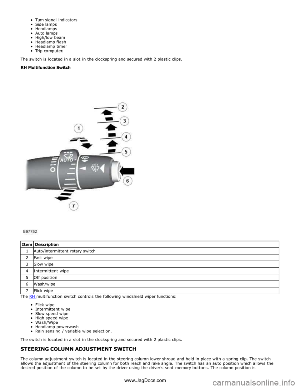
RH Multifunction Switch
The RH multifunction switch controls the following windshield wiper functions: Flick wipe
Intermittent wipe
Slow speed wipe
High speed wipe
Wash/Wipe
Headlamp powerwash
Rain sensing / variable wipe selection.
The switch is located in a slot in the clockspring and secured with 2 plastic clips.
STEERING COLUMN ADJUSTMENT SWITCH
The column adjustment switch is located in the steering column lower shroud and held in place with a spring clip. The switch
allows the adjustment of the steering column for both reach and rake angle. The switch has an auto position which allows the
desired position of the column to be set by the driver using the driver's seat memory buttons. The column position is Item Description 1 Auto/intermittent rotary switch 2 Fast wipe 3 Slow wipe 4 Intermittent wipe 5 Off position 6 Wash/wipe 7 Flick wipe www.JagDocs.com
Page 861 of 3039
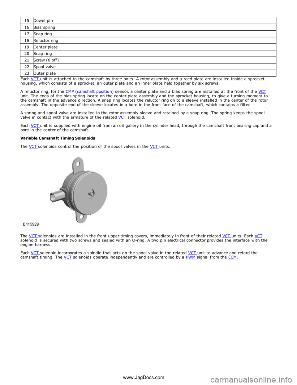
16 Bias spring 17 Snap ring 18 Reluctor ring 19 Center plate 20 Snap ring 21 Screw (6 off) 22 Spool valve 23 Outer plate Each VCT unit is attached to the camshaft by three bolts. A rotor assembly and a reed plate are installed inside a sprocket housing, which consists of a sprocket, an outer plate and an inner plate held together by six screws.
A reluctor ring, for the CMP (camshaft position) sensor, a center plate and a bias spring are installed at the front of the VCT unit. The ends of the bias spring locate on the center plate assembly and the sprocket housing, to give a turning moment to
the camshaft in the advance direction. A snap ring locates the reluctor ring on to a sleeve installed in the center of the rotor
assembly. The opposite end of the sleeve locates in a bore in the front face of the camshaft, which contains a filter.
A spring and spool valve are installed in the rotor assembly sleeve and retained by a snap ring. The spring keeps the spool
valve in contact with the armature of the related VCT solenoid.
Each VCT unit is supplied with engine oil from an oil gallery in the cylinder head, through the camshaft front bearing cap and a bore in the center of the camshaft.
Variable Camshaft Timing Solenoids
The VCT solenoids control the position of the spool valves in the VCT units.
The VCT solenoids are installed in the front upper timing covers, immediately in front of their related VCT units. Each VCT solenoid is secured with two screws and sealed with an O-ring. A two pin electrical connector provides the interface with the
engine harness.
Each VCT solenoid incorporates a spindle that acts on the spool valve in the related VCT unit to advance and retard the camshaft timing. The VCT solenoids operate independently and are controlled by a PWM signal from the ECM. www.JagDocs.com
Page 868 of 3039

cooling jets and the timing chain lubrication jets.
The oil returns to the oil pan under gravity. Large drain holes through the cylinder heads and cylinder block ensure the rapid
return of the oil to the sump pan. System replenishment is through the oil filler cap on the LH cylinder head cover.
An oil evacuation tube is installed to allow oil to be drawn from the sump pan. The upper end of the oil evacuation tube is
located under the oil filler cap.
An oil drain plug is installed in the RH side of the sump pan.
Oil Pump Nominal Operating Pressures
Engine Speed, rev/min Temperature, °C (°F) Pressure, bar (lbf/in2
) Idle 20 (68) 2.0 (29.0) 1500 20 (68) 6.0 (87.0) 3000 40 (104) 6.2 (90.0) 3000 110 (230) 5.0 (72.5) 3000 130 (266) 4.0 (58.0) Oil Level Monitoring
Oil level monitoring is provided by an oil level and temperature sensor that measures the oil level in the sump pan. The oil
level can be displayed in the message center of the instrument cluster.
The oil level and temperature sensor supplies the ECM with a signal containing the level and temperature of the oil in the sump pan. The oil level and temperature sensor is secured to the bottom of the sump pan with three screws and sealed with a
gasket.
The oil level and temperature sensor sends an ultrasonic pulse vertically upward and measures the time taken for the pulse to
be reflected back from the top surface of the oil. This time is compared with the time taken for an ultrasonic pulse to travel a
reference distance within the oil level and temperature sensor to determine the oil level. The oil level reading is combined with
the oil temperature reading and transmitted in a PWM signal to the ECM.
Oil Level and Temperature Sensor Specifications
Feature Details Power source Battery Voltage Level Accuracy ±2 mm (±0.08 in.) at temperatures of -30 °C (-22 °F)) and above; (±4 mm (±0.16 in.) at
temperatures below -30 °C (-22 °F)) Temperature Accuracy ±2 °C (±3.6 °F) Operating Level Range 116 to 147 mm (4.57 to 5.79 in.)
Page 1125 of 3039

- Megafuse fixing nuts
Engine junction box
- Megafuse
- Megafuse fixing nuts
- Fuses
- Engine control module relay Were any circuits or wiring short circuit to ground, short circuit to power, open circuit, high resistance or any
connectors damaged from water ingress, pin damage and/or corrosion?
Yes
Rectify as required
No
Proceed to the next step. A9 'Cooling fan validation procedure' A9: COOLING FAN VALIDATION PROCEDURE 1 Ensure the hood is closed 2 Allow vehicle to idle 3 Switch ON air conditioning and set to lowest temperature and highest fan speed 4 Allow vehicle to reach operating temperature (approximately 90 degrees C). Using the manufacturer approved diagnostic system monitor datalogger signals – Engine Coolant Temperature (0XF405) -and -
Electric Fan PWM Control - Commanded (0X03F9) - as the engine coolant temperature reaches
operating temperature the fan speed should also increase between the values of 9 and 90% Did the cooling fan rotate at increasing speed as engine coolant temperature increased?
Yes
Return vehicle to customer
No
Contact dealer technical support DTC Index
For a list of diagnostic trouble codes (DTCs) that could be logged on this vehicle, please refer to Section 100-00.
REFER to: Electronic Engine Controls (303-14D Electronic Engine Controls - V8 S/C 5.0L Petrol, Diagnosis and Testing). www.JagDocs.com
Page 1363 of 3039
Defaults to base mapping for the ignition timing, with no cylinder correction
Disables the VCT system.
ENGINE COOLANT TEMPERATURE SENSORS
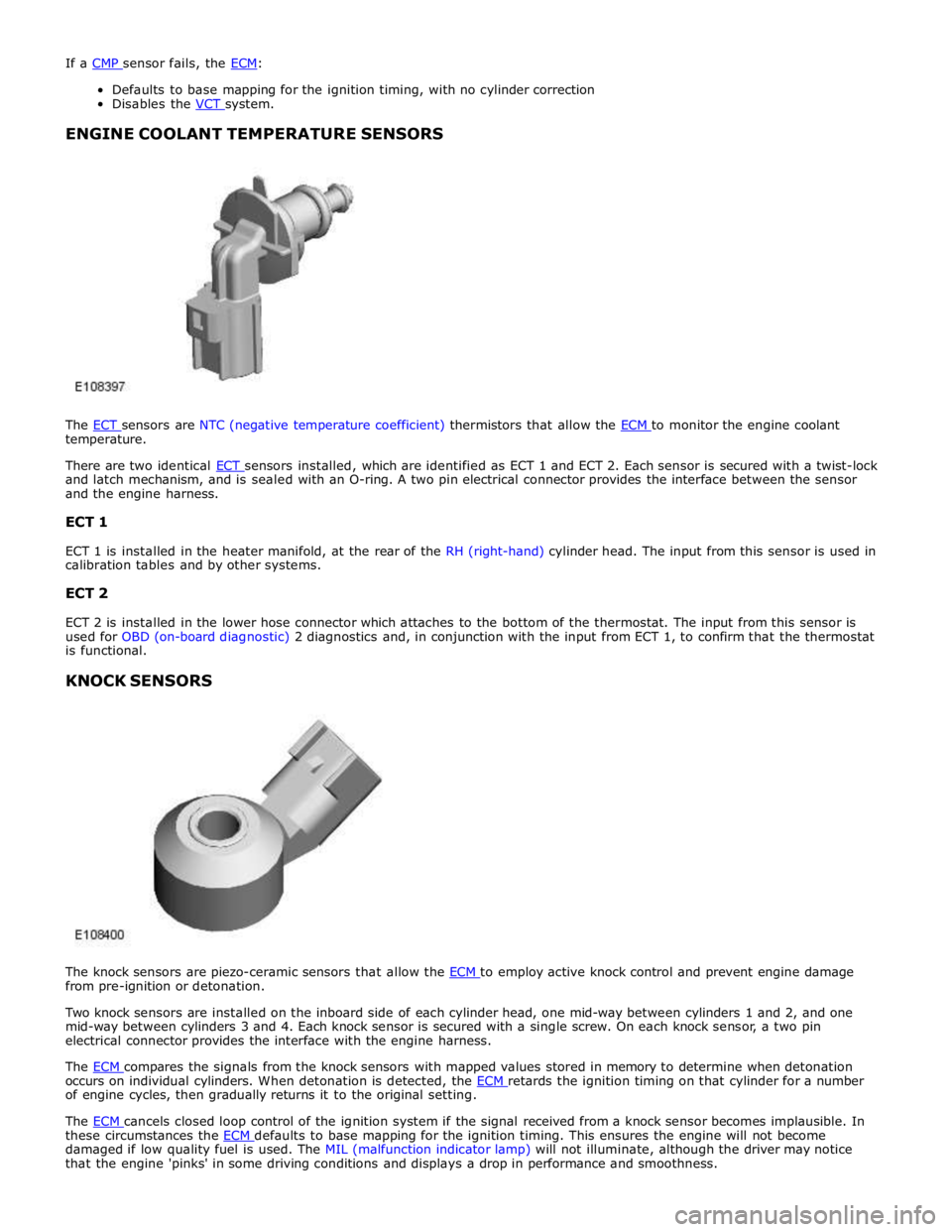
The ECT sensors are NTC (negative temperature coefficient) thermistors that allow the ECM to monitor the engine coolant temperature.
There are two identical ECT sensors installed, which are identified as ECT 1 and ECT 2. Each sensor is secured with a twist-lock and latch mechanism, and is sealed with an O-ring. A two pin electrical connector provides the interface between the sensor
and the engine harness.
ECT 1
ECT 1 is installed in the heater manifold, at the rear of the RH (right-hand) cylinder head. The input from this sensor is used in
calibration tables and by other systems.
ECT 2
ECT 2 is installed in the lower hose connector which attaches to the bottom of the thermostat. The input from this sensor is
used for OBD (on-board diagnostic) 2 diagnostics and, in conjunction with the input from ECT 1, to confirm that the thermostat
is functional.
KNOCK SENSORS
The knock sensors are piezo-ceramic sensors that allow the ECM to employ active knock control and prevent engine damage from pre-ignition or detonation.
Two knock sensors are installed on the inboard side of each cylinder head, one mid-way between cylinders 1 and 2, and one
mid-way between cylinders 3 and 4. Each knock sensor is secured with a single screw. On each knock sensor, a two pin
electrical connector provides the interface with the engine harness.
The ECM compares the signals from the knock sensors with mapped values stored in memory to determine when detonation occurs on individual cylinders. When detonation is detected, the ECM retards the ignition timing on that cylinder for a number of engine cycles, then gradually returns it to the original setting.
The ECM cancels closed loop control of the ignition system if the signal received from a knock sensor becomes implausible. In these circumstances the ECM defaults to base mapping for the ignition timing. This ensures the engine will not become damaged if low quality fuel is used. The MIL (malfunction indicator lamp) will not illuminate, although the driver may notice
that the engine 'pinks' in some driving conditions and displays a drop in performance and smoothness.
Page 1366 of 3039
the period of rich to lean and lean to rich switching monitors the response rate of the upstream sensors.
Diagnosis of electrical faults is continually monitored in both the upstream and downstream sensors. This is achieved by
checking the signal against maximum and minimum threshold, for open and short circuit conditions.
If a heated oxygen sensor fails:
The ECM defaults to open loop fueling for the related cylinder bank The CO (carbon monoxide) and emissions content of the exhaust gases increases
The exhaust smells of rotten eggs (hydrogen sulphide).
With a failed heated oxygen sensor, the engine will suffer from unstable operation and reduced performance.
ACCELERATOR PEDAL POSITION SENSOR
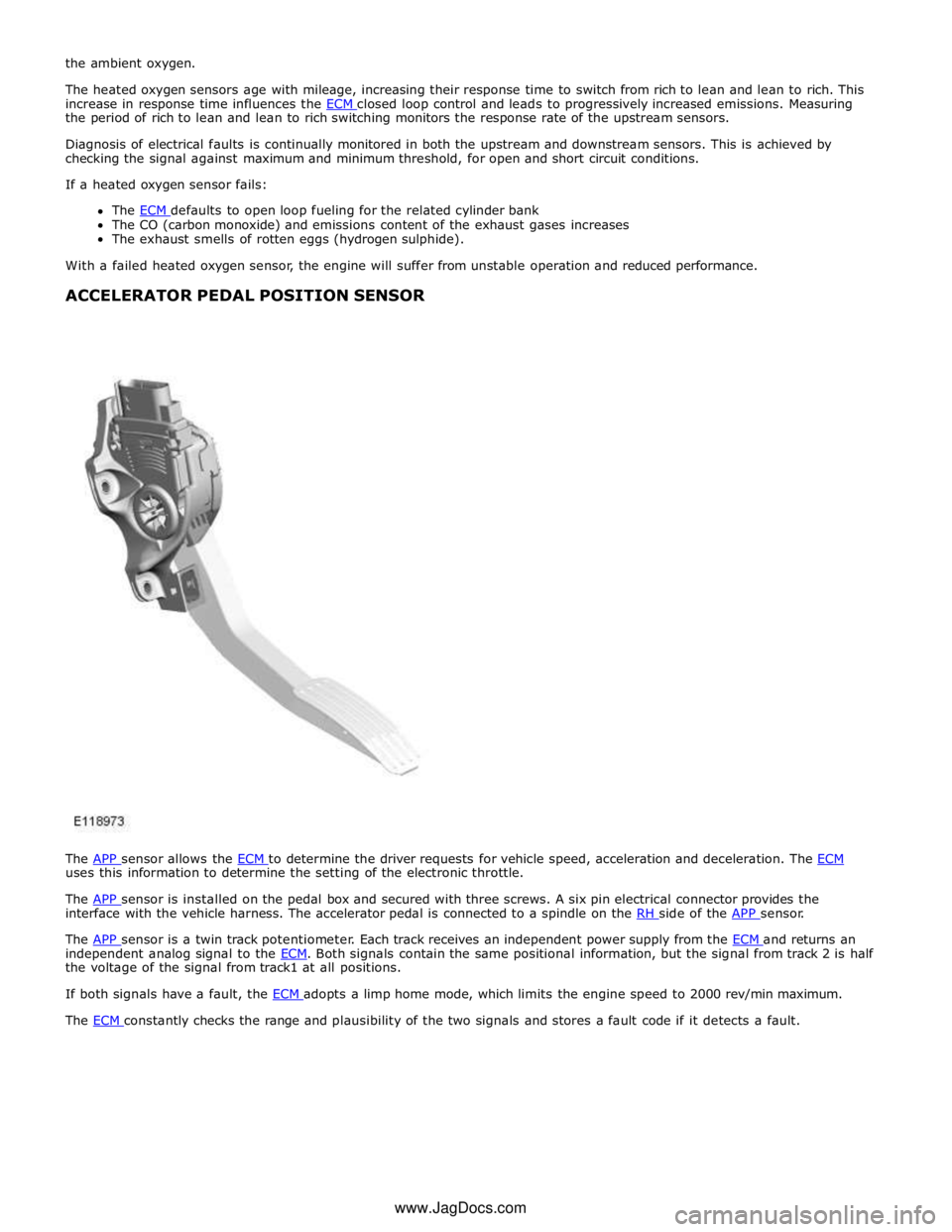
The APP sensor allows the ECM to determine the driver requests for vehicle speed, acceleration and deceleration. The ECM uses this information to determine the setting of the electronic throttle.
The APP sensor is installed on the pedal box and secured with three screws. A six pin electrical connector provides the interface with the vehicle harness. The accelerator pedal is connected to a spindle on the RH side of the APP sensor.
The APP sensor is a twin track potentiometer. Each track receives an independent power supply from the ECM and returns an independent analog signal to the ECM. Both signals contain the same positional information, but the signal from track 2 is half the voltage of the signal from track1 at all positions.
If both signals have a fault, the ECM adopts a limp home mode, which limits the engine speed to 2000 rev/min maximum. The ECM constantly checks the range and plausibility of the two signals and stores a fault code if it detects a fault. www.JagDocs.com